Oct 28, 2002 - The protocol is tailored to the .... To cope with this increasing software complexity, and to facilitate ... Advantages and disadvantages are presented. ..... The Event Channel Factory is the first object to be created when setting up ...
Design and Implementation of a Realtime CORBA Event Service with Support for a Realtime Network Entwurf und Implementierung eines echtzeitf¨ahigen CORBA Event Service mit Unterst¨utzung eines echtzeitf¨ahigen Netzwerkes Rainer Finocchiaro Matrikelnummer: 206146
Diplomarbeit an der Rheinisch-Westf¨alischen Technischen Hochschule Aachen Fakult¨at f¨ur Elektrotechnik und Informationstechnik Lehrstuhl f¨ur Betriebssysteme
Betreuer:
Univ.-Prof. Dr. habil. Thomas Bemmerl Dipl.-Ing. Andreas Jabs
.
Ich versichere hiermit, dass ich die vorliegende Arbeit selbst¨andig und ohne Benutzung anderer als der angegebenen Hilfsmittel angefertigt habe. Alle Stellen, die w¨ortlich oder sinngem¨aß aus ver¨offentlichten und nicht ver¨offentlichten Schriften entnommen sind, sind als solche kenntlich gemacht. Die Arbeit ist in gleicher oder a¨ hnlicher Form noch nicht als Pr¨ufungsarbeit eingereicht worden.
Aachen, October 28, 2002
.
Abstract This thesis focuses on the design of an Event Service complying to the OMG Event Service standard. The design and the implementation developed within the scope of this thesis provide realtime characteristics. Providing event-driven transfer of messages, support for realtime traffic and broadcasting as native addressing mode, the CAN bus is used as the underlying network of choice. A new protocol for the efficient distribution of Events in a CAN-based distributed control system is developed. The protocol is tailored to the CAN bus and needs very low overhead by utilising the CAN-specific features. In order to examine its realtime characteristics, latency measurements have been made.
Diese Diplomarbeit konzentriert sich auf den Entwurf eines zum OMG Event Service Standard kompatiblen Ereignisdienstes (Event Service). Insbesondere wurde beim Entwurf und der Implementierung, die im Rahmen dieser Diplomarbeit entwickelt wurde, auf Aspekte der Echtzeitf¨ahigkeit Wert gelegt. Der CAN Bus als ereignisbasiertes, echtzeitf¨ahiges Netzwerk, das Broadcasting als native Addressierung benutzt, dient als Grundlage, auf der ein Protokoll zur effizienten Verteilung von Events entwickelt wurde. Das Protokoll ist auf den CAN Bus zugeschnitten und erzeugt nur einen sehr geringen Overhead. Um die Echtzeiteigenschaften des Protokolls zu untersuchen, wurden LatenzzeitMessungen durchgef¨uhrt, deren Ergebnisse abschließend diskutiert werden.
vi
Contents
1. Introduction 2. Technical Background 2.1. Distributed Object Systems . . . . . . . . 2.1.1. Object Management Architecture 2.1.2. CORBA . . . . . . . . . . . . . . 2.1.3. RMI . . . . . . . . . . . . . . . . 2.1.4. DCOM . . . . . . . . . . . . . . 2.2. Event Service . . . . . . . . . . . . . . . 2.2.1. Event Channel Factory . . . . . . 2.2.2. Event Channel . . . . . . . . . . 2.2.3. Administration Objects . . . . . . 2.2.4. Proxies . . . . . . . . . . . . . . 2.2.5. Event Data . . . . . . . . . . . . 2.2.6. Example Scenario . . . . . . . . 2.3. Notification Service . . . . . . . . . . . . 2.3.1. Form of Event Data . . . . . . . . 2.3.2. Filtering of Events . . . . . . . . 2.3.3. Quality of Service . . . . . . . . 2.3.4. Event Domain Service . . . . . . 2.4. Realtime Systems . . . . . . . . . . . . . 2.5. Realtime CORBA . . . . . . . . . . . . . 2.6. CAN Bus . . . . . . . . . . . . . . . . .
1
. . . . . . . . . . . . . . . . . . . .
. . . . . . . . . . . . . . . . . . . .
. . . . . . . . . . . . . . . . . . . .
. . . . . . . . . . . . . . . . . . . .
. . . . . . . . . . . . . . . . . . . .
. . . . . . . . . . . . . . . . . . . .
. . . . . . . . . . . . . . . . . . . .
. . . . . . . . . . . . . . . . . . . .
. . . . . . . . . . . . . . . . . . . .
. . . . . . . . . . . . . . . . . . . .
. . . . . . . . . . . . . . . . . . . .
. . . . . . . . . . . . . . . . . . . .
. . . . . . . . . . . . . . . . . . . .
. . . . . . . . . . . . . . . . . . . .
. . . . . . . . . . . . . . . . . . . .
. . . . . . . . . . . . . . . . . . . .
. . . . . . . . . . . . . . . . . . . .
3 3 4 5 7 8 8 10 10 10 10 10 11 13 14 14 14 14 15 16 18
3. Related Work 21 3.1. MICO Event Service . . . . . . . . . . . . . . . . . . . . . . . . . . . . 21 3.2. TAO Event Service . . . . . . . . . . . . . . . . . . . . . . . . . . . . . 22 3.3. Publisher/Subscriber Model for the CAN Bus . . . . . . . . . . . . . . . 23 4. Architecture, Design and Implementation 4.1. Development Platform . . . . . . . . . . . . 4.2. Test Environment . . . . . . . . . . . . . . . 4.3. Setup Scenarios . . . . . . . . . . . . . . . . 4.3.1. Centralised Event Service for Ethernet
. . . .
. . . .
. . . .
. . . .
. . . .
. . . .
. . . .
. . . .
. . . .
. . . .
. . . .
. . . .
. . . .
. . . .
. . . .
27 27 27 28 28
viii
Contents
4.4.
4.5.
4.6.
4.7.
4.8.
4.3.2. Distributed Event Service with Handler for CAN Bus . . . . . . CAN Event Broadcast Protocol and CAN Bus Handler Implementation 4.4.1. CAN Bus Handler . . . . . . . . . . . . . . . . . . . . . . . . 4.4.2. Protocol Information in CAN Message Identifier . . . . . . . . 4.4.3. Endianness Issues . . . . . . . . . . . . . . . . . . . . . . . . . 4.4.4. Fragmentation and Reassembly . . . . . . . . . . . . . . . . . 4.4.5. Protocol Information in CAN Message Body . . . . . . . . . . 4.4.6. Detection of Corrupted Data . . . . . . . . . . . . . . . . . . . Event Service Design Details . . . . . . . . . . . . . . . . . . . . . . . 4.5.1. Prioritisation of Events . . . . . . . . . . . . . . . . . . . . . . 4.5.2. Priority Queueing and Threaded Dispatching of Events . . . . . 4.5.3. Polling or Thread Blocking in ProxyPullSuppliers . . . . . . . 4.5.4. Polling or Thread Blocking in ProxyPullConsumers . . . . . . 4.5.5. Usage of ESD Library and Driver for the CAN Bus . . . . . . . API . . . . . . . . . . . . . . . . . . . . . . . . . . . . . . . . . . . . 4.6.1. Standard API . . . . . . . . . . . . . . . . . . . . . . . . . . . 4.6.2. Extensions to the standard Event Service API . . . . . . . . . . Implementation of Basic Functionality . . . . . . . . . . . . . . . . . . 4.7.1. Priority Queue . . . . . . . . . . . . . . . . . . . . . . . . . . 4.7.2. Readers/Writer Locks . . . . . . . . . . . . . . . . . . . . . . Problems and Solutions . . . . . . . . . . . . . . . . . . . . . . . . . .
. . . . . . . . . . . . . . . . . . . . .
30 34 35 37 39 40 41 42 43 44 45 45 46 48 49 49 49 52 52 53 54
5. Benchmarks – Latency Measurement 55 5.1. Priority Queueing disabled . . . . . . . . . . . . . . . . . . . . . . . . . 56 5.2. Priority Queueing enabled . . . . . . . . . . . . . . . . . . . . . . . . . 58 6. Conclusions and Outlook
63
A. Appendix – Source Code of Benchmarks 65 A.1. Source of the Channelserver . . . . . . . . . . . . . . . . . . . . . . . . 65 A.2. Source of the Asynchronous Ping Example . . . . . . . . . . . . . . . . 67 A.3. Source of the Asynchronous Pong Example . . . . . . . . . . . . . . . . 71 Glossary
75
List of Figures
77
Bibliography
79
1. Introduction
Control systems in automotive, manufacturing and aerospace industries have to fulfill tasks of increasing complexity. All these systems provide growing safety and comfort functionality. Today, more and more automobiles for example are equipped with safety systems like ABS (Anti Blocking System), ESD (Electronic Skid Detection), automatic gearboxes, systems ensuring the correct distance to the surrounding traffic, and comfort utilities like multimedia systems and air conditioning. To implement these systems in a cost-effective way, small specialised and inexpensive functional units, such as sensors, actuators and processing units, are combined into a distributed system. This distributed approach is furthermore preferred over a setup of a single highly powerful general purpose computing unit, as it facilitates implementation of fault tolerance. Unfortunately, this distribution of functional units comes at a cost: development of software for distributed systems is inherently more complex than it is for centralised systems. To cope with this increasing software complexity, and to facilitate programming of distributed systems in general, middleware has been developed. General purpose middleware like CORBA, Java/RMI and DCOM has some drawbacks when used in Distributed Realtime Embedded (DRE) systems [1]: it usually has a high memory footprint (some ORB implementations require several megabytes of memory) and offers poor realtime functionality. To address these problems, specialised middleware for DRE systems has been developed at the Chair of Operating Systems [2]. Communication in distributed systems that most importantly exchange sensor data is rarely limited to two communication partners. Often, a varying number of functional units is interested in sensor data from a varying number of sensors. The CORBA ORB alone only provides point-to-point communication, which badly represents the needs of the above mentioned DRE systems. A more decoupled communication scheme, where producers and consumers of data do not have to know about each other, is provided by the CORBA Event Service [3]. In this diploma thesis, an implementation of the CORBA Event Service specification is developed, which is optimised for the use over the CAN bus (Controller Area Network
2
1 Introduction
[4]). The CAN bus is a widely-used realtime control network, that features broadcasting as its native addressing scheme. This implementation of the Event Service makes extensive use of the CAN bus features in order to provide realtime characteristics and allow resource conscious delivering of event data from producers to consumers. The thesis is organised as follows: Chapter 2 briefly introduces the technical background and terminology. Chapter 3 presents related works and current research projects. Chapter 4 gives an insight into the software developed within the scope of this thesis. Preliminary benchmarks are discussed in chapter 5. Chapter 6 concludes the status of the developed implementation of the Event Service and gives an outlook into future expansions. Basic knowledge of Object Oriented Programming (OOP) is assumed and is very helpful for understanding this thesis.
2. Technical Background
In this chapter, technical terms are explained, which are necessary to understand the Event Service. A brief overview of the underlying Common Object Request Broker Architecture (CORBA) and competing systems is given in the first section. The second section describes the architecture of the CORBA Event Service and the third section shortly introduces the Notification Service as an enhanced Event Service. In the following sections, a brief insight into realtime issues and the underlying CAN bus is given.
2.1. Distributed Object Systems Over the last years and continuing in the future, hardware is getting faster. This allows more and more complex software to run on the hardware. This in turn allows problems of increasing complexity to be solved. In order to manage the growing complexity of software projects, several efforts have been made to modularise them. One technique to simplify programming of complex problems is Object Oriented Programming (OOP) , which is an attempt to make software more similar to the environment we are accustomed to. Like in real life, OOP deals with objects that have properties (e.g. colour, size, age, etc.) and functionality (e.g. coffee machines make coffee, monitors display pictures, children grow and ask annoying questions, etc.). Examples of programming languages that support Object Orientation are: Smalltalk, C++, Java, etc. These languages offer the use of Objects, which are usually represented simply as data structures in the main memory of a computer. Distributed Object Systems (DOS) are an extension of the idea of using software Objects onto distributed systems. Distributed systems are those, where parts and components of an application can be on different computers, which are connected by a network. DOS therefore provide means for accessing and handling Objects distributed on connected computers. The next subsections present the major Distributed Object Systems in short form.
4
2 Technical Background
Advantages and disadvantages are presented. Special emphasis is layed on OMA and CORBA, as the Event Service developed in the scope of this thesis is based on these technologies.
2.1.1.
Object Management Architecture
In this subsection, the Object Management Architecture (OMA) is introduced. The OMA is a standard developed by the Object Management Group (OMG). CORBA and the Event Service are part of the OMA. Applications share a lot of functionality. The OMA is a set of standards defining a middleware, which aims to provide this functionality: notification of objects, creation and desctruction of objects, passing object references around, securing operations and making them transactional, etc. Applications belonging to the same business domain (e.g. Telecommunication) share even more functionality.
Application Objects
Vertical CORBA Facilities
Horizontal CORBA Facilities
Object Request Broker
CORBA Services
Figure 2.1.: Object Management Group’s Open Management Architecture As depicted in figure 2.1, the OMA defines Objects on top of CORBA (refer to the next section for further information on CORBA). These objects are divided into four categories: (1) CORBAservices, (2) CORBAfacilities, (3) CORBAdomain objects, and (4) Application Objects.
1. The CORBAservices provide basic functionality, such as Naming Service, Object Trading Service, Persistant State Service, Notification Service, and – most important for this thesis – the Event Service. All these services are closely tied to the ORB infrastucture.
2.1 Distributed Object Systems
5
2. The Horizontal CORBAfacilities are placed between the basic CORBAservices and the high level Application Objects (described below). In contrast to the Vertical Domain CORBAfacilities (described next), these facilities provide functionality that is useful across domains. 3. The Vertical Domain CORBAfacilities are the area where most of the current development takes place. The OMG together with representatives from each industry define standard interfaces for standard objects that every company in a particular industry can share. 4. The Application Objects are objects built on top of the above mentioned services and facilities. They are typically customised to a specific need and are therefore not standardised by the OMG. The services mentioned above are specified in the form of interfaces. These interfaces are defined in the Interface Definition Language IDL (which is an OMG standard by itself, belonging to the OMA as well). The OMG only defines the standards of the OMA. Software vendors implement these standards and sell the implementations. In addition to commercial implementations, some are available as open source developments.
2.1.2.
CORBA
This section describes the technology that the Event Service (together with all other CORBA services and facilities) is based on. CORBA is one of the standards of the OMA, defined by the OMG. CORBA is the acronym for Common Object Request Broker Architecture, OMG’s open architecture and infrastructure that computer applications use to work together over networks. Using the standard protocol IIOP, a CORBA-based program from any vendor, on almost any computer, operating system, programming language, and network, can interoperate with a CORBA-based program from the same or another vendor, on almost any other computer, operating system, programming language, and network. CORBA applications are composed of Objects. The interfaces – describing the functionality of each object – are defined in IDL, OMG’s Interface Definition Language. These definitions are programming language independent; IDL is currently mapped via OMG standards to the following languages: C, C++, Java, COBOL, Smalltalk, ADA, Lisp, Python and IDLscript. The strict separation of interface and implementation is the essence of CORBA. The interface is promoted throughout the system, the implementation, on the other hand, is
6
2 Technical Background
hidden from the rest of the system. Clients access objects only through their advertised interface. operation() Client
IDL Stub
Servant (Object Implementation) IDL Skeleton
Request Object Request Broker (ORB)
Figure 2.2.: A Request passing from Client to Servant Figure 2.2 gives an overview about CORBA, the Object Request Broker (ORB) as its main component, the IDL, and the other components involved in a basic CORBA system: • The interface definition of a CORBA Object (written in IDL) is compiled into client stub and object skeleton (in the target programming language) – this is done by the IDL-compiler, which is delivered with the CORBA implementation. • The implementation of the Object (called the servant) is programmed using the object skeleton and the client may use all functionality found in the client stub. • Stub and skeleton serve as proxies for clients and servants, respectively. Due to this proxy functionality, client (shown on the left) and servant (shown on the right) can communicate without problems, even when they are written in different programming languages and if they are run on different ORBs from different vendors. In CORBA every object instance has its own Object Reference (comparable to a pointer in C/C++, but valid across computer boundaries). Clients use the Object Reference to direct their invocations to the exact instance they want to invoke. The client acts, as if it was invoking operations directly on the servant. Instead, it invokes the operation on the IDL stub, which acts as a proxy. The invocation passes through the stub, continues through the ORB and the skeleton on the implementation side, to get to the object instance, where it is executed. Summarising, the process of program creation is based on the following steps: 1. Create the interface definition of an object in the abstract interface definition language IDL.
2.1 Distributed Object Systems
7
2. Compile the interface definition into a servant skeleton with the IDL compiler. The skeleton is compiled into the programming language used for the later implementation of the servant (i.e. the servant should be programmed in C++, then generate the skeleton in C++). 3. Implement the servant in the programming language of choice. 4. Compile the interface definition into a client stub with the IDL compiler. The stub is compiled into the desired programming language for the implementation of the client. This decision is independent of the language, the servant is implemented in. 5. Implement the client, or even many clients in many different languages. For a good further introduction to CORBA, see [5]. Even more and more detailed information can be found on the OMG home page on the WWW at http://www.omg.org and in the CORBA specification [6]. Information specific to the implementation of CORBA, which is used for this Event Service, can be found in [2].
2.1.3.
RMI
This section will give a short introduction to Remote Method Invocation (RMI). It will compare properties and features of RMI with CORBA, the technology that the Event Service developed in this thesis is based on. RMI is a technology developed by SUN Microsystems. It is based on Java and extends the Java object handling principle to allow access to – and manipulation of – remote Java objects in a very similar manner to local objects. This tight coupling of RMI with Java has the advantage that programmers, who are familiar with Java, do not have to learn a new programming language or technology. Learning to use the distributed extensions of Java is very easy and not very time consuming, according to David Curtis [7]. Java has the advantage of being (mostly) platform independent, allowing the same program (in Java Bytecode) to be run on different platforms and under different operating systems. Being a Java only technology, RMI allows to migrate not only interfaces but also implementations from one computer to another. This is by design not possible with CORBA. Imagine a C++ object located on an intel compatible computer with Linux as the operating system, sent over the wire to a Power PC platform, running MacOS and continuing to work there. These advantages of being a Java-only technology have their drawbacks, as well. Integrating and extending existing programs in other languages is not easily possible and most importantly Java is just one of many languages having its strengths (portability, ease
8
2 Technical Background
of use, and plethora of existing classes for many tasks) and its weaknesses (slow, due to the high abstraction from the hardware; during automatical garbage collection of unused memory, the rest of the system is blocked, making it problematic for time-critical systems). Having explained a few difference concerning Java/RMI and CORBA, Curtis sees these two technologies more as supplementary than as competitors. He describes Java/RMI as a programming technology and CORBA as an integration technology. Systems programmed with the former technology, as open as they might seem, are closed to Java and its properties (positive and negative). For more information on RMI, see [8]. An in-depth comparison of CORBA, RMI and DCOM, although from 1998, can be found at [9].
2.1.4.
DCOM
This section introduces Microsoft’s Distributed Common Object Model (DCOM). As [10] states, DCOM is the distributed extension to COM (Component Object Model) that builds an object remote procedure call (ORPC) layer on top of DCE RPC to support remote objects. A COM object can support multiple interfaces, each representing a different view or behaviour of the object. An interface consists of a set of functionally related methods. A COM client interacts with a COM object by acquiring a pointer to one of the object’s interfaces and invoking methods through that pointer, as if the object resides in the client’s address space. COM specifies that any interface must follow a standard memory layout, which is the same as the C++ virtual function table. Since the specification is at the binary level, it allows integration of binary components possibly written in different programming languages such as C++, Java and Visual Basic. More information can be found on the Microsoft home page [11]. An in-depth comparison of CORBA, RMI and DCOM, although from 1998, can be found at [9].
2.2. Event Service With the Event Service [3], the OMG satisfies the demand for a more decoupled communication between distributed objects. Standard CORBA requests result in the synchronous execution of an operation by an object. These requests are directed to a particular object (see section 2.1.2 on page 5). In contrast to that, the Event Service allows for a looser binding between senders and receivers of requests. Participants of the Event Service no longer have to know with how many other objects they communicate, nor where those other objects are located; even more than that: they do not even have to know if these
2.2 Event Service
9
other objects exist at all. They just send their event data to or get it from the Event Channel – and do not have to care about the rest. The Event Service defines two roles for objects: the supplier role and the consumer role. Suppliers produce event data and consumers process event data. These two roles are both subdivided into an active and a passive model.
• Suppliers (shown on the left-hand side in figure 2.3) can either actively push their produced event data to the Event Service – this is called the Push-Model, or passively wait until the Event Service pulls it from them (Pull-Model). • Consumers (shown on the right-hand side in figure 2.3), on the other hand, can actively pull event data from the Event Service (Pull-Model), or passively wait until the Event Service pushes it to them (Push-Model).
Event Service Push Supplier
Proxy Push Consumer
Event Channel
Supplier Admin
Pull Supplier
Proxy Pull Consumer
Proxy Push Supplier
Push Consumer
Proxy Pull Supplier
Pull Consumer
Consumer Admin
Event Channel Factory Event Flow
Not part of the OMG Standard
push()
pull()
create()
Figure 2.3.: General Structure of the Event Service In the next subsections the components of the Event Service – as shown inside the grey box in figure 2.3 – are described in greater detail in bottom-up order: Starting with the Event Channel Factory component, which is first created when setting up an Event Service, and continuing towards the Proxies, which are created when connecting to a specific Event Channel. In section 2.2.6 on page 11, a real-world example demonstrates how all these components interact.
10
2.2.1.
2 Technical Background
Event Channel Factory
The Event Channel Factory is the first object to be created when setting up an Event Service. Its purpose is to offer an interface for the creation of Event Channels. With an Event Channel Factory running it is possible for local and remote objects to create any number of Event Channels. Platform-specific details of Event Channel creation are hidden from the user of the Event Channel Factory.
2.2.2.
Event Channel
The Event Channel is created by the Event Channel Factory. It is the main component of the Event Service. Responsible for creation of Administration objects, it keeps track of connected objects and multiplexes event data. All event data sent from suppliers to consumers passes through the Event Channel.
2.2.3.
Administration Objects
There are two Administration objects: one is used by event consuming objects (ConsumerAdmin) and one by event producing objects (SupplierAdmin). These Admins are responsible for creating Proxy objects for the Pull-Model and the Push-Model (i.e. the SupplierAdmin creates ProxyPushConsumers and ProxyPullConsumers, whereas the ConsumerAdmin creates ProxyPushSuppliers and ProxyPullSuppliers). The Administration object’s only purpose is Proxy-creation, i.e. event data passing from suppliers through the Event Channel to consumers does not pass through the Admins.
2.2.4.
Proxies
Proxies are the last objects created when connecting to the Event Channel. They are created by the Administration objects. Each supplier and each consumer connects to exactly one Proxy object. The Proxy objects offer a consumer interface to the supplier and a supplier interface to the consumer so that each object connecting to the Event Service has the impression of being connected to and communicating with only one partner.
2.2.5.
Event Data
The event data, which is sent by suppliers via the Event Channel to the consumers, has to be in the form of a CORBA::Any (see figure 2.4 on the next page). This is a standard
2.2 Event Service
11
data type, which basically consists of the data itself (a series of bytes) and a Type Code containing information about how to interpret this data (e.g. as integer, string, character or any other of the 32 CORBA defined data types). The Event Service standard also mentions Typed Events; they are not present in most available Event Service implementations, though.
Type Code
Data Buffer
Figure 2.4.: Structure of the CORBA::Any
2.2.6.
Example Scenario
In this section, the following real-world example is used to explain the purpose of the Event Channel and the interactions between its components: Central Computer
ent
Ev Event
EC
Event
Ev
ent
Temperature Display 77°C
... Oil Temperature Sensor
Figure 2.5.: Oil Temperature Sensor pushing Event Data to Consumers As depicted in figure 2.5, there is a sensor ready to send the oil temperature of a car engine to whoever is interested, at a regular interval. Interested components could be the central computer, a display on the dash board, etc. As the sensor does not know exactly who the interested components are, how many there are, or where they are located, it makes use of the Event Service. The sensor wants to send its data (i.e. the oil temperature) at a regular interval, which means that it has to
12
2 Technical Background
actively push the data. It is therefore called a Push Supplier in contrast to a Pull Supplier, which passively waits until some interested component pulls the data from it (compare with figure 2.3 on page 9 and section 2.2.4 on page 10). When the car is started, there is no Event Channel dedicated to the oil temperature. Only the Event Service, which provides an Event Channel Factory interface, is started. The Central Computer uses the Event Channel Factory to create the needed oiltemperature Event Channel (this could in fact be done by e.g. the sensor, as well). After the specific Event Channel is set up, any consumer (here the Central Computer, the display, etc.) or supplier (here the sensor) can connect to it. Connecting is a three-step process which involves the other components, which are not mentioned by now in this example (the Administration objects and the Proxies). This process is described for a sensor representing a Push Supplier (as mentioned above). A close look onto figure 2.3 on page 9 is helpful to visualise the components referred to in the following listing. 1. First of all, the Event Channel is called to return a Supplier Admin. The Supplier Admin is responsible for creating Pull- or PushConsumerProxies. 2. Then the sensor calls the Supplier Admin to create and return a ProxyPushConsumer. 3. As a last step, the sensor (or Push Supplier) connects to the ProxyPushConsumer. The connection from the supplier to the Event Channel is established. The Central Computer and display have to perform analogous actions on the consumer side (obtaining the Admin and Proxy and connecting). As soon as a consumer (e.g. the display) and a supplier (e.g. the sensor) are connected to the Event Channel, the first real sending of data (e.g. the oil temperature) from suppliers to consumers can happen. The complete way of the Event is as follows (see figure 2.6 on the facing page): 1. The sensor pushes the Event to its associated ProxyPushConsumer. 2. The ProxyPushConsumer sends it to the Event Channel (bypassing the Supplier Admin). 3. The Event Channel transfers the Event to each registered ProxyPushSupplier (or ProxyPullSupplier in case there are Pull Consumers connected). 4. From there, the Event is finally pushed to the Push Consumers (or pulled by Pull Consumers). The Consumer Admin on the consumer side is bypassed, as well.
2.3 Notification Service
13
Event Service 77°C
ProxyPush Consumer
ProxyPush Supplier
77°C
ProxyPush Supplier
77°C
Central Computer
EC Temperature Display 77°C
Oil Temperature Sensor
Figure 2.6.: Flow of Temperature Data from Sensor to Consumers
2.3. Notification Service The Notification Service has been developed by the Object Management Group (OMG) as an enhancement of the Event Service described in section 2.2 on page 8. Improvements and extensions include Structured Events, Sequences of Events, Filtering of Events, Quality of Service and an Event Domain Service. A brief overview is given in the next subsections; for details please consult the Notification Service Specification [12].
Notification Service Push Supplier
Proxy Push Consumer
Structured Push Supplier
Structured Proxy Push Consumer
Filter
Filter
Supplier Admin
Consumer Admin
Push Consumer
Event Channel
Filter Supplier Admin
Sequence Pull Supplier
Proxy Push Supplier
Sequence Proxy Pull Consumer
Consumer Admin
Filter Structured Proxy Pull Supplier
Structured Pull Consumer
Sequence Proxy Pull Supplier
Sequence Pull Consumer
Event Flow
Figure 2.7.: General Structure of the Notification Service
14
2.3.1.
2 Technical Background
Form of Event Data
While the Event Service only allows to send event data in the form of a CORBA::Any (not worth mentioning the difficult-to-use and hard-to-implement Typed Events), the Notification service offers support for Structured Events (as successor for the Typed Events) and Sequences of Events, which allow for a series of events to be delivered in one operation.
2.3.2.
Filtering of Events
With the Event Service, every event data sent to a specific Event Channel is delivered to every consumer connected to this Event Channel. Unwanted Events have to be discarded in the event consuming application. In order to reduce the number of unwanted events being passed around, the Notification Service introduces filtering. Filters can be applied at each Proxy or Admin object (see figure 2.7 on the preceding page).
2.3.3.
Quality of Service
The Notification Service standardises support for Quality of Service attributes concerning reliability (of events and connections), queue management (including queuesize, delivering policy and discarding policy), event management (e.g. start-time, timeout, priority) and batch handling of events (batch size, pacing interval).
2.3.4.
Event Domain Service
Setting up a connection with the Event Service is a rather complicated process involving many steps (creating an Event Channel, obtaining an Administration object, obtaining a Proxy object and finally connecting). For each object, which should be connected, all these steps have to be programmed again and again. As a consequence, a lot of code is duplicated and exactly that is to be avoided as much as possible for several reasons: mistakes have to be corrected and the same changes have to be applied at several places in the code; the code size grows, etc. Another especially tedious and error prone action is to link several Event Channels together in order to form a federation of connected Event Channels. For each connection between two channels, the steps necessary to obtain a ProxySupplier and a ProxyConsumer, and connecting them, have to be performed. To alleviate these problem, the Notification Service introduces the Event Domain Service. This service simplifies the creation and federation of Notification Service Event
2.4 Realtime Systems
15
EC EC
Supplier
EC
EC
Consumer
EC EC Figure 2.8.: Federation of Event Channels
Channels by combining the large number of necessary steps into single, easy-to-use operations. It offers a higher level interface to the Notification Service.
2.4. Realtime Systems According to [13] and [14], Realtime Systems are computer systems, which must produce a result within a specified time. The overall correctness of the result is therefore dependent on the logical correctness of the result and on the time at which the result is produced. A logically correct result that comes too late, is a wrong result. Realtime Systems are always surrounded by an environment, whose dynamic determines the needed behaviour concerning time restrictions. The complete group of Realtime Systems is divided into hard and soft Realtime Systems. • Hard Realtime Systems are those, where violation of time constraints can lead to catastrophic consequences. A violation of time constraints is equally critical as a logically wrong result. An example is a cardiac pacemaker. Only when the signal to stimulate the heartbeat is generated at the correct time, the system works correctly. • Soft Realtime Systems are those, where the potential costs of an error are about the same as the costs of normal operation. An example is a system for sorting of letters. If a letter is put into a wrong box due to a violation of timing constraints, no severe damage is caused. In addition to timeliness, very important aspects of Realtime Systems are availability, reliability, fault tolerance and safety.
16
2 Technical Background • Availabilty is defined as the ratio between the time during which the system is operational and the elapsed time. Ensuring that a system is operational and functional at a given moment is usually provided through redundancy. • Reliability is defined as the probability that a given system survives the time interval [0,t] under the condition that it was operational at the time t = 0. • Fault tolerance is the ability of a computer system to operate according to the specification, in spite of a limited amount of faults occurring. • Safety is defined as freedom from those conditions that can cause death, injury, occupational illness, damage to or loss of equipment or property, or damage to the environment.
Realtime systems are comprised of hardware and software components. According to [13], microprocessors and networks are parts of the hardware, that to a high degree affect realtime characteristics of a complete system. Important software parts are the operating system and obviously the application software itself. It is important to note, that a realtime system can only provide predictability as a whole. Single components that fulfill realtime demands, can not ensure that the whole system works as expected. As stated in [14], realtime systems have undergone a lot of changes since the 60’s. Already at that time, process computers were used to control production machinery. With prices of computing hardware dropping dramatically and the computing power increasing at a very high rate, more and more, computer based automation systems are replacing the old mechanical and hydraulic systems. The same development happens in smaller and embedded systems: A middle class car is presented as an example of many control computers (e.g. for engine control, anti blocking system, air condition, airbag control, etc.) forming a distributed realtime embedded system. These systems are called DRE systems in [1]. Design and implementation of increasingly complex realtime systems is thought to be a major concern for computer scientists in the future. Middleware such as ROFES [2] and the realtime Event Service developed whithin the scope of this thesis are meant to support system developers in managing these DRE systems.
2.5. Realtime CORBA In this section, the Realtime CORBA standard [15], which is part of the CORBA Specification [6] is introduced. The Realtime CORBA standard defines some extensions to CORBA and together with the Minimum CORBA specification [16], it puts some restrictions on the use of CORBA
2.5 Realtime CORBA
17
parts, that conflict with realtime predictability. In [17] Schmidt and Kuhns give a good introduction into the key features of the realtime CORBA specification. Extensions are divided into (1) those for management of processor resources and (2) those for the management of inter-ORB communication. For the management of processor resources, RTCORBA specifies (1a) priority mechanisms, (1b) thread pools, (1c) standard synchronizers and (1d) a global scheduling service. Managing inter-ORB communication comprises (2a) selection and configuration of protocol properties and (2b) explicit binding. 1. Management of Processor Resources: • The RTCORBA specification defines native and CORBA priorities. Native priorities are those supported by the OS, CORBA priorities are used systemwide and mapped to native OS priorities. Priorities can be server-declared or client-propagated. In the first case, the server dictates at which priority an invocation is processed, in the latter, the client request’s priority is authoritative. The priority mechanisms are aimed at fixed-priority systems. • Threadpools allow for programming threaded CORBA applications using standard CORBA features. Before the RTCORBA specification, proprietary ORB extensions had to be used. Threadpools offer the possibility to specify properties such as maximum number of threads that are created initially, maximum number of threads that can be created dynamically, and the default priority. • Introducing standard thread programming features, synchronising has to be standardised as well. RTCORBA does this by defining a mutex variable. • The global scheduling service is introduced to simplify the mapping of higherlevel Quality of Service (QoS) parameters to lower-level OS mechanisms. Applications can specify their high-level scheduling requirements and the global scheduling service allocates system resources to meet these QoS needs. 2. Management of inter-ORB Communication: • Selection and configuration of protocol properties is enabled by the RTCORBA standard. The normal CORBA standard hides all details concerning object location and communication. While this ensures location transparency, realtime systems need more flexible control over these parameters. • Explicit binding means binding in advance. A connection to a remote object is usually established, when the invocation is executed (implicit binding). Resource allocation then takes place at the time of invocation, leading to a significantly increased latency and jitter. To ensure a maximum latency, explicit binding can be used.
18
2 Technical Background
For more information about the extensions of RTCORBA, see the overview of the realtime CORBA specification [17] and the RTCORBA specification itself [15].
2.6. CAN Bus In this section the Controller Area Network (CAN) is introduced. As it plays an important role in this diploma thesis, even some detail is given. Still, a complete introduction would go beyond the scope of this document and is left to [18]. The Controller Area Network (CAN) is an ISO defined serial communication bus. It was originally developed during the 80’s by Robert Bosch GmbH, Stuttgart for the automotive industry. Main design goals were: • High bit rate • Robustness against all electric influences • Ability to detect any errors Because of these properties, it is widely used in automotive, manufacturing and aerospace industries. The CAN bus works according to the Producer-Consumer-Principle: messages are not sent to a specific destination address, but rather as a broadcast (aimed at all receivers) or a multicast (aimed at a group of receivers). A CAN message has a unique identifier, based on which devices connected to the CAN bus decide whether to process or ignore the incoming message. There are two variants of the CAN Protocol. The main difference between CAN 2.0A and CAN 2.0B is that the former uses 11 bit to uniquely identify each message, while the latter uses 29 bit identifiers. For correct operation of the CAN bus, the identifiers of two messages sent at the same time must never be the same. As Etschberger describes in his introductory paper [18], the CAN bus has the following important features: • Based on CSMA/CA1 as access scheme: Collision of packets is avoided (see below) and not only detected. • Multi-master capable: Allowing each of the connected nodes to initiate a message when it recognises the bus as free. 1
Carrier Sense Multiple Access/Collision Avoidance
2.6 CAN Bus
19
• Event-driven: Reducing busload as messages will be sent only when there is really data available.
Access to the CAN bus is granted after an arbitration process. During this process, any node willing to send a CAN message starts sending bit by bit the 11 or (in case of CAN 2.0B) 29 identifier bits. Each time a bit is applied to the bus, the sending node checks whether the bus really is at the corresponding voltage level – high for an applied logical ”1” and low for an applied logical ”0”. If any one of the attached nodes applies a logical ”0”, the whole voltage level of the bus is drawn to ”low”. I.e. it offers the behaviour of a ”Wired-And”. The CAN Specification [4] therefore calls the logical ”0” – corresponding to the low voltage level – the ”dominant” bit and the logical ”1” the ”recessive” bit. If the sending node detects a difference between the bit it sent and the voltage level of the bus, it backs off, i.e. loses this arbitration cycle. As soon as the bus is free again, it retries to send the same message. This arbitration process only works, as messages have unique identifiers (the CAN Specification ensures this). Two messages sent at the same time, which had the same identifier, would cause the arbitration process to fail; the system state would be undefined. Collisions of packets caused by two nodes sending at the same time are therefore effectively avoided by this arbitration process. As a consequence of this arbitration scheme, messages with a low identifier (i.e. starting with many ”0”s) have a high priority and are sent before any messages with a lower priority. At a transfer rate of 1 Mbit/s, this results in a maximum latency of 130 µs for messages with the highest priority [18]. This, in combination with the maximum payload of 8 data bytes per message, allows sending of up to 7.200 messages per second (again at the highest transfer rate of 1 Mbit/s). Robustness is achieved through a twofold error detection: • The sender of a message monitors the bus level for every bit it sends and stops on any difference between target and actual value. As receivers send an error frame directly after detecting an error, the sender stops and repeats transmission. • Furthermore, all receivers check each message for correct format and CRC 2 sum. Again, an error frame is sent directly after detection of an error. All receivers discard the corrupted last (or current) message and wait for retransmission. The total residual error probability for undetected corrupted messages is less than message error rate × 4.7 × 10⁻¹¹ according to the CAN Specification. 2
Cyclic Redundancy Check
20
2 Technical Background
The CAN bus is especially suited for the implementation of a realtime Event Service, because it provides realtime characteristics and because of its broadcasting nature (see section 4.3.2 on page 30, and especially figure 4.4 on page 32). More in-depth information can be found in the CAN Specification [4].
3. Related Work This chapter deals with related projects. Similarities and differences between the ROFES 1 Event Service and the Event Services developed for MICO2 and TAO3 are discussed in the first two sections while the third section introduces two similar projects, which support the CAN bus. There are several open source CORBA implementations and some of them deliver an Event Service. MICO [19] and TAO [20] are among them. Their source code is easily accessible and there is good documentation readily available.
3.1. MICO Event Service This section presents the MICO Event Service. MICO is an open source CORBA implementation originally developed at the University of Frankfurt/Main. The MICO Event Service is a simple and straightforward implementation of OMG’s Event Service Specification [3]. In just about 1000 lines of clearly-structured and easy-tounderstand code, they deliver the basic functionality, which is needed for standard compliance. The Event Service code shows very little dependency on a specific implementation of CORBA. In order to run the MICO Event Service, the ORB has to have support for Asynchronous Method Invocation (AMI) and the Basic Object Adapter (BOA). In modern ORB implementation the BOA is often replaced by its successor, the Portable Object Adapter (POA). Code written for the BOA therefore has to be adapted to the POA. Being simple and easy to read, MICO’s implementation of the Event Service served as a starting point for the implementation of the Realtime Event Service developed in the scope of this thesis. The MICO Event Service is in no way optimised, though. Independent of the underlying network, the same mechanism for Event distribution is used. The MICO Event 1
Realtime ORB For Embedded Systems MICO Is COrba 3 The ACE Orb
2
22
3 Related Work
Service supports only the centralised setup (compare section 4.3.1 on page 28). Support for easy federation of Event Channels is missing just like support for specification of realtime and Quality of Service (QoS) parameters. As a consequence, its memory footprint is very small.
3.2. TAO Event Service The TAO Event Service is a very full featured Realtime Event Service. It is based on The ACE ORB (TAO). Schmidt and others provide an extensive set of documentation informing about current and past research (see [21], [1] and many others4 ). TAO is built upon the ACE toolkit and the TAO Event Service is built upon TAO. The TAO Event Service is tightly integrated with the underlying ORB and makes extensive use of proprietary extensions and the ACE toolkit. In [1], Schmidt and O’Ryan give an overview of the TAO Realtime Event Service. Limitations of the OMG Event Service specification [3], that are addressed, include: 1. Low latency/jitter event dispatching – Realtime threads and run-time scheduling are used to alleviate this problem. 2. Periodic processing is supported by defining event dependency timeouts. 3. Centralised event correlation and filtering is provided in the Event Channel. 4. Efficient use of network and computational resources is tried to be achieved by using IP broadcast and multicast and support for distributed Event Channels. Internally the TAO Event Channel is built as an object-oriented framework that contains a series of processing modules, which are linked together. Each of the modules encapsulates independent tasks of the channel. The implemented modules are: (1) Supplier admin module, (2) Dispatching module, (3) Consumer admin module, and (4) Priority timers proxy. Different setups of this Event Channel are configurable by leaving out some of the modules, or distributing the Event Service. The tight integration with TAO and the ACE toolkit and usage of many components makes the code of the TAO Event Service very hard to read and understand. Providing many features makes its memory footprint grow, although current research tries to make most of the feature configurable. This should provide options to use only needed features and therefore address the footprint problem. Further information can be found in [1]. 4
They are available from http://www.cs.wustl.edu/ schmidt/TAO.html
3.3 Publisher/Subscriber Model for the CAN Bus
23
3.3. Publisher/Subscriber Model for the CAN Bus During the last years, two teams have prominently worked on publisher/subscriber models for the CAN bus. One of these is a team of the Department of Computer Structures at the University of Ulm in Germany, which is lead by J¨org Kaiser (see [22] and [23]). The other is a Korean group around Kimoon Kim, that work at the Seoul National University, the Hong-Ik University, Seoul, and the Hanyang University in Ansan Kyunggi (see [24] and [25]). In his paper [22], Kaiser describes the implementation of a realtime publisher subscriber that exploits the underlying facilities of the CAN bus. He introduces a novel addressing scheme for publisher/subscriber communication based on the CAN bus addressing method. He provides design and implementation details along with some performance estimations. To route messages in the network, Kaiser proposes the use of broadcasts, which represent the native addressing mode of the CAN bus. Based on the CAN bus protocol [4], additional protocol layers are implemented on top the former. These additional protocols make extensive use of the CAN message identifier (Kaiser uses CAN 2.0B 29 bit identifiers) to store the event subject and the priority. An additional field containing a node number (of the sending node) is used to make sure that the identifier is unique. The system architecture is based on an Event Channel Handler and an Event Channel Broker. The Event Channel Handler is a local run-time component, which performs filtering of messages based on their event tags. As depicted in figure 3.1 on the following page, it provides an Event Channel interface to application objects and exploits the hardware filtering mechanisms of CAN bus interface cards on the receiver side. When the CAN bus interface card receives a CAN message from the CAN bus, an interrupt is triggered. The Event Channel Handler 1. handles controller specific issues like reading and resetting the receive register (in an interrupt handling mode), 2. determines the Event Channel, to which the Event belongs, 3. determines, which objects are subscribed, 4. copies the Event to the respective queues of the objects, and 5. notifies these objects. The Event Channel Broker implements a configuration and a binding protocol. When a new node is connected to the bus, it sends a special configuration request message to the Event Channel Broker. This request is answered with a unique node identifier
24
3 Related Work
Node Application Object push pull subscribe EC EC
Application Object
EC
ECH Communication Controller
Node Node
Node
CAN−Network binding request
subject tag
node configuration ID request ECB
ECH: Event Channel Handler ECB: Event Channel Broker
Figure 3.1.: Overall Communication System’s Architecture
that is used by the new node for any further messages. As mentioned above, this node identifier ensures that CAN message identifiers are unique. When the new node wants to send or receive specific events, it sends a binding request to the Event Channel Broker. In this request, the new node sends a logical event subject name (describing the content of the event) and with the answer it receives a short event tag. Binding therefore associates a specific event subject with an event tag. Kaiser’s work has to a large extend influenced the implementation of the CAN Event Broadcast Protocol CEBP, which is described in section 4.4 on page 34. In their paper [24] Kim and others present their design of CAN-CORBA, an environment specific CORBA for CAN-based distributed control systems. Their ORB core supports the classical connection-oriented point-to-point communication of CORBA and additionally subscription-based group communication. Subscription-based group communication is similar in functionality to the CORBA Event Service [3], but it features a different interface. Main aims of Kim’s research group were (1) to ”lower the amount of message traffic required for each CORBA method invocation so that even the slow broadcast bus of the
3.3 Publisher/Subscriber Model for the CAN Bus
25
CAN can tolerate the overhead of CORBA method invocations”, (2) to reduce the static memory footprint of the system, and – most relevant for this thesis – (3) to design a transport layer protocol that supports group based communications. With reference to [26], Kim distinguishes between two research efforts to integrate group communication into the classical client/server model of CORBA. The first category offers group communication as an object service on the ORB, while the second category modifies and extends the ORB itself to incorporate the group communication mechanism. While the research of Kim belongs to the second category, the Event Service developed in the scope of this thesis is counted to the first. Nevertheless, the ideas concerning the network protocol, which is designed on top of the CAN bus protocol, have influenced the development of the CEBP (described in section 4.4 on page 34). Like Kaiser in [22], Kim uses the CAN message identifier as header for his protocol. As Kim strives for the least possible resource requirements, he bases his protocol on version 2.0A of the CAN bus protocol, which provides an 11 bit message identifier (compare section 2.6 on page 18). The CAN message identifier is subdivided into three fields, 2 bits defining the protocol, 5 bits for the transmitting node number, and 4 bits for a local port number. The protocol field allows to specify a binding protocol, a point-to-point protocol used for normal CORBA invocations, a publisher/subscriber protocol used for group communication, and a user defined protocol, whose messages are delivered at the highest priority. More information about Kim’s work can be found in [24].
26
3 Related Work
4. Architecture, Design and Implementation
This chapter forms the main part of the thesis. The first two sections describe the hardware and software environment within which development and testing took place. The following section elaborates on the two main setup scenarios. Section four gives an insight into the CAN Bus Handler and the CAN Event Broadcast Protocol (CEBP). Major internal design details follow in section five; section six is dedicated to the standard Event Service API1 and the extensions specific to this implementation. Finally the implementation of missing basic functionality and solutions for encountered problems are discussed.
4.1. Development Platform The software created in the scope of this thesis has been developed on standard Personal Computers running versions 7.3 and 8.0 of SuSE Linux. These distributions both deliver the GNU C++ compiler gcc in version ”gcc version 2.95.3 20010315 (SuSE)”. For access to the CAN bus, a library in combination with a kernel driver provided by the manufacturer of the chosen CAN PCI card, ESD2 , was used.
4.2. Test Environment Testing has been carried out on the following platforms: • Personal Computer equipped with an AMD Athlon 1.4 GHz, 512 MB of RAM and a standard 100 Mbit/s Ethernet network adapter. SuSE Linux 8.0 served as the operating system. This computer has been used for testing of Event Service operation on one node only and for testing of Event Service operation over Ethernet. 1 2
Application Programming Interface ESD Electronic System Design GmbH
28
4 Architecture, Design and Implementation • Three identical Personal Computers equipped with an INTEL Pentium II 400 MHz CPU, 128 MB of RAM, a standard 100 Mbit/s Ethernet network adapter and a CAN PCI C331 controller from ESD. All tests of Event Service operation over CAN bus were run on these computers. • SUN Sparc workstation with one 300 MHz CPU, 1024 MB of RAM and a 100 Mbit/s Ethernet network adapter. This computer has been used for portability testing.
Due to the lack of devices, the software has not been tested on small embedded systems. The small code size mentioned in chapter 5 on page 55 and the low necessary processing speed (sleep calls had to be inserted into the PushSupplier’s send function to stop the CAN driver’s send queue from overflowing; see section 4.8 on page 54) allow results to be transfered to smaller systems. Extensive benchmarking will have to be done on small embedded devices in the future.
4.3. Setup Scenarios For the implementation of the Event Service two setups were planned: • The centralised Event Service was mainly developed as a starting point and is described in chapter 4.3.1. • The main development focus was on the distributed Event Service, described in chapter 4.3.2 on page 30. Special attention is payed to the role of the CAN bus and CAN Bus Handler in a distributed setup.
4.3.1.
Centralised Event Service for Ethernet
The Centralised Event Service – depicted in figure 4.1 on the facing page – is the simplest setup. There is only one Event Service for a given network and all Event Channels are created on this one node only. The address – called IOR (Interoperable Object Reference) – of each Event Channel is then published by storing it in a file, registering it with a naming service or any other means. This setup certainly implies a lot of network communication when sending events. Each object on a remote node (i.e. not on the same node as the Event Channel), which connects to the Event Channel, sends its data once over the network on the way to the channel. If the event consumer is not local to the Event Channel, the event data is sent over the network again, even if event supplier and consumer are on the same remote node.
4.3 Setup Scenarios
29
Node1 Event Channel Factory create_channel() pu
sh
PullSupplier PullSupplier
PullSupplier
PushConsumer PushConsumer
PushConsumer
pu sh( )
PushSupplier PushSupplier
PushSupplier
()
)
l( pul
push() pull()
EC
pu
ll(
)
push
PullConsumer PullConsumer
PullConsumer
()
pull()
Ethernet
Node2 PushSupplier
push()
PullSupplier
pull()
PushSupplier
PullSupplier
push(
)
PushConsumer
PushConsumer
pu
ll()
PullConsumer
PullConsumer
EC = Event Channel
Figure 4.1.: General Setup of the Centralised Event Service for the Ethernet The number of network transfers for passing an Event (from one supplier through an Event Channel to one consumer) depends on the location of these components. There is: • no network transfer only when supplier, consumer and channel are on the same node, • one transfer, either when the supplier is remote and the consumer is local to the Event Channel, or the opposite way round (supplier local and consumer remote), and • two transfers, when supplier and consumer are remote to the Event Channel – even if supplier and consumer are located on the same node.
30
4 Architecture, Design and Implementation
In case more (remote) consumers are connected to the Event Channel, each event has to be sent to each consumer individually, adding substantially to the amount of network transfers.
4.3.2.
Distributed Event Service with Handler for CAN Bus
The Distributed Event Service (compare section Federated Event Channels in [21]) is an attempt to reduce the high amount of network traffic – seen with the Centralised Event Service – at the cost of higher setup complexity. Furthermore, it addresses the problem of unnecessarily high latency for event data sent from a supplier to a consumer on the same node. First, advantages and disadvantages of the Distributed Event Service in general are explained and later the special properties of the setup for the CAN bus are taken into account. Node
Node
Supplier
Consumer
Supplier
Consumer
EC
EC
Can Bus Handler
Can Bus Handler
CAN Bus Can Bus Handler
Can Bus Handler
EC
EC
Supplier Node
Consumer
Supplier
Consumer
Node
Figure 4.2.: Setup of Nodes with Distributed Event Service for the CAN Bus Figure 4.2 shows that every node in the network has its own Event Service with its own local Event Channel(s). This has three major advantages over the centralised setup (compare figure 4.1 on the preceding page): • Events delivered from suppliers to local consumers (via the local Event Channel)
4.3 Setup Scenarios
31
do not travel across the network, and • Events delivered from suppliers to remote consumers only cross the network once. They travel along the path: Supplier, local Event Channel, Network, remote Event Channel, Consumer. • The Centralised Event Service represents a single point of failure for a complete network, which disappears when setting up one Event Service on each node. In case of a failure on one node, the faulty Event Service does not send or receive event data anymore, but communication between the remaining nodes carries on as if nothing had happened. There are certainly some disadvantages, too: • As mentioned at the beginning of this subsection, the setup is more complicated. An Event Service has to be started on each node, and all corresponding Event Channels on different nodes have to be connected to each other. • Each Event Service consumes resources on the node it is started on. With a distributed setup, these resources have to be sacrificed on every node on which an Event Service is started. The preceding is valid for the Distributed Event Service in general – no matter which network is underlying. The CAN bus, one of these underlying networks, has some properties which make it particularly suitable for the Event Service. It gives some additional advantages to the distributed setup. 1
Multiplexing
n Consumer 1 Consumer 2
Supplier
EC Consumer 3 Consumer n
Figure 4.3.: Multiplexing of Event Data In general, Events have to be multiplexed as soon as there is more than one consumer connected to any channel. With point-to-point communication, which normalCORBA operations are based on, this multiplexing has to be performed by the Event Channel. One
32
4 Architecture, Design and Implementation
send operation over each point-to-point connection to a consumer has to be performed (see figure 4.3 on the page before). With its broadcasting nature described in chapter 2.6 on page 18, the CAN bus automatically multiplexes data: Every event data sent once on the CAN bus is received by the corresponding Event Channel on all listening nodes at the same time (see figure 4.4). 1
Multiplexing
n Node 1
EC
Consumer 1
Node 2
EC
Node Supplier
EC
Consumer 2
CAN Bus Node 3
EC
Consumer 3
Node n
EC
Consumer n
Figure 4.4.: Multiplexing of Event Data by CAN Bus The connection of distributed Event Channels over the CAN bus is simplified in comparison to the same action when using standard point-to-point Ethernet communication. Generally, using the distributed Event Service setup, a particular Event Channel for e.g. ”Oil Temperature” has to be set up on every node. With point-to-point communication a link between these channels has to be set up explicitly: Each channel has to be connected to all the corresponding channels as a supplier of events and as a consumer, too. This is not necessary with the CAN bus. Any time an Event Channel sends event data over the bus, all other Event Channels receive this data automatically, requiring no further setup. Details about this mechanism which is implemented in the CAN Bus Handler follow in section 4.4.1 on page 35. Figure 4.5 on the next page depicts the components present on every node in the Distributed Event Service setup for CAN bus (Event Channel Factory, CAN Bus Handler and CAN Gateway, Event Channel, and consumers and suppliers). Their purpose is as follows: When starting the Event Service on this node, the Event Channel Factory and the CAN
4.3 Setup Scenarios
33
Bus Handler are created and the Event Channel Factory is ready to serve requests. The CAN Bus Handler is the component which is responsible for sending and receiving data over the CAN bus and for binding an Event Channel to an Event Channel ID 3 (ECID) – see section 4.4.1 for further detail.
Node PushConsumer PushConsumer
pu
sh( )
PushSupplier PushSupplier
PushSupplier
sh
PullSupplier PullSupplier
PullSupplier
pu
()
PushConsumer
EC
) ull(
pu
PullConsumer PullConsumer
ll(
)
PullConsumer
p
)
er(
nsf
tra create_channel() transfer()
Event Channel Factory
Can Gateway send()
Can Bus Handler
canRead()
canSend()
CAN Bus create
Event
Figure 4.5.: Components of Distributed CAN Event Service and their Interactions
With help of the factory, a specific Event Channel (e.g. for ”Oil Temperature” again) and a corresponding CAN Gateway are created. Each Event Channel has exactly one CAN Gateway attached to it, which is responsible for transferring event data via the CAN Bus Handler to any other Event Service listening on the CAN bus. After having created channel and gateway, any number of consumers and suppliers can connect to the channel locally and send or receive event data.
3
Identification number
34
4 Architecture, Design and Implementation
4.4. CAN Event Broadcast Protocol and CAN Bus Handler Implementation In this section, the CAN Event Broadcast Protocol (CEBP) and the CAN Bus Handler, which is the software class implementing the CEBP, are described. The CEBP resides on top of the CAN Protocol (see section 2.6 on page 18). It makes extensive use of the CAN identifier, which is described in section 4.4.2 on page 37 and imposes a particular format on the data bytes carried by each CAN packet (see section 4.4.5 on page 41). The protocol is completely implemented in the CAN Bus Handler, illustrated in section 4.4.1 on the next page. 7. Application 6. Presentation 5. Session 4. Transport
Aspects of each layer integrated into one Application layer called Can Event Broadcast Protocol (CEBP)
3. Network 2. Datalink 1. Physical
Provided by Hardware and ESD Library
Figure 4.6.: ISO OSI 7 Layer Model with CAN Event Broadcast Protocol (CEBP) Considering the ISO4 OSI5 model of layered network protocols, the lowest two layers – Physical and Datalink Layer – are already implemented in hardware and the library provided by ESD GmbH. The CEBP implements functionality from layers three to seven of the ISO OSI Network Layer model, depicted in figure 4.6: • Fragmentation and Reassembly (see section 4.4.4 on page 40) represent functionality found in the Network and Transport Layers. • Error checking at the packet level (see section 4.4.6 on page 42) relates to the Transport Layer. • Definition of the network data format (see section 4.4.5 on page 41) and the abstraction of the network data representation from the local counterpart (see section 4.4.3 on page 39) is functionality of the Session and Presentation Layers. 4 5
International Standards Organisation Open Systems Interconnection
4.4 CAN Event Broadcast Protocol and CAN Bus Handler Implementation
35
• The Application Layer providing high-level network services to the end-user is not currently represented in the CEBP.
4.4.1.
CAN Bus Handler
The CAN Bus Handler is the part of the Event Service that provides the link between the Event Channel and the CAN bus (compare [22]). Its send() and listen() functions implement the CAN Event Broadcast Protocol. Figure 4.7 shows the CAN Bus Handler together with the components it interacts with.
Node Consumer
Supplier
EC1
EC2
CAN_gw CAN_gw
CAN Bus Handler listen() − Thread listen()
send()
CAN Bus
Figure 4.7.: The CAN Bus Handler in its Environment The CAN Bus Handler is created when the Event Service is started. Each time an Event Channel is created, a CAN Gateway is created simultaneously and connected to the Event Channel. Figure 4.7 depicts a situation where two channels have been created. When the Event Channel pushes event data to the CAN Gateway, the gateway calls the send() function of the CAN Bus Handler – delivering the Event Channel ID (ECID) 6 as 6
The ECID uniquely identifies an Event Channel inside a node.
36
4 Architecture, Design and Implementation
an additional argument. The CAN Bus Handler finally broadcasts the event data (together with the information, to which channel the data belongs) over the CAN bus. Figure 4.7 on the page before furthermore shows that the CAN Bus Handler has two threads of execution. The main thread executes the send() function and the other administrative functions, while the listen()-thread blocks listening on the bus until event data is available. The left part of the figure illustrates what happens when event data from other nodes is received by the CAN Bus Handler: The listen()-thread of the CAN Bus Handler awakes from its blocked state, analyses the data to obtain the ECID, and pushes the event data to the corresponding Event Channel. As figure 4.7 on the preceding page shows, without any further means, this creates a loop in which an event received from the bus is directly sent to the bus again. This very same event is received and resent by another node, received and resent by the first node again, and so on. There are two ways to solve this problem:
1. The CAN Bus Handler’s listen()-thread could call a different Event Channel function (e.g. transfer from extern()) than the proxies (e.g. transfer()). This other function would ensure that the Event is not forwarded to the CAN Gateways again, or 2. The Event itself could carry information telling the Event Channel to forward it to the CAN Gateways or not to do so.
The implementation developed in this diploma thesis chooses the second approach. There are reasons (explained below) to extend the event data being passed along, anyway. Furthermore, having only one transfer() function instead of transfer() and transfer from extern() is just consequent with the intention to avoid duplication of code. In section 2.2.5 on page 10 the general form of the event data (as required by the Event Service Standard) is explained. This form does not carry enough information for an Event Channel providing realtime characteristics. As explained in section 4.5.1 on page 44 each Event is sent with a certain priority. To accommodate this priority, instead of the simple CORBA::Any an event struct is used (see figure 4.8 on the next page). Using an Event struct has the additional advantage, that extensions at a later point in time are very easy to implement. Properties can be added to the Event struct at any time, without changing any other code using it.
4.4 CAN Event Broadcast Protocol and CAN Bus Handler Implementation
37
Event Priority from_extern CORBA:: Any Figure 4.8.: The Event Struct
4.4.2.
Protocol Information in CAN Message Identifier
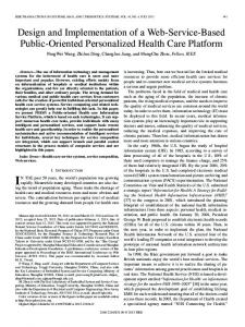
In this section, the CAN message identifier is introduced. The identifier is a part of the CAN message header and plays a very important role in the CAN Event Broadcast Protocol (CEBP). Describing the details of the CAN messages header is beyond the scope of this thesis, as they are only interesting for the lower two ISO OSI layers. Important for the protocols in the ISO OSI layers three to seven (Network Layer to Application Layer; cp. figure 4.6 on page 34), which are the layers, in which the CEBP resides, is only the CAN message identifier. 11 Bit Identifier
Protocol (2) Priority(2)
Node(4)
Port(3)
Data (0−8 Byte)
(x) Bitlength
Figure 4.9.: Identifier of a CAN Packet (Version 2.0A) Figure 4.9 depicts the CAN message identifier for version 2.0A of the CAN bus protocol. The 11 bits are divided into the following four fields (from left to right): 2 bits for the protocol (fixed to 012 for the CEBP), 2 bits for the priority, 4 bits for the node number, and 3 bits for the port number7 . The purpose of these four fields is as follows: 1. The protocol field is always set to 012 for the CAN Event Broadcast Protocol. To give an overview of the other possible values, all four protocols are noted below: 7
Another name for the port number is Event Channel ID, or shorter: ECID
38
4 Architecture, Design and Implementation • A value of 112 chooses the binding protocol, which is not yet implemented. This protocol should later be used by a binding daemon, which makes the binding of event names to ECIDs easier and more dynamic. (More about this in section 6 on page 63.) • A value of 102 selects the point-to-point protocol CANIOP, which is used for standard CORBA communication over the CAN bus. • A value of 012 selects the CAN Event Broadcast Protocol, which is defined in this thesis, and is used to send Events to all listening receivers at once. • A value of 002 finally is reserved for system designers to implement their own functionality. CAN messages sent with this protocol have a higher priority then those of other protocols, thus giving system designers the highest flexibility. 2. The priority field offers four possible priority levels for Events: Starting from the highest level, 002 , over 012 and 102 , to the level with the lowest priority, 112 . The message with the highest priority wins the bus arbitration cycle (as described in section 2.6 on page 18) and is sent first. 3. The node field stores the node number of the sending node. Four bits support a maximum of 24 = 16 different nodes. The node number serves two purposes: • It guarantees that the same Event sent from different nodes never has the same identifier. As mentioned in section 2.6 on page 18, this is a prerequisite for the correct operation of the CAN bus. • It allows the CAN Bus Handler to determine where a received Event comes from. This could later be used for filtering. 4. The port field8 or ECID allows to distinguish the subject of an Event. At the moment, system designers have to decide at setup time, which subject (e.g. oil temperature, or the amount of petrol in the tank) corresponds to which ECID. Later this binding of subjects should be performed by a binding daemon. 29 Bit Identifier
Protocol (2)
Priority(8)
Node(7)
Port(12)
Data (0−8 Byte)
(x) Bitlength
Figure 4.10.: Identifier of a CAN Packet (Version 2.0B) Providing only 11 bits for higher layer protocols, version 2.0A of the CAN bus protocol imposes severe constraints on system resources (i.e. the number of priorities, nodes, and different Events). This problem is overcome when using version 2.0B. 8
named in analogy to the TCP/IP protocol
4.4 CAN Event Broadcast Protocol and CAN Bus Handler Implementation
39
Version 2.0B provides 29 bits, which are used by the CEBP as depicted in figure 4.10 on the preceding page. It supports 28 = 256 different priorities, 27 = 128 nodes, and 212 = 4096 different Events.
4.4.3.
Endianness Issues
In this section the implementation of byte-order handling in the CEBP is discussed. Different computer architectures store multi-byte data types in memory in two different orders: • In little-endian architectures, data is stored with the most significant byte at the highest address. • In big-endian architectures, data is stored with the most significant byte at the lowest address. Imagining the word UNIX stored in a four-byte data type, it would have the following order in memory: Address 00 01 02 03
Little-Endian X I N U
Big-Endian U N I X
Table 4.1.: Little-Endian vs. Big-Endian Why is all this important for a network protocol? Whenever data is exchanged over a network, there is the possibility of a little-endian sender and a big-endian receiver (or vice versa). Somewhere the byte-order of multi-byte data types has to be converted to the byte-order that the receiver understands. There are two possibilities to solve endianness problems: 1. Data sent on the network can have a defined endianness. That means: at the time the network protocol is defined, the person doing this decides whether data sent on the network has to be in little- or big-endian byte-order, or 2. Data sent on the network has the byte-order of the sender and carries additional information about its byte-order (i.e. a bit indicating if it is little- or big-endian). The receiver then has to take care of converting.
40
4 Architecture, Design and Implementation
The design of the CEBP follows the second approach: Data is sent in the byte-order of the sender and the LE9 bit (described in section 4.4.5 on the facing page) gives information about little-endian or big-endian format. This approach has two advantages: • The maximum number of conversions is one (i.e. no conversion if sender and receiver have the same endianness and one if it is different). • In constellations where sender and receiver share the same endianness, but the protocol needs another byte-ordering, data has to be converted twice with the first approach. With the second, no conversion has to be performed.
4.4.4.
Fragmentation and Reassembly
In this section the CEBP’s handling of large data types (i.e. exceeding the length of 7 bytes10 ) is described. The CAN bus protocol allows a maximum of 8 data bytes in a single CAN message. In order to be able to send larger types, a higher layer protocol has to split them into a series of CAN messages at the sender and rejoin these messages on the receiving side. The splitting is called Fragmentation in network terminology and rejoining is called Reassembly.
Sender CORBA::Any (35 Byte)
7 Byte
7 Byte
CAN Packet (8 Byte)
8 Byte
8 Byte
8 Byte
8 Byte
CAN Bus Figure 4.11.: Fragmentation of CORBA::Anys longer than 7 Bytes 9 10
Little-Endian 1 of the allowed 8 data bytes is used for packet information as explained in 4.4.5 on the next page
4.4 CAN Event Broadcast Protocol and CAN Bus Handler Implementation
41
Figure 4.11 on the facing page sketches this process for the CEBP. The sender passes the large data type to the CAN Bus Handler, which splits the data into 7 byte long units. Each of these units is accompanied by an information byte and then sent over the CAN bus. The information byte is described in section 4.4.5. At the side of the receiver, the whole process is inverted. The CAN message, which is marked as containing the first packet of a series, is received and joined with the following messages, which belong to the same data type. The reassembled data is then passed to the Event Channel. More details about the information byte and the typecode are given in the next section.
4.4.5.
Protocol Information in CAN Message Body
In this section the additional CEBP protocol information, which is stored (mainly) in the first data byte of each CAN message, is described. Identifier (11 / 29 Bit)
7 6 5 FP LE
0 TypeCode
Byte 1
Data Length / Data Byte 7
Data (0−6 Byte)
Byte 2
Byte 3−8
FP = First Packet LE = Little Endian
Figure 4.12.: Usage of Data Bytes in a CAN Message Figure 4.12 shows the CAN message identifier on the left, and the 8 data bytes, which each CAN message can transport, on the right. Of particular interest is the left-most of the 8 data bytes. It contains the 2 bits FP and LE, and the TypeCode of the sent CORBA data type: • FP means First Packet and indicates whether this packet is the first in a series of CAN messages. Whenever a message is received, in which this bit is set, a new buffer is allocated on the receiver for concatenating the following messages, in order to reassemble the CORBA data type (see section 4.4.4 on the preceding page). This field is also used in the detection of corrupted data, as explained in section 4.4.6 on the following page. • LE stands for Little-Endian. This bit is set, when the sender’s processor architecture is little-endian (see section 4.4.3 on page 39). It is used at the receiver to decide whether the reassembled data has to be converted. • The TypeCode is a unique identifier defined in the CORBA Specification [6]. Up to version 2.6 of the CORBA Specification there are 34 different CORBA TypeCodes
42
4 Architecture, Design and Implementation defined. This implementation of the CEBP provides a 6 bit field, supporting up to 26 = 64 different TypeCodes.
For most of the CORBA data types, the TypeCode already is information enough to know the length of the data type (i.e. a CORBA::Long is 4 bytes long). Having received the first CAN message, the receiver knows the total length of the data type and can calculate the number of CAN messages needed to reassemble the original CORBA data type. An exception to this rule are the string data types (CORBA::String and CORBA WString): A string can have an arbitrary length. The TypeCode does not provide any information about the data length, in this case. Hence, for strings, the second byte in the first CAN message is used to store the data length. In subsequent messages this information is not needed anymore and the second byte is used to carry part of the actual data, again. As only one byte is used to store the length of a string, in this implementation the length of string data types is limited to 255 bytes. This does not comply with the CORBA standard. It has nevertheless been implemented this way for two reasons: (1) The CEBP loses complexity, and (2) this implementation of CORBA and the implementation of the Event Service is aimed at embedded systems, to which this should constitute a minor problem. Should it prove to be necessary to transfer strings longer than 255 bytes, in the future, this scheme could easily be extended. The value of 255 in the length field (second data byte) could be used to indicate that the string is longer than 254 bytes and the third byte could contain the additional number of bytes. The following bytes (and bytes of subsequent CAN messages) could be used in a similar manner, to allow for unlimited string lengths. By now it should be clear, how CORBA data types are sent over the CAN bus with the CEBP. It is still to be described, what happens if one (or more) of those CAN messages is lost somehow. Although this is extremely unlikely, as explained in section 2.6, provisions for detecting this have been made. These provisions are explained in the following section.
4.4.6.
Detection of Corrupted Data
This section describes the CEBP’s abilities to detect corruption of data due to message loss on the CAN bus. It will furthermore show the protocol’s reaction to such a loss. During development of the protocol, there were problems with corrupted data at the side of the receiver. Reasons for this were (1) lost CAN messages (as explained in section 4.8 on page 54), and (2) the simple fact that a node, which connects to the CAN bus
4.5 Event Service Design Details
43
during the transfer of a long data type, receives only subsequent messages (missing the first one). The solution for synchronising the sending and receiving of Events, which is implemented in the CEBP, is based on the FP bit described in section 4.4.5 on page 41. When a long CORBA data type (i.e. spanning multiple CAN messages) is split into several CAN messages, the FP bit of the first message is set to ”1”; for the subsequent messages belonging to that same data type, it is set to ”0”. The FP bit is used as follows in the two error scenarios:
• When a node is connected to the CAN bus in the middle of a data transfer, it receives only CAN messages with FP = 0. The node discards all messages with FP = 0 and waits until a new transfer is initiated (indicated by FP = 1). The error scenario is over and normal operation starts. • In case of a packet loss during transmission of a longer data type, the receiver does not get the expected number of CAN messages needed to reassemble the CORBA data type. At transmission of the next message from the same sender, the receiver gets a CAN message with FP = 1, while still expecting a subsequent message with FP = 0. The receiving node handles this scenario by resetting the receive buffer allocated for the specific sender, thereby discarding the corrupted CORBA data type, and it starts to reassemble the new CORBA data type. Normal operation continues.
Summarising, corrupted data is not detected until the next data type is transmitted by the same sender and it is then simply discarded.
4.5. Event Service Design Details This section gives insight into implementation details of the Event Service. First, Events and their prioritisation are explained. Then, the priority queue inside the Event Channel and the different possibilities of event dispatching are shown. Subsections 4.5.3 and 4.5.4 introduce two other configurable options concerning the Pull-Model usage of the Event Channel. The last subsection, finally, gives details about how the ESD NTCan library and the corresponding driver are used. This implementation of the CORBA Event Service is based on ROFES [2]. It should be easy, though, to adapt it to other ORB implementations.
44
4 Architecture, Design and Implementation
4.5.1.
Prioritisation of Events
In this subsection, the usage of priorities for sending Events and the mapping of these priorities to the CEBP priorities are explained. Furthermore, questions are answered concerning the API and the effect that priorities have on handling of Events. The OMG Event Service standard [3] does not provide priorities at all. All Events are treated with the same priority. This is acceptable only for non-realtime systems. When time is critical, more important events have to be handled first; even under high load. In a car, the delivery of information about a critical situation (such as a loss of pressure in the breaking system) may not be deferred by routine information about the water temperature or the air conditioning. This implementation of the Event Service, therefore, assigns priorities to Events. Within this implementation of the Event Service, two kinds of priorities are used: 1. CORBA priorities, introduced in the Realtime CORBA standard (see section 2.5 on page 16), are used inside a node. That is, as long as the Event does not travel across the network. The data type RTCORBA::Priority is used to store the priority. It is mapped to a CORBA::Short, which has a length of two bytes. ”0” is defined as the minimum CORBA priority and ”32767” as the maximum. 2. The CEBP priority is used as soon as an Event is sent on the CAN bus. As described in section 4.4.2 on page 37, depending on the CAN bus protocol version, 2 bit (2.0A) or 8 bit (2.0B) fields are provided for storing the priority inside a CAN message. Whenever an Event is sent to the CAN bus, the priority has to be mapped from a CORBA priority to a CEBP priority. At the receiver this CEBP priority has to be mapped to a CORBA priority again. Assigning priorities to Events has two effects: 1. Inside a node, the CORBA priority is used to enqueue the Event inside a priority queue (described in section 4.5.2 on the facing page). Events with the highest priority are then dispatched (i.e. delivered to consumers) first. 2. When sending the Event on the CAN bus, the message with the highest CEBP priority wins the bus arbitration cycle (compare section 2.6 on page 18 and 4.4.2 on page 37); it has precedence over lower priority messages sent from other nodes. Using the prioritisation enhancements of this implementation is only possible through some extensions to the Event Service standard interface. These extensions are described in section 4.6 on page 49.
4.5 Event Service Design Details
4.5.2.
45
Priority Queueing and Threaded Dispatching of Events
In this section the optional priority queueing and dispatching of Events with several threads is explained; implementation and usage details are given. As mentioned in section 4.5.1 on the facing page, for operation under low or medium loads, no additional provisions are necessary for correct operation of the Event Service. Under high loads, though, time critical Events have to be delivered first. Therefore, the Event Channel features a built-in priority queue. Figure 4.13 depicts the internals of the Event Channel. As in all the other illustrations, Events come in to the Event Channel from the left. They are queued in the order of their priority and then Event Dispatch Threads (EDT) take care of delivering them to each consumer.
Event Channel tran
sfer
()
() fer
Event Dispatch Threads
Event Queue transfer()
rs()
ume
cons
static
dynamic
to_ sfer_
tran
transf
er_to_
consu
mers(
)
ns
tra
Figure 4.13.: Main Event Queue with Threaded Dispatching Usage of the priority-based queueing mechanism is optional. At the time of creation, an Event Channel can be configured with or without it. The Event Dispatch Threads make use of a RTCORBA::Threadpool. Hence, the following parameters can be configured: Stack size, the number of statically and dynamically created threads, the default thread priority, if request buffering is allowed, the maximum number of buffered requests, and finally the maximum size of the request buffer. Refer to the RTCORBA Standard, which is part of the CORBA Specification [6], for an in-depth explanation of all the parameters.
4.5.3.
Polling or Thread Blocking in ProxyPullSuppliers
This section explains the implementation of the pull() operation inside the ProxyPullSupplier (see figure 2.3 on page 9 for an overview of the Event Service components).
46
4 Architecture, Design and Implementation
ProxyPullSupplier Event Queue transfer()
pull()
PullConsumer Event
Figure 4.14.: The ProxyPullSupplier and its pull() Operation When a Pull Consumer is connected to a ProxyPullSupplier, and calls the pull() function, it is blocked until a new Event is available at the ProxyPullSupplier. Inside of the Event Service, the ProxyPullSupplier features two possible ways to realise this blocking: • The thread which executes the pull() operation blocks itself and waits until an Event is in the queue. It is then woken up and delivers the Event. In this configuration the processing load is lower, as the thread sleeps. The time to wake up the sleeping thread has to be considered as an additional penalty, though. The overhead of putting a thread to the sleeping state and reawaking it, is only worthwhile if the expected rate in which Events are available is low. • The pull() thread constantly polls the queue if an Event has arrived. The polling interval is configurable. If the polling interval is well tuned to the expected rate, in which Events are available, this configuration delivers fast response time at the cost of higher CPU load. At creation of the ProxyPullSupplier, an optional parameter decides about which of the two aforementioned implementations of the pull() operation is used.
4.5.4.
Polling or Thread Blocking in ProxyPullConsumers
When a Pull Supplier connects to a ProxyPullConsumer, it passively waits until its counterpart pulls for Events. Just like the pull-thread in the ProxyPullSupplier, there are two possibilities again. The pull thread can either: • call the Pull Supplier’s pull operation, which blocks until the Pull Supplier has event data available (see figure 4.15 on the next page), or • check for the presence of a new Event at regular intervals using the Pull Supplier’s try pull operation (see figure 4.16 on the facing page).
4.5 Event Service Design Details
47
1. No Event available: pull PullSupplier
Event
ProxyPullConsumer
Event
ProxyPullConsumer
2. Event available:
PullSupplier
Event
Figure 4.15.: The ProxyPullConsumer in Blocking Mode
1. No Event available: try_pull PullSupplier
sleep
Event
ProxyPullConsumer
2. Event available: try_pull PullSupplier
ProxyPullConsumer
Event Event
Figure 4.16.: The ProxyPullConsumer in Polling mode
48
4 Architecture, Design and Implementation
At creation of the ProxyPullConsumer, it is possible to decide about the blocking or polling operation, and in the second case, the polling interval can be specified. Again, if very fast response times are necessary, if the CPU overhead is tolerable, and if most likely there are a lot of Events coming from this supplier, polling is the better solution. Blocking is better for sporadic Events, where CPU load is more important than very fast response times.
4.5.5.
Usage of ESD Library and Driver for the CAN Bus
The Event Service is constructed in layers of abstraction. This section gives an overview of these layers and explains which layers interact. Furthermore, information is given about which layers of the system are developed in the scope of this thesis and which existing layers were integrated. Suppliers and Consumers Event Channel
CAN Gateway
Thesis
CAN Bus Handler ESD CAN Library ESD CAN Driver
ESD GmbH
CAN Bus Interface Card CAN Bus
Bosch GmbH
Software (developed) Software (provided) Hardware
Figure 4.17.: Interfaces between Components including ESD CAN Library and Driver Figure 4.17 shows the Event Service in a layered view. The bottommost layer is the CAN bus in form of a cable and the CAN bus protocol specification provided by Bosch [4]. The CAN interface card, the corresponding kernel driver and user space library, are provided by ESD. The interface card physically interacts with the bus. It is controlled by the kernel driver. The library offers the functionality of kernel driver to user space programs. The topmost three layers are developed within the scope of this thesis. The CAN Bus Handler is the only component, which interacts with the CAN layers mentioned above. As
4.6 API
49
described in section 4.4.1 on page 35, the CAN Bus Handler implements the CAN Event Broadcast Protocol (CEBP) and thereby provides higher level functionality to the Event Channel and the CAN Gateway. The Event Channel in turn provides the standard CORBA Event Service interface [3] to suppliers and consumers. For demonstration purposes, test suppliers and consumers have been developed.
4.6. API In this section, the extensions to the Standard CORBA Event Service API [3] are listed. A very short summary of the standard API is given together with a reference where to find more information.
4.6.1.
Standard API
A listing of all standard API functions is beyond the scope of this document. Refer to chapter 2 ”Modules and Interfaces” of the Event Service Specification [3] for an in-depth presentation. A very short overview is given, nevertheless: There are two modules that specify the standard funtionality implemented in this version of the Event Service: (1) CosEventComm.idl and (2) CosEventChannelAdmin.idl. In these modules simple push/pull functions and connect/disconnect functions are specified. A specification of an Event Channel Factory is missing.
4.6.2.
Extensions to the standard Event Service API
This Event Service can be operated using only the standard API. The extensions explained in this subsection can be used to specify realtime priorities and to allow creation of Event Channels from remote nodes. When the Event Service is started, the Event Channel Factory provides the following interface to any clients: module ExtendedEventChannelAdmin { interface EventChannelFactory { CosEventChannelAdmin::EventChannel create_channel (); CosEventChannelAdmin::EventChannel create_channel_can ( in CORBA::Short ec_id); CosEventChannelAdmin::EventChannel
50
4 Architecture, Design and Implementation create_channel_with_parms ( in CORBA::Boolean direct_transfer, in CORBA::ULong edt_stacksize, in CORBA::UShort edt_static_threads, in CORBA::UShort edt_dynamic_threads, in RTCORBA::Priority edt_default_priority, in CORBA::Boolean edt_allow_request_buffering, in CORBA::UShort edt_max_buffered_requests, in CORBA::UShort edt_max_request_buffer_size ); CosEventChannelAdmin::EventChannel create_channel_can_with_parms ( in CORBA::Short ec_id, in CORBA::Boolean direct_transfer, in CORBA::ULong edt_stacksize, in CORBA::UShort edt_static_threads, in CORBA::UShort edt_dynamic_threads, in RTCORBA::Priority edt_default_priority, in CORBA::Boolean edt_allow_request_buffering, in CORBA::UShort edt_max_buffered_requests, in CORBA::UShort edt_max_request_buffer_size ); };
}; As the above excerpt shows, the Event Channel Factory allows to create standard Event Channels and those for the CAN bus, which use the CEBP. Furthermore, it allows to specify realtime parameters for these Event Channels. Apart from the Event Channel Factory, functions have been added to the interfaces of (1) the SupplierAdmin, (2) the ConsumerAdmin, (3) the ProxyPushSupplier, (4) the ProxyPullConsumer, and (5) the PushConsumer. They are shown in the following listing: 1. The SupplierAdmin provides the possibility to specify realtime parameters when creating a ProxyPullConsumer (compare section 4.5.4 on page 46): module CosEventChannelAdmin { interface SupplierAdmin { ProxyPullConsumer obtain_pull_consumer_with_parms( in CORBA::Boolean poll_while_pulling, in CORBA::ULong polling_interval ); }; };
4.6 API
51
2. The ConsumerAdmin offers two new functions allowing to specify realtime parameters again and to obtain a ProxyPushSupplier that does not deliver Events using the standard push function, but rather the push with priority function. This is important if Event Channels should be federated (see figure 2.8 on page 15) and still pass along the Event’s priority: module CosEventChannelAdmin { interface ConsumerAdmin { ProxyPushSupplier obtain_push_supplier_with_priority(); ProxyPullSupplier obtain_pull_supplier_with_parms( in CORBA::Boolean poll_while_pulling, in CORBA::ULong polling_interval, in CORBA::ULong max_queue_size ); }; }; 3. The ProxyPushSupplier’s interface is extended by two functions. These allow the PushConsumer, which is connected to it, to temporarily refrain from accepting events without having to disconnect and reconnect: module CosEventChannelAdmin { interface ProxyPushSupplier: CosEventComm::PushSupplier { void suspend_connection() raises(ConnectionAlreadyInactive, NotConnected); void resume_connection() raises(ConnectionAlreadyActive, NotConnected); }; }; 4. The ProxyPullConsumer offers the same new functions explained above. A connected PullSupplier can temporarily stop the ProxyPullConsumer from pulling for new events: module CosEventChannelAdmin { interface ProxyPullConsumer: CosEventComm::PullConsumer { void suspend_connection() raises(ConnectionAlreadyInactive, NotConnected); void resume_connection() raises(ConnectionAlreadyActive, NotConnected); }; };
52
4 Architecture, Design and Implementation 5. The PushConsumer, finally, is extended by a function, which allows it to specify the priority of the Event it pushes: module CosEventComm { interface PushConsumer { void push_with_priority ( in any data, in RTCORBA::Priority priority) raises(Disconnected); }; };
4.7. Implementation of Basic Functionality In this section, basic functionality necessary for the implementation of the ROFES Event Service is described.
4.7.1.
Priority Queue
The main component inside the Event Channel is the Event Queue. When using the realtime features of this Event Service, incoming Events are first stored in the Event Queue and then forwarded to all subscribed consumers. First
Last
Data (4)
Data(15)
Data(100)
Previous
Previous
Previous
Next
Next
Next
New
Dequeue
ue
Enque
Data(50) Previous Next
Figure 4.18.: The Priority Queue
4.7 Implementation of Basic Functionality
53
For queueing Events in the order of their priority, a priority queue is needed. The priority queue implemented here, is based on a doubly linked list. That is a data structure, in which each element contains a link to the next and the previous element, thus forming a bidirectional linked list (see figure 4.18 on the preceding page). This implementation of a priority queue inserts the incoming Event at the correct place. Later, the Event with the highest priority can be easily dequeued by taking the last element. Comparison of elements is done by the > operator, which can be overloaded to compare any types of elements. The data stored in each element is an Event Struct (see figure 4.8 on page 37) and the > operator is overloaded to compare the priorities inside the struct.
4.7.2.
Readers/Writer Locks
When different threads access the same data structures, these structures have to be protected from concurrent accesses. The usual technique used in this case is a mutex (variable for mutual exclusion). The mutex guarantees that exactly one thread can access (read from or write to) a data structure at a given time. Inside the Event Channel there are lists for keeping track of consumers and suppliers, which are connected to the channel. Most of the time (i.e when Events are sent through the Event Channel), these lists only have to be read in order to determine, which consumers to forward Events to. Writing is only needed when new consumers or suppliers connect to the Event Channel. With mutexes, only a single thread would be allowed to access a list; the other threads would have to wait until the first one granted access again. No difference would be made between threads requiring read access only (as is the case with the sending threads) and threads requiring write access (threads executing the connect function). Access would be granted to one thread after the other, only. For optimisation purposes, in this implementation of the Event Service, another means of protection was needed. One, that granted read access to many threads and write access to one thread exclusively. The readers/writer lock, implemented in this thesis, provides the necessary functionality. In this specific implementation, writers have precedence over readers. This means that, whenever a writer tries to acquire a write-lock to a data structure, readers trying to acquire a read-lock will be queued behind the writer. The writer has to wait until any readers already holding a read-lock give back the lock, then it gets the write-lock. New readers, are not allowed to enter the restricted area and read together with the other readers; they have to let the writer enter and leave first.
54
4 Architecture, Design and Implementation
4.8. Problems and Solutions There were a lot of problems particularly during the implementation phase of this project. Some of them, that costed especially much time, are presented below. A big problem was that of lost CAN messages on the CAN bus. After some experimenting, the problem was tracked down to node on the bus (which was not currently involved in testing), whose CAN bus interface card was not initialised at all. Instead of doing nothing, it seemed to be the reason of the packet loss. Removing the node solved the problem. The means for detection of corrupted data (described in section 4.4.6 on page 42) were introduced in this context. The Event Queue (depicted in figure 4.13 on page 45) and especially the send queue of the CAN bus driver overflow when sending Events to them at a very high rate. Connecting many PushSuppliers to the Event Channel, their sending rate had to be reduced. The debugger (gdb) presented another very time consuming problem. On the development systems (described in section 4.1 on page 27), it did not work together with the pthreads library, when the latter was dynamically linked. For debugging with the gdb, the whole project had to be recompiled as a static version. This is a time consuming process, which is otherwise avoided. Last but not least, the underlying ROFES implementation of CORBA, is under heavy development. Additional functionality had to be implemented during the development of the Event Service and sometimes the CORBA implementation still had some incorrectnesses detected during tests with the Event Service.
5. Benchmarks – Latency Measurement
In this chapter the Software designed and implemented within the scope of the diploma thesis is put under test. Different setups are measured for latency. Furthermore, the code size as one of the major design goals is presented. All the following benchmarks have been run on the three computers (described in section 4.2 on page 27), which are equipped with a CAN bus interface card. The code of the benchmarks conducted for the Event Channel with priority queueing enabled can be found in the Appendix A on page 65. For measurement over the Ethernet, three computers were used.
PC1
PC2
Ethernet
PC3
Setup 1: Supplier, Channel, Consumer Setup 2: Supplier
Channel, Consumer
Setup 3: Supplier
Channel
Consumer
Event Flow
Figure 5.1.: Setup of Components for the first two Benchmarks As figure 5.1 shows, the three setups differ in the placement of components (supplier, channel, consumer) on the three computers. • In setup 1, all three components are located on one computer. The Event does not have to cross the network on the way to the consumer. • In setup 2, the supplier is located on one computer, channel and consumer are located on another. One network transfer is necessary.
56
5 Benchmarks – Latency Measurement • In setup 3, all components are located on different nodes. The Event has to cross the network twice.
For the next benchmarks, the Event Channel has been compiled without support for the CAN bus, with queueing disabled. The ProxyPushConsumer’s push() function, which is executed by the supplier, returns only after the Event is delivered to the consumer (with queueing enabled, it returns already after the Event is delivered to the channel).
5.1. Priority Queueing disabled The first benchmark investigates, how different numbers of network transfers influence the latency of Event passing. 700 setup 1 setup 2 setup 3
average latency/[usec]
680
660
640
620
600
0
1
2 setup
3
4
Figure 5.2.: Latency over Ethernet with Direct Transfer enabled Figure 5.2 shows the average latency for the ProxyPushConsumer’s push() function. A CORBA::Any is sent containing a CORBA::Short. The numbers represent the average of 1000 runs, which were executed in order to minimise the effect of temporary and sporadic delays. Time is measured between the execution and returning of the ProxyPushConsumer’s push() function. Here, the push() function returns, when the Event is delivered to every connected PushConsumer. Setup 1 delivers the smallest latency, as all communication is local. In setup 2, the supplier sends its request together with the event data to the Event Channel over the network. Calling the consumer’s push() function is a local operation. The acknowledgement sent back to the supplier has to travel over the network again. Hence, two network transfers
5.1 Priority Queueing disabled
57
are necessary: the first one with event data and the second one only with the acknowledgement. This explains the increased latency. In setup 3, four network transfers are necessary: two on the way to the consumer and two acknowledgements on the way back. Again, latency increases. The next diagram (figure 5.3) examines the effect, which different data sizes have on the latency.
average latency/[usec]
4096
setup 1 setup 2 setup 3
2048
1024
512 4
16
64 256 data size/[bytes]
1024
4096
Figure 5.3.: Latency over Ethernet for different Data Sizes Events with growing length were sent using the three setups described above. For the purpose of constructing event data of arbitrary lengths, CORBA::Strings have been used. Figure 5.3 nicely shows three effects: 1. As expected, latency for setup 1 (which requires the smallest number of network transfers) is always smaller than latency for setup 2 (with setup 3 resulting in the highest latency values). This effect is independent of the data size. 2. With data sizes between 128 bytes and 8192 bytes, latency increases linearly with the number of bytes. This happens for all three setups. 3. For data sizes smaller than 128 bytes, other factors are dominant. There is no measurable difference in latency between sending of a two-byte data type, and a 128-byte data type. Figure 5.4 on the following page shows effects of the underlying ORB implementation. The expected results are yielded for data sizes smaller than 16kB. If data sizes
58
5 Benchmarks – Latency Measurement 131072
setup 1 setup 2 setup 3
65536
average latency/[usec]
32768 16384 8192 4096 2048 1024 512
4
16
64
256 1024 data size/[bytes]
4096
16384
65536
262144
Figure 5.4.: Latency comparison for different Data Sizes, other Effects greater than 16kB are sent, the underlying CORBA heavily influences latency. Further investigation showed that the ORB was configured with an IIOP message buffer size of 16kB. As soon as the size of an Event exceeds this length, it has to be split into several messages before sending, and must be reassembled on the side of the receiver. This explains the big increase of latency, when crossing the 16kB boundary. When larger Events are sent, the three graphs converge. It does not make any difference anymore, if the data is sent over the network once or twice. That means that the time, which is spent sending data over the network becomes negligible in comparison to the time spent in fragmentation and reassembly. Calculation demands move the bottle neck from the network onto the processing power of attached nodes. Note, that ROFES and the ROFES Event Service are designed for embedded systems and are therefore not optimised for sending huge messages.
5.2. Priority Queueing enabled The following benchmarks were run using a version of the Event Channel with enabled priority queueing and threaded dispatching of Events. A measurement as in the previous subsection is not possible, because the priority queue introduces an asynchrony. When a supplier executes the push() function of the ProxyPushConsumer, the function call returns as soon as the Event is queued in the Event Channel. As explained above, with priority queueing disabled, it returned after the Event had been delivered to every connected Push-
5.2 Priority Queueing enabled
59
Consumer. ping
Event Service
pong
time start
push() PushSupplier
push() PushConsumer
EC
EC
push() PushConsumer
push() PushSupplier
time stop
Figure 5.5.: Setup of Components for Benchmarks with Queueing enabled For the above reasons, the following setup was chosen (see figure 5.5). The PushSupplier and PushConsumer on the left hand side, which execute the time measurement functions are implemented in one small program (i.e. they are always on the same node). The same applies to the PushConsumer and PushSupplier on the right hand side and to the two Event Channels. As depicted in figure 5.5, the clock for latency measurement is started before the PushSupplier on the left hand side executes the push() function; it is stopped, when the push() function of the PushConsumer on the left is executed. This determines a round-trip time. To obtain the latency, which is shown in figure 5.6 on the following page, this value has to be divided by two. Due to the different methods used for calculating the latency, figure 5.3 on page 57 and figure 5.6 on the following page can not be directly compared. Figure 5.6 on the next page shows latency values measured with Event Channels with queueing enabled. As mentioned above, queueing introduces an asynchrony. A supplier executing the proxy’s push() function is no longer (synchronously) blocked, until the Event has reached its final destination(s) (i.e. all consumers connected to the Event Channel). The function call returns after the Event has been queued in the Event Channel. This has two effects: • The supplier is not blocked for an equally long period as it was with the Event Channel configured for direct transfer. It is free to continue with other operations
60
5 Benchmarks – Latency Measurement 4096
setup 1 setup 2 setup 3
average latency/[usec]
2048
1024
512
256
4
16
64 256 data size/[bytes]
1024
4096
Figure 5.6.: Measurement of Latency with Queueing enabled or push the next event after a shorter time of blocking, enabling it to send a series of Events at a higher rate. • The supplier is no longer (synchronously) informed if the initiated operation (pushing the Event to consumers) succeeded completely. That is, if the Event is correctly received by all connected consumers. If this functionality is required, the Event Channel should be configured for synchronous delivery. As an alternative, this can easily be achieved by setting up a second Event Channel for acknowledgement messages. Figure 5.6 yields some interesting results. For data sizes below 256 bytes, no difference in latency between setup 1, setup 2 and setup 3 can be measured. The influence that the number of network transfers has on latency seems to be rather small when sending small data sizes (compared to the synchronous setup, where more network transfers meant higher latency even for small data sizes – compare figure 5.3 on page 57). This can be explained as follows: In contrast to the synchronous benchmark, acknowledgement transfers do not delay the transfer of Events to consumers, as they happen in parallel to forwarding of Events. Acknowledgement times therefore do not add to the measured latency. For small data sizes, acknowledgement messages are almost as big as the event data itself. The number of messages that add to the measured latency are therefore halved. This is a bit complicated and will therefore be explained in greater detail. With queueing disabled, event data is sent from the supplier to the Event Channel,
5.2 Priority Queueing enabled
61
and from the Event Channel to the consumer. Then, the acknowledgement has to be sent the same way back (consumer, Event Channel, supplier). All this happens sequentially; especially sending of acknowledgements adds to the latency measured in section 5.1. In contrast to that, with the asynchronous setup, event data is sent from the supplier to the Event Channel, and while the Event Channel forwards the data to the consumer, the acknowledgement is already sent back to the supplier. The same happens on the way back: The supplier of the Pong component (refer to figure 5.5 on page 59) forwards the event data in parallel to Pong’s consumer returning an acknowledgement message to the first event channel. We can conclude that with priority queueing enabled, the influence that network transfers have on latency are negligible, when transferring small data sizes. As can be seen on the right hand side of the diagram, the number of network transfers regains importance when sending data sizes of 1024 bytes and above. There is a big difference in latency between sending an Event of the same size with setup 1, with setup 2, or with setup 3.
62
5 Benchmarks – Latency Measurement
6. Conclusions and Outlook
Within the scope of this thesis, a light-weight implementation of the CORBA Event Service has been developed. It provides realtime extensions and is largely configurable. The Event Channel, which is the heart of the Event Service can be configured to queue Events, making communication even more decoupled. Suppliers of data can not only be ignorant of any consumers interested in their data (which is the main aim of the Event Service in general), they do not even have to wait until delivery of event data has been completed (compare section 5.2 on page 58). This ensures very short times, in which suppliers are blocked for sending of data. When the additional transactional acknowledgement is needed, the Event Service can be configured for direct transfer of Events. Then, the push() function issued by a supplier does not return until the Event is delivered to every connected consumer. A protocol for the effective distribution of event data over the CAN bus has been developed and implemented. Event multiplexing, which is conventionally done by Event Channels only, is complemented with multiplexing of Events by the CAN bus. This has the advantage that Events directed to any number of consumers on other nodes have to be sent only once over the bus, thus reducing bus load and allowing other Events to be sent during the gained idle time. The CAN Event Broadcast Protocol CEBP as it is called makes extensive use of the CAN bus features for multiplexing and prioritisation of Events. Using two bits of the CAN message identifier to distinguish it from other higher level protocols on the CAN bus, the CEBP cooperates flawlessly with ongoing efforts to develop a standardised version of IOP for the CAN bus. Together with ROFES [2], a realtime ORB for embedded systems, which is developed at the Chair of Operating Systems at the University of Technology Aachen, this implementation of the Event Service provides a platform for the growing market of so called Distributed Realtime Embedded (DRE) systems. Small code size and fine-grained control of many realtime parameters are prominent features. To make the Realtime Event Service for the CAN bus even more flexible and to make systems developed on top of it easier to use and maintain, a binding daemon should be
64
6 Conclusions and Outlook
implemented that dynamically maps logical node and channel names to physical ones, as proposed in [22]. Definition of the CEBP already assigns two bits of the CAN message identifier to such a binding protocol (compare [24]). The OMG is in the process of specifying a Realtime Notification Service. This is an enhanced version of the Notification Service [12] as described in section 2.3 on page 13. It offers a superset of the functionality provided by the Event Service and should yield even better manageability for more complex communication scenarios. This implementation of a Realtime CORBA Event Service can be used as basis for the construction of such a service.
A. Appendix – Source Code of Benchmarks
A.1. Source of the Channelserver After the Event Service is started, the channelserver is run to set up an Event Channel. The channelserver is used in all benchmarks and demonstrates usage of the Event Channel Factory, which is the interface that the started Event Service provides. /*********************** project headers **********************/ #include #include #include #include #include const char* ecf_filename = "ecf.ior"; const char* ec_filename = "ec.ior"; CORBA::ULong channel_number = 3; /*! WHAT THIS FILE DOES: * The ChannelServer sets up the EventChannel. If there is no * EventChannel, it locates the EventChannelFactory, creates * an EventChannel, and saves its reference to a file. */ // ----------------------- The Main Program -------------------extern "C" int main(int argc, char* argv[]) { ExtendedEventChannelAdmin::EventChannelFactory_var factory; CosEventChannelAdmin::EventChannel_var channel; // Initialize the ORB CORBA::ORB_var orb = CORBA::ORB_init(argc, argv, "orb");
66
A Appendix – Source Code of Benchmarks
// Get reference to the EventChannelFactory object // (The Event Channel Factory is the primary interface of // the Event Service) fprintf(stderr, "Getting reference to EventChannelFactory.\n"); char buf[1024]; FILE* ecf_fd = fopen(ecf_filename, "r"); if (ecf_fd == NULL) { perror("fopen"); exit(1); } fscanf(ecf_fd, "%s", buf); fclose(ecf_fd); CORBA::String_var ecf_ref((const char *) buf); CORBA::Object_var ecf_obj = orb->string_to_object(ecf_ref); factory = ExtendedEventChannelAdmin:: EventChannelFactory::_narrow(ecf_obj); // Create EventChannel fprintf(stderr, "Creating EventChannel.\n"); //channel = factory->create_channel(); channel = factory->create_channel_can(channel_number); printf("Creating IOR\n"); // ... and save the reference to file CORBA::String_var ec_ior = orb->object_to_string (channel); printf("Writing IOR to file\n"); FILE* ec_fd = fopen(ec_filename, "w"); if (ec_fd == NULL) { perror("fopen"); exit(1); } fprintf(stderr, "ec_ior = %s\n\n", (char*) ec_ior); fprintf(ec_fd, "%s", (char*) ec_ior); fclose(ec_fd); fprintf(stderr, "EventChannel up and running.\n"); // ... or register channel with a naming service }
A.2 Source of the Asynchronous Ping Example
67
A.2. Source of the Asynchronous Ping Example This is a complete version of the source code for the Ping component (depicted in 5.5 on page 59). It contains all steps necessary to connect to an existing Event Channel and may therefore serve as a reference. Moreover, it shows exactly how latency measurement is done. /******************* project headers **************************/ #include #include #include #include #include #include const char* result_filename = "latency_ping_pong_times_n_nodes"; const char* ec_filename = "ec.ior"; const char* ec_back_filename = "ec_back.ior"; sem_t send_sem; // Ensure next sending is after receiving hrtime_t t1 = 0; // send time hrtime_t t2 = 0; // receive time hrtime_t average = 0; // average time of ping-pong const int number_of_runs = 10000; /*! WHAT THIS FILE DOES: Ping pushes data to the Event Channel, waits until Pong sends data back. When data is received, it calculates the round trip time and divides it by 2 to get the latency. */ /* PING */ class Ping : public CosEventComm::POA_PushSupplier { public: Ping() {} void disconnect_push_supplier(); }; void Ping::disconnect_push_supplier() { fprintf(stderr, "Ping::disconnect_push_supplier() called"); } /* PONGRECEIVER */
68
A Appendix – Source Code of Benchmarks
class PongReceiver : public CosEventComm::POA_PushConsumer { public: PongReceiver() {} void push(const CORBA::Any& data); void disconnect_push_consumer(); private: CosEventChannelAdmin::ProxyPushSupplier_var supplier; }; void PongReceiver::push(const CORBA::Any& data) { t2 = gethrtime(); average += (t2-t1)/1000; sem_post(&send_sem); } void PongReceiver::disconnect_push_consumer() { fprintf(stderr, "PongReceiver::disconnect_push_consumer() called"); }
// ----------------------- The Main Program -------------------extern "C" int main(int __argc, char* __argv[]) { CosEventChannelAdmin::EventChannel_var channel; CosEventChannelAdmin::EventChannel_var channel_back; CosEventChannelAdmin::SupplierAdmin_var supp_admin; CosEventChannelAdmin::ConsumerAdmin_var cons_admin_back; CosEventChannelAdmin::ProxyPushConsumer_var consumer; CosEventChannelAdmin::ProxyPushSupplier_var supplier_back; // Initialise the Semaphore sem_init(&send_sem, 0, 0); // Initialize the ORB CORBA::ORB_var orb = CORBA::ORB_init(__argc, __argv, "orb"); // open output file for results FILE* result_fd = fopen(result_filename, "w"); // Get reference to the EventChannel object char buf[1024]; FILE* ec_fd = fopen(ec_filename, "r"); if (ec_fd == NULL) { perror("fopen");
A.2 Source of the Asynchronous Ping Example
69
exit(1); } fscanf(ec_fd, "%s", buf); fclose(ec_fd); CORBA::String_var ec_ref((const char *) buf); CORBA::Object_var ec_obj = orb->string_to_object(ec_ref); channel = CosEventChannelAdmin::EventChannel::_narrow(ec_obj); // Get reference to the EventChannel_back object FILE* ec_back_fd = fopen(ec_back_filename, "r"); if (ec_back_fd == NULL) { perror("fopen"); exit(1); } fscanf(ec_back_fd, "%s", buf); fclose(ec_back_fd); CORBA::String_var ec_back_ref((const char *) buf); CORBA::Object_var ec_back_obj = orb->string_to_object(ec_back_ref); channel_back = CosEventChannelAdmin:: EventChannel::_narrow(ec_back_obj); // Finally start the first server/supplier fprintf(stderr, "PushSupplier wird gestartet.\n"); supp_admin = channel->for_suppliers(); fprintf(stderr, "SupplierAdmin obtained.\n"); cons_admin_back = channel_back->for_consumers(); fprintf(stderr, "ConsumerAdmin obtained from return channel.\n"); consumer = supp_admin->obtain_push_consumer(); fprintf(stderr, "ProxyPushConsumer obtained.\n"); supplier_back = cons_admin_back->obtain_push_supplier(); fprintf(stderr, "ProxyPushSupplier obtained from return channel.\n"); // Obtain a reference to the RootPOA and its Manager CORBA::Object_var poaobj = orb->resolve_initial_references("RootPOA");
70
A Appendix – Source Code of Benchmarks PortableServer::POA_var poa = PortableServer::POA::_narrow(poaobj); PortableServer::POAManager_ptr mgr = poa->the_POAManager(); // Create a Ping object Ping ping; fprintf(stderr, "Ping created.\n"); // Create a PongReceiver object PongReceiver pong; fprintf(stderr, "Pong created.\n"); // Activate the Servants PortableServer::ObjectId oid = poa->activate_object(&ping); fprintf(stderr, "Ping activated: ObjectId = %u\n", (unsigned) oid); oid = poa->activate_object(&pong); fprintf(stderr, "Pong activated: ObjectId = %u\n", (unsigned) oid); // Register Ping consumer->connect_push_supplier((&ping)->_this()); fprintf(stderr, "Ping connected to the channel as Supplier...\n\n"); supplier_back->connect_push_consumer((&pong)->_this()); fprintf(stderr, "PongReceiver connected to the return channel as Consumer...\n\n"); // Activate the POA and start running mgr->activate(); fprintf(stderr, "Objects ready to service requests: mgr->activate()...\n\n"); // Start pushing event fprintf(stderr, "Ping starts pushing event.\n\n"); CORBA::Any data; CORBA::Short Short_data = 0; data push(data); } // Create a Pong object
72
A Appendix – Source Code of Benchmarks
Pong pong; /* PINGRECEIVER */ class PingReceiver : public CosEventComm::POA_PushConsumer { public: PingReceiver() {} void push(const CORBA::Any& data); void disconnect_push_consumer(); private: CosEventChannelAdmin::ProxyPushSupplier_var supplier; CORBA::Short Short_data; }; void PingReceiver::push(const CORBA::Any& data) { //fprintf(stderr, "Ping received, pushing back\n"); pong.send(data); } void PingReceiver::disconnect_push_consumer() { fprintf(stderr, "PingReceiver::disconnect_push_consumer() called\n"); } // ----------------------- The Main Program -------------------extern "C" int main(int __argc, char* __argv[]) { CosEventChannelAdmin::EventChannel_var channel; CosEventChannelAdmin::EventChannel_var channel_back; CosEventChannelAdmin::ConsumerAdmin_var cons_admin; CosEventChannelAdmin::SupplierAdmin_var supp_admin_back; CosEventChannelAdmin::ProxyPushSupplier_var supplier; CosEventChannelAdmin::ProxyPushConsumer_var consumer_back; // Initialize the ORB CORBA::ORB_var orb = CORBA::ORB_init(__argc, __argv, "orb"); // Get reference to the EventChannel object // (parts left out; see ping.cpp for details) channel = CosEventChannelAdmin::EventChannel::_narrow(ec_obj); // Get reference to the EventChannel_back object // (parts left out; see ping.cpp for details) channel_back = CosEventChannelAdmin:: EventChannel::_narrow(ec_back_obj);
A.3 Source of the Asynchronous Pong Example
73
// Finally start the first server/supplier fprintf(stderr, "Pong wird gestartet.\n"); // Create a PingReceiver object PingReceiver ping; fprintf(stderr, "PingReceiver created.\n"); cons_admin = channel->for_consumers(); fprintf(stderr, "ConsumerAdmin obtained.\n"); supp_admin_back = channel_back->for_suppliers(); fprintf(stderr, "SupplierAdmin obtained for return channel.\n"); supplier = cons_admin->obtain_push_supplier(); fprintf(stderr, "ProxyPushConsumer obtained.\n"); pong.consumer_back = supp_admin_back->obtain_push_consumer(); fprintf(stderr, "ProxyPushConsumer obtained for return channel.\n"); // Obtain a reference to the RootPOA and its Manager CORBA::Object_var poaobj = orb->resolve_initial_references("RootPOA"); PortableServer::POA_var poa = PortableServer::POA::_narrow(poaobj); PortableServer::POAManager_ptr mgr = poa->the_POAManager(); // Activate the Servants PortableServer::ObjectId oid = poa->activate_object(&ping); fprintf(stderr, "PingReceiver activated: ObjectId = %u\n", (unsigned) oid); oid = poa->activate_object(&pong); fprintf(stderr, "Pong activated: ObjectId = %u\n", (unsigned) oid); // Register Pong pong.consumer_back->connect_push_supplier((&pong)->_this()); fprintf(stderr, "Pong connected as Supplier...\n\n"); supplier->connect_push_consumer((&ping)->_this()); fprintf(stderr, "PingReceiver connected as Consumer...\n\n");
74
A Appendix – Source Code of Benchmarks // Activate the POA and start running mgr->activate(); fprintf(stderr, "Pong ready to service requests: mgr->activate()...\n\n"); // Give control of the process to the orb fprintf(stderr, "Pong Running...\n\n"); orb->run();
}
Glossary
ACE
Adaptive Communication Environment
AMI
Asynchronous Method Invocation
BOA
Basic Object Adapter
Broadcast
Sending of a message addressed to all connected nodes
CAN
Controller Area network
CEBP
CAN Event Broadcast Protocol
COM
Common Object Model
CORBA
Common Object Request Broker Architecture
CRC
Cyclic Redundancy Check
CSMA/CA
Carrier Sense Multiple Access/Collision Avoidance
CSMA/CD
Carrier Sense Multiple Access/Collision Detection
DCOM
Distributed Common Object Model
DOS
Distributed Object Systems
DRE Systems Distributed Real-time Embedded Systems EC
Event Channel
ECF
Event Channel Factory
EDT
Event Dispatch Thread
IDL
Interface Definition Language
IIOP
Internet Inter-ORB Protocol
76
Glossary
MICO
MICO is COrba – Open source implementation of the CORBA specification, which has originally been developed at the University of Frankfurt/Main
Multicast
Sending of a message addressed to a group of connect nodes
OMA
Object Management Architecture
OMG
The Object Management Group is an open membership, not-for-profit consortium that produces and maintains computer industry specifications for interoperable enterprise applications
OOP
Object Oriented Programming
ORB
Object Request Broker
OS
Operating System
POA
Portable Object Adapter
QoS
Quality of Service
RMI
Remote Method Invocation
ROFES
Realtime ORB For Embedded Systems
RTCORBA
Realtime CORBA
TAO
The ACE ORB – Open source implementation of the CORBA specification developed at the Washington University St. Louis
List of Figures
2.1. Object Management Group’s Open Management Architecture . . . . . .
4
2.2. A Request passing from Client to Servant . . . . . . . . . . . . . . . . .
6
2.3. General Structure of the Event Service . . . . . . . . . . . . . . . . . . .
9
2.4. Structure of the CORBA::Any . . . . . . . . . . . . . . . . . . . . . . .
11
2.5. Oil Temperature Sensor pushing Event Data to Consumers . . . . . . . .
11
2.6. Flow of Temperature Data from Sensor to Consumers . . . . . . . . . . .
13
2.7. General Structure of the Notification Service . . . . . . . . . . . . . . . .
13
2.8. Federation of Event Channels . . . . . . . . . . . . . . . . . . . . . . . .
15
3.1. Overall Communication System’s Architecture . . . . . . . . . . . . . .
24
4.1. General Setup of the Centralised Event Service for the Ethernet . . . . . .
29
4.2. Setup of Nodes with Distributed Event Service for the CAN Bus . . . . .
30
4.3. Multiplexing of Event Data . . . . . . . . . . . . . . . . . . . . . . . . .
31
4.4. Multiplexing of Event Data by CAN Bus . . . . . . . . . . . . . . . . . .
32
4.5. Components of Distributed CAN Event Service and their Interactions . .
33
4.6. ISO OSI 7 Layer Model with CAN Event Broadcast Protocol (CEBP) . .
34
4.7. The CAN Bus Handler in its Environment . . . . . . . . . . . . . . . . .
35
4.8. The Event Struct . . . . . . . . . . . . . . . . . . . . . . . . . . . . . .
37
4.9. Identifier of a CAN Packet (Version 2.0A) . . . . . . . . . . . . . . . . .
37
78
List of Figures 4.10. Identifier of a CAN Packet (Version 2.0B) . . . . . . . . . . . . . . . . .
38
4.11. Fragmentation of CORBA::Anys longer than 7 Bytes . . . . . . . . . . .
40
4.12. Usage of Data Bytes in a CAN Message . . . . . . . . . . . . . . . . . .
41
4.13. Main Event Queue with Threaded Dispatching . . . . . . . . . . . . . . .
45
4.14. The ProxyPullSupplier and its pull() Operation . . . . . . . . . . . . . .
46
4.15. The ProxyPullConsumer in Blocking Mode . . . . . . . . . . . . . . . .
47
4.16. The ProxyPullConsumer in Polling mode . . . . . . . . . . . . . . . . .
47
4.17. Interfaces between Components including ESD CAN Library and Driver .
48
4.18. The Priority Queue . . . . . . . . . . . . . . . . . . . . . . . . . . . . .
52
5.1. Setup of Components for the first two Benchmarks . . . . . . . . . . . .
55
5.2. Latency over Ethernet with Direct Transfer enabled . . . . . . . . . . . .
56
5.3. Latency over Ethernet for different Data Sizes . . . . . . . . . . . . . . .
57
5.4. Latency comparison for different Data Sizes, other Effects . . . . . . . .
58
5.5. Setup of Components for Benchmarks with Queueing enabled . . . . . .
59
5.6. Measurement of Latency with Queueing enabled . . . . . . . . . . . . .
60
Bibliography
[1] Douglas C. Schmidt and Carlos O’Ryan. Patterns and Performance of Distributed Real-time and Embedded Publisher/Subscriber Architectures. Journal of Systems and Software, 2002. 1, 16, 22 [2] S. Lankes, M. Pfeiffer, and T. Bemmerl. Design and Implementation of a SCI-based Real-Time CORBA. In 4th IEEE International Symposium on Object-Oriented Real-Time Distributed Computing (ISORC 2001), Magdeburg, Germany, May 2001. 1, 7, 16, 43, 63 [3] OMG. Event Service Specification. Object Management Group, v. 1.1 edition, March 2001. 1, 8, 21, 22, 24, 44, 49 [4] Robert Bosch GmbH, Postfach 50, D-7000 Stuttgart 1. CAN Specification, version 2.0 edition, September 1991. 2, 19, 20, 23, 48 [5] Steve Vinoski. CORBA: Integrating Diverse Applications Within Distributed Heterogeneous Environments. IEEE Communications Magazine, 14(2), 1997. 7 [6] OMG. CORBA Specification. OMG, v. 2.6 edition, December 2001. 7, 16, 41, 45 [7] David Curtis. Java, RMI and CORBA. http://www.omg.org/library/wpjava.html, 1997. 7 [8] SUN Microsystems Inc. JAVA Remote Method Invocation - Distributed Computing For JAVA. http://java.sun.com/marketing/collateral/javarmi.html, 2002. 8 [9] Gopalan Suresh Raj. A Detailed Comparison of Corba, DCOM and Java/RMI. http://my.execpc.com/ gopalan/misc/compare.html, September 1998. 8 [10] Emerald Chung, Yennun Huang, Shalini Yajnik, Deron Liang, Joanne C. Shih, Chung-Yih Wang, and Yi-Min Wang. DCOM and CORBA side by side, step by step and layer by layer. 1997. 8 [11] Microsoft Corporation. DCOM Technical Overview. http://msdn.microsoft.com/library/en-us/dndcom/html/msdn dcomtec.asp, November 1996. 8
80
Bibliography
[12] OMG. Notification Service Specification. Object Management Group, v. 1.0.1 edition, August 2002. 13, 64 [13] Thomas Bemmerl and Michael Pfeiffer. Realzeit Systeme I. Umdruck zur Vorlesung, October 1999. 15, 16 [14] Prof.Dr. Hermann Kopetz. Informatik Handbuch, chapter Echtzeitsysteme, pages 709–722. Number ISBN 3-446-19601. Carl Hanser Verlag M¨unchen Wien, 2. aktualisierte und erw. auflage edition, July 1999. 15, 16 [15] OMG. Realtime CORBA Joint Revised Submission. Object Management Group, OMG Document orbos/99-02-12 edition, March 1999. 16, 18 [16] OMG. Minimum CORBA Joint Revised Submission. Object Management Group, OMG Document orbos/98-08-04 edition, August 1998. 16 [17] Douglas C. Schmidt and Fred Kuhns. An Overview of the Real-time CORBA Specification. Computer, 33(6):56–63, 2000. 17, 18 [18] K. Etschberger. Controller Area Network - Einf¨uhrung. http://www.ixxat.de/deutsch/knowhow/artikel/can.shtml, 2002. 18, 19 [19] Kai-Uwe Sattler and Kay Roemer. Mico - Mico Is COrba. http://www.mico.org, 2002. 21 [20] Douglas C. Schmidt. TAO - The ACE ORB. http://www.cs.wustl.edu/ schmidt/TAO.html, 2002. 21 [21] Timothy H. Harrison, David L. Levine, and Douglas C. Schmidt. The Design and Performance of a Real-time CORBA Event Service. pages 184–200, August 1997. 22, 30 [22] J. Kaiser and M. Mock. Implementing the Real-time Publisher/Subscriber Model on the Controller Area Network (CAN), 1999. 23, 25, 35, 64 [23] J. Kaiser and M. Livani. Invocation of real-time objects in a CAN bus-system, 1998. 23 [24] Kimoon Kim, Gwangil Jeon, Seongsoo Hong, Tae-Hyung Kim, and Sunil Kim. Integrating subscription-based and connection-oriented communications into the embedded CORBA for the CAN bus. In IEEE Real Time Technology and Applications Symposium, pages 178–187, 2000. 23, 24, 25, 64 [25] K. Kim, G. Jeon, S. Hong, S. Kim, and T. Kim. Resource-conscious customization of CORBA for CAN-based distributed embedded systems, 2000. 23 [26] Shivakant Mishra, Lan Fei, and Guming Xing. Design, implementation and performance evaluation of a CORBA group communication service. In IEEE Annual international Symposium on Fault-Tolerance Computing, June 1999. 25