International Conference on Electrical, Computer and Communication Engineering (ECCE), February 16-18, 2017, Cox’s Bazar, Bangladesh
Design and Implementation of a Drawbot Using Matlab and Ardiuno Mega Mohammed Saifuddin Munna, Bijoy Kumar Tarafder, Md. Golam Robbani, Tuton Chandra Mallick Department of Electrical and Electronic Engineering Premier University, Chittagong Chittagong- 4203, Bangladesh.
[email protected],
[email protected] ,
[email protected],
[email protected]
II.
Abstract—Recent research on robots has been trying to develop intelligent robots that can match human behavior on high level intelligent tasks that require sensing, complex motion and intelligence. In the recent few years robot is given some artistic behavior that robot can sing, dance even robot can play games. This paper presents a control method for a robotic arm to let the robot to acquire another human artistic behavior “drawing”. In the proposed design MATLAB has been used for image processing interface and trajectory calculation. Value of co-ordinate position of a pixel of binary image is converted into joint angle applying inverse kinematics and servos are controlled with Arduino Mega. Sobel and Canny are applied for edge detection method and authors showed comparison between the output images after applying Sobel and Canny edge detection method. Image is given input through Matlab GUI, which is user interactive. Keywords—Matlab; GUI; Robot Kinematics; Edge Detection; Image Processing, Arduino Mega
I.
RELATED WORK
There have been few researches on the human portrait generation system. Some researchers have conducted the study of drawing robots. ZKM laboratory created the first real-time robot portraitist system, in which an industrial robot drew the face portrait for the human sitting in front of the camera [1]. Switzerland LASA-EPFL laboratory developed the most complete cartography robot system integrating Fujitsu’s humanoid robot HOAP-2 with a new image process technology to draw the portrait [2]. Reference [3] presents a behavior-based robot control method of brush drawing where differential movement was adopted instead of traversal points. Reference [4] presents a 3 DOF robotic arm used for drawing on a paper sheet Which is constructed using LEGO NXT bricks. The research in [2] aims to develop a human portrait generation system that enables the two-armed humanoid robot, Pica, to autonomously draw the face portrait of the person sitting in front of Pica. Betty, a portrait drawing robot was developed using modified Theta-graph, called Furthest Neighbor Theta-graph [6].
INTRODUCTION
Robotic industry has became a giant sector in the recent world. Scientists and technologists have been trying to add different dimensions in robot behavior. Modern developments on robotics have different types of applications in a wide range of industries, including education, health care, household services, military, entertainment, etc. Drawing is an art which requires high degree of artistic and innovative mentality of human mind. So it is a complex and challenging task to habituate a robot with this innovative art. Our research work is to add a different shade of robotic behavior in artistic manner that is eye catching, human friendly and inspiration to the general people to know about the robotic activities. Basically, Sketcher Robotic Arm is a 2 degree of freedom robotic arm that can sketch human face. It performs few basic actions of robotic control system that were intended to design with highly possible precise way with the locally available equipments. We built a Matlab Graphical User Interface to take the input image. Image is filtered with several filtering tools to make it a binary image which is suitable for the robot to understand.
The different controlling methods were applied in the stated references. Some of them are too complex, some are expensive, some are extensive, although every research tried to find the finest way to draw. We wanted to make the robot free of complexity that’s why we used 2 DOF arm. We tried to give the robot an easy interface and scope to be modified easily, that’s the reason of using Matlab and it’s GUI . III.
SYSTEM DESIGN
A. Working Procedure The block diagram of working procedure is given in Fig.1. Image is taken input to the system through Matlab GUI. Image can be acquired by a camera connected to serial port or can be picked from a specified path in computer. The taken image is RGB, so the system converts the image into grayscale. Then the grayscale image is converted to a binary image by edge detection method. Binary image is nothing but a combination of black and white pixels. Matlab calculates the necessary inverse kinematics calculation taking black pixel’s coordinate position and sends joint angle for the servos to the
978-1-5090-5627-9/17/$31.00 ©2017 IEEE 769
During line drawing pen is kept down and after drawing a line pen is kept up.
controller. Arduino receives the joint angle through serial communication and controls the servos.
C. Matlab Interfacing Matlab is an interactive software system for numerical computations and graphics. It is specially designed for matrix
Fig.1. Block Diagram of Working Principle
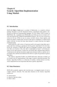
B. Robot Arm The designed arm is basically a 2 DOF planer robotic arm placed on a wooden board. The arm consists of two links made of aluminum sheet, one servo mount, two servo motor and a pen holder as an end effector. A suitable length of arm is maintained so that it can sketch on a A4 size paper sheet . Here end effector is a pen holder attached with a servo motor.
Fig.3. Matlab GUI
Computations, solving systems of linear equations. Matlab has a very large database of built in algorithm for image processing and computer vision applications. It provides many functions for image processing and other tasks. Most of these functions are written in Matlab language and are publicly readable that can be customized. Matlab can write serial data to serial port in different baud rate which are arduino readable. Serial communication between arduino and Matlab is a lot easier than any other system. Because of these advantages we choose Matlab for image processing and inverse kinematics calculation. Due to easy access to the image representing matrix Matlab makes it easy to apply the inverse kinematics to translate the pixel coordinate information to the robot joint angle. There is another fantastic part in Matlab, which is Graphical User Interface (GUI). Graphical User Interface can be designed easily in Matlab. GUI gives an user advantages to interact with the system architecture.
Fig.2(a). Robot drawing image
Fig.3 is our designed Matlab GUI which has been used to give an image as input. GUI has two input feature, acquiring an image by a web cam or from a folder inside computer. D. Arduino Mega Arduino is an open source physical computing platform based on a simple I/O board and a development environment. The Arduino Mega 2560 is a microcontroller board based on the atmega2560. Arduino Mega has been used for servo motor controlling. Arduino receives joint angle information as a serial data. After decoding the joint angle data arduino sends command to the servo how much should it rotate. Fig.2(b). Controller Section
770
E. Servo Motor Servo motor is an actuator that can be controlled precisely for linear or angular position. A servo motor consists of electric motor, feedback device and electronic controller. Servo is needed to feed a signal pulse to rotate for a particular angle. We used MG 996 servo motor which is high torque servo. To use the servo, firstly it needs to be calibrated. For 544us pulse MG 996 servo stays at its zero position and for 2400us that servo stays at 180 degree position.
IV.
A is the desired angle for link 2. The reference line for link 2 to form angle is the line parallel to the link 1. Now we will go for the angle of link 1.
THEORITICAL ANALYSIS
Inverse kinematics is the method for determining the joint angle when the position of the end effectors is known. Tasks to be performed by a manipulator are in Cartesian space whereas actuators work in joint space. The conversion of the position
Now, So, if we know the length of the arm and the position of the end effectors, we will find how much the servo motor should be rotated to reach the end effectors in desired position. Fig.4. Geometry of Inverse Kinematics
and orientation of a manipulator end-effectors from Cartesian space to joint space is called as inverse kinematics problem.
V.
IMAGE PROCESSING AND EDGE DETECTION
Image processing is one of the vital segments of the designed system. The input image is a RGB image which a combination of millions of shed that is too complex to understand for a robot. So we need to convert an RGB image to grayscale where different color combinations are reduced to only black and white intensity. Then grayscale image is converted into a binary image. The process of converting a grayscale image into a binary image is performed by edge detection method. Edges characterize boundaries and are therefore a problem of fundamental importance in image processing. Edge detection significantly reduces the amount of data and filters out useless information.
Let’s establish few expressions to solve the inverse kinematics problem. In Fig.4, link 1 and link 2 forms a triangle with the joining line of the starting point of link 1 and ending point of link 2. So we can apply few equations from the concept of geometry. B is the angle of link 1 and A is the angle of link 2. So, we can write, (1)
Few consecutive steps must be followed to implement the canny edge detection algorithm. The following steps are followed to perform canny edge detection. Firstly smooth the image with a Gaussian filters. Then compute the gradient magnitude and orientation using finite difference approximations for the partial derivatives. Then apply non maxima suppression to the gradient magnitude. Then use the double threshold algorithm to detect and line edges.
(2) (3)
771
The sobel edge detection algorithm use two masks with 3*3 sizes, one estimating the gradient in the x-direction and the other estimating the gradient in the y-direction. The mask is slid over the image, manipulating a square of pixels at a time. The algorithm calculates the gradient of the image intensity at each point and fives the direction to increase the image
black pixel is found that is the beginning of the line and then path drawing algorithm is applied. Path drawing algorithm is a simple algorithm where the system search for the availability of a black pixel around another black pixel and calculate the joint angle from the black pixel coordinate value through inverse kinematics equations and transmit the joint angle
Fig.6. Neighbor Pixel Searching Method
Fig.7. Pixel Searching Precedence
information to the controller to control the servo . Let it be described with the Fig.6. Fig.6 represents a binary image after performing edge detection. There is a single edge consists of black pixels touching one after one makes a chain. The system starts to search from the first pixel if there is a black pixel available and the system finds it in 12 number element of the image containing matrix. Now the system knows that 12 number pixel is the beginning of the edge. Then the system calculate the joint angle from the coordinate value of the 12 number pixel and transmit the joint angle to the controller to reach the end effectors in that coordinate point position. Then it searches around the 12 number pixel i.e. 1, 2, 3, 13, 23, 22, 21, 11. If there is a black pixel available and 13 number element is found as black pixel and transmits it joint angle information to the controller. Again the system searches around the 13th pixel for a black dot and so on till the last black pixel of that line.
Fig.5. Canny and Sobel Edge Detection
intensity at each point from light to dark. Edges areas represent strong intensity contrasts which are darker or brighter. Canny and sobel both are popular edge detection method but their working procedures are different. In Fig.5 we showed binary images after executing Canny and Sobel. VI.
PATH DRAWING ALGORITHM
A binary image is a combination of black and white pixel. When an edge detection method is applied an image is turned into a binary image where few lines or paths indicates the input image. Every line in the binary image contains black pixels attaching one with another. In Matlab a binary image represents a 2D matrix where every element contains the information of the pixel. White pixel represents 1 and black pixel represents 0. The first thing to draw a line is to detect the line from the edges after performing edge detection method. The basic idea is to search the image containing matrix for the black pixel from the first element of the matrix. Whenever a
There is followed a procedure (Fig.7) to search a pixel by its position priority. First, a pixel searches around itself for upper left pixel following by left, lower left, upper, lower upper right, right, lower right.
772
VII. RESULTS AND DISCUSSIONS
•
It is a cost effective, frugality of complexity and user friendly robot. • Graphical User Interface gives user more interaction to control the robot. • Capable of producing higher quality output depending on efficiency of edge detection. Our designed robot has a versatile application in entertainment and educational purpose. It’s a great fun to watch that a robot is sketching image. It’s an inspiration to the general people to know about the robotic activities.
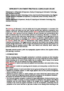
That robotic arm sketched few image of different peoples. After the thorough design of the robot hardware, we obtained a structure that was mechanically strong and got a stable control. Edge detection was performed by Canny and Sobel, In Fig.8 there are few sketches by robot.
Our future research is to develop the drawing quality by increasing the edge detection efficiency. Our target is to modify the current edge detection method to get finest drawing with less possible amount of edges.
IX. [1]
[2]
[3]
[4]
[5]
[6]
[7]
Fig.8. Input Image and Output Image drawn by robot
both of method has it’s own advantages and limitations. Although Canny is an efficient method for edge detection in the sense of keeping the characteristics of input image but it picks a lot of edges which is tedious and time consuming to perform for a robot. On the other hand, Sobel detects less edges that makes robot faster to perform but sometimes it can not represent the input image due to the lack of enough edge. VIII. CONCLUSION In this paper we developed a robotic arm which can sketch human face with a 2 DOF robotic arm. Our research work will motivate the peoples about robots through an interesting behavior of robot. Our designated system has few advantages such as,
773
REFERENCE
Sylvain Calinon, Julien Epiney and Aude Billard, “A Humanoid Robot Drawing Human Portraits”, Ecole Polytechnique F´ed´erale de Lausanne (EPFL), CH-1015 Lausanne, Switzerland Chyi-Yeu Lin, Li-Wen Chuang, Thi Thoa Mac, “Human Portrait Generation System for Robot Arm Drawing”, 2009 IEEE/ASME International Conference on Advanced Intelligent Mechatronics, Singapore, July 14-17, 2009 Yang Junyou, Qiu Guilin, Ma Le, Bai Dianchun, Huang Xu, “Behaviorbased Control of Brush Drawing Robot”, 2011 International Conference on Transportation, Mechanical, and Electrical Engineering (TMEE), Changchun, China, Dec. 2011. A´ kos Ha´mori, Ja´nos Lengyel, Barna Resko, “3DOF drawing robot using LEGO-NXT”, 15th International Conference on Intelligent Engineering Systems, Slovakia, June 2011. Meng Cheng Lau, Jacky Baltes, John Anderson and Stephane Durocher, “A Portrait Drawing Robot Using a Geometric Graph Approach: Furthest Neighbour Theta-Graphs” Shunsuke Kudoh, Koichi Ogawara, Miti Ruchanurucks, Katsushi Ikeuchi, “Painting Robot with Multi-Fingered Hands and Stereo Vision”, 2006 IEEE International Conference on Multisensor Fusion and Integration for Intelligent Systems, Germany, Sept. 2006.