Design and Implementation of Distributed Databases Using Estelle∗ Cléver Ricardo Guareis de Farias 1 Wanderley Lopes de Souza 1 Ciro de Barros Barbosa 2 1
Grupo de Sistemas Distribuídos e Redes (GSDR) Departamento de Computação (DC) Universidade Federal de São Carlos (UFSCar) P.O. Box 676 Via Washington Luiz, Km 235 13565-905 São Carlos (SP) - Brazil e-mail: {clever, desouza}@dc.ufscar.br Tel.: (55)(016)2748232 Fax: (55)(016)2748233 2
Tele-Informatics Group (TIOS) University of Twente PO BOX 217 7500 AE Enschede the Netherlands e-mail:
[email protected]
Abstract Estelle is one of the Formal Description Techniques standardized by ISO that has been successfully used in the development of communication protocols. We believe that the concepts and constructions of Estelle are general enough to be used in other kinds of distributed systems. The main goal of this work is to show how Estelle and a set of appropriate tools can be useful in the development of Distributed Database Systems.
1 Introduction Distributed Systems (DSs) are becoming more and more popular. They have been used to attend the natural distribution of people and information, to provide better performance at lower costs, to facilitate maintenance and to improve the reliability of computer systems. In order to achieve all these objectives DSs have become very complex and today there is no consensus about an exact DS definition. According to Bochmann [1] a DS can be classified having in mind the following types of distribution:
∗
Supported by CNPq, CAPES and FAPESP
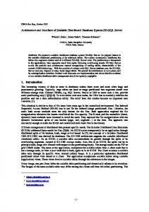
- access, for example, users having access to the services provided by a multi-programming system using terminals at different locations; - computers, for example, a large number of users sharing a set of services provided by a computer network; - processors, for example, a multiprocessor system where the execution of a task is not done by a single processor but it is distributed among several processors; - data, for example, a distributed database system. These types of distribution can be combined, increasing the system complexity, and must be carefully taken into account during the development of a DS. Figure 1 shows the main phases of a Life Cycle of Distributed Systems (LCDS). User’s Requirements Design Validation
Validation
Specification
Conformance Testing Debugging
Tests
Implementation
Prototyping
Figure 1 Life cycle of distributed systems
In the initial phase of this LCDS the user describes what are his needs. In the specification phase the system is designed based on the user's requirements. Frequently many steps are necessary until a final specification of the system can be reached. At each step a more detailed specification of the system is obtained. In the implementation phase an instance of the system specification is produced in a high level programming language (e.g., Pascal, C, C++) using software engineering techniques. The prototyping phase deals with the execution of the implementation in a specific environment using a specific operating system. This phase can be very complex for DSs if the involved processes must run in different machines and must communicate by means of the resources available in the chosen environment. Validation activities can be associated with the phases of this LCDS. The system specification and the system design can be validated. In the design validation the system specification is checked against the user's requirements. The implementation can be tested in order to certify
its conformity with respect to the specification. All these activities can be done formally if the user's requirements and the system specification are formally described. The validation techniques can be classified into two major categories: − verification uses some logical and/or mathematical reasoning to prove some desired properties for the system (e.g., absence of deadlocks, completeness, liveness); − testing and simulation execute an entity (specification or implementation) in order to find errors. In the former the entity is seen as a black box (only the box interfaces can be accessed) while in the latter the entity is seen as a white box (the inner box can also be accessed). This paper concentrates on the specification, implementation, and prototyping phases of the LCDS and uses a simplified distributed database as a development example. Section 2 deals with the subject Formal Description Techniques and presents the specification language employed in this work. Section 3 presents the example, its formal specification and validation while section 4 discusses its implementation and its prototyping. Finally, the conclusions are drawn in section 5.
2 F or ma l D e s c r i pt i on T e c hni que s Distributed Systems may be structured into a set of hierarchical layers [2]. Each layer uses the service provided by the layers beneath it to provide a more powerful service to the next higher layer. A layer service can be modelled by a black box. The service specification is based on the description of the external behaviour of this black box when it interacts with its environment (users) through its interfaces (interaction points). A layer can be obtained by refining the architecture of its service into a set of entities and a lower service provider that abstracts the lower layers. All the components of this new architecture are modelled again by black boxes with interaction points. The layer specification is based on the description of the behaviour of these entities when they interact with their users and with the lower service provider. Service and layer specifications are often done informally or semi-formally. In the first case, a natural language is used; whereas in the second case, a natural language is associated with state tables or state graphs. These kind of specifications are frequently ambiguous and it is difficult to check them for correctness and completeness. The main goal of formal specifications is to produce system descriptions without ambiguities. A formal specification can also be useful in other phases of the system life cycle: some desired properties can be verified, semi-automatic implementations can be generated and the formal specification can be used as a reference for the conformance testing of system implementations. In order to produce formal specifications of distributed systems a Formal Description Technique (FDT) is needed. FDTs are self-contained specification languages, in that the
system specification given in an FDT need not refer to any informal knowledge about this system. A FDT must also have a mathematical basis that can be used to demonstrate the correctness of a specification. Today Extended State Transition Language (Estelle) [3] and Language of Temporal Ordering Specification (LOTOS) [4] are the standard FDTs recognized by the International Organization for Standardization (ISO) and Specification and Description Language (SDL) [5] is the standard FDT recognized by the International Telegraph and Telephone Consultative Committee (CCITT).
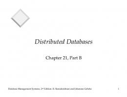
2.1 Extended State Transition Language Estelle development was started in 1981 within the ISO/TC97/SC21/WG1/FDT Subgroup B and this language reached the status of an ISO International Standard (IS) in 1989. Estelle was conceived for the formal specification of distributed systems and communication services and protocols, especially those related to the Open Systems Interconnection (OSI) [2] reference model. Estelle is based on an Extended State Finite Machine model (ESFM) and has a Pascal-like syntax and formally defined operational semantics. Figure 2 shows this model in which the elements (states, interactions and transitions) of a Finite State Machine (FSM) are extended with the constructions (variables, parameters and priorities) of the ISO standard programming language, Pascal [6]. A system architecture is built in Estelle using the module, interaction point and channel constructions associated with the refinement and instance concepts. A hierarchical structure for the system can be constructed refining the modules into submodules. Modules exchange interactions through their interaction points (ip) using bi-directional communication links. A module is a textual definition of a component of the system and module instances are copies of this component.
Estelle = FSM
States Interactions Transitions
+ Pascal
Variables Parameters Priorities
= EFSM
Figure 2 Estelle model A connect link can be established between ips of two module instances that are at the same hierarchical level. An attach link can be established between an ip of an instance of a child module and an ip of the instance of its parent module. All this structure of module instances and communication links can change dynamically. Figure 3 shows an example of an Estelle system architecture. An Estelle specification describes a hierarchically structured system, how this structure is initialized (e.g., Fig. 3 (a)) and how this structure may be changed over execution time (e.g., Fig. 3 (b)). In this example, the initial structure of the Spec specification is composed of the instance A1 of a module A and the instance B1 of a module B. A1 is composed of the
instances SA1 and SA2 of a submodule SA (the module A was refined). The new structure is composed of the initial one and a new instance of the module SA (named SA3) and a new communication link attaching the ip of the instance SA3 to the ip of the parent instance A1. A module is active if it has a behaviour described by a set of transitions, otherwise it is inactive. Active modules must have one of the following attributes: systemprocess or systemactivity if it is a system module; process or activity if it is inside a system module. There are a set of attributing rules that define how modules can be nested and how they can be executed (asynchronous parallelism, synchronous parallelism or non parallelism). The channel construction allows the specification of the interactions to be independent from the module specifications. Its definition is based on the description of the interactions and the roles that must be played by the two ips that will be connected to the edges of this channel. Each interaction can be followed by a parameter list.
Spec
Spec A1
B1 SA2
SA1
A1 SA3
(a) Initial structure
B1 SA2
SA1
(b) New structure attach operation connect operation
Fig. 3 Estelle system architecture A module specification consists of two parts: header and body. The header represents the highest abstraction level of a module and its definition is based on the description of its ips and exported variables. Each ip must be followed by a channel identifier and the role that the ip plays with respect to this channel. An exported variable can be accessed (read/write) by the parent module. The body can have three parts: declarations, initializations and transitions. All the objects to be manipulated (e.g., constants, types, variables, control states, statesets, functions and procedures) and the internal channels and submodules (if there is a refinement) must be defined in the declaration part. In the initialization part the initial control state is assigned to the EFSM associated with the module and the initial values of all additional states are assigned to the corresponding Pascal variables. Static instances of submodules and also static communication links can be created in this part.
The transition part describes the module behaviour. Each transition is composed by conditions and actions. The conditions consist of Estelle clauses while the actions consist of the Estelle clause to, Pascal declarations, Estelle extensions and Pascal restrictions. Dynamic instances of submodules and dynamic communication links can be created/destroyed in this part. Estelle surveys can be found in [7] and [8] and the complete Estelle definition is given in [3].
3 D e s i g n of a S i mpl i fi e d D i s t r i but e d D a t a ba s e S y s t e m A set of users located at different sites must have access to the information distributed over several databases. The system may receive queries of different users at the "same time", however each query should be treated in an independent way. An user query should be followed by a result containing the requested information. The user must wait for this result during a period of time and he can do a new query only if the result arrives or if a timeout occurs. User 2
User 1
...
User m
ip1
ip1
ip1
ip2
ip2
ip2
ip3
Service_Provider
Interface 1
ip3
Interface 2
...
ip3
Interface m
ip4
ip4
ip4
ip5
ip5
ip5
Broadcasting ip6
ip6
ip6
ip7
ip7
ip7
DataBase 1
DataBase 2
...
DataBase n
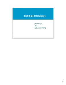
Figure 4 Architecture of the SDDS Estelle Specification These requirements can be mapped into the constructions and concepts of Estelle in order to build an Estelle architecture for this Simplified Distributed Database System (SDDS). The architecture showed in Figure 4 is composed by m instances of the module User and one instance of the module Service_Provider. The module Service_Provider is refined into m instances of the module Interface, one instance of the module Broadcasting, and n instances of the module DataBase. Interface is responsible to individualize the treatment of the queries. An instance of this module is dynamically created when its user starts a query session and it is dynamically released when the user finishes the session. The role of the Broadcasting is to distribute to the DataBase instances a query received from an Interface instance and to return to this Interface the responses received from the DataBase instances.
The skeleton of the SDDS Estelle specification is shown on Figure 5 and the complete specification is presented in [9]. SPECIFICATION SDDS; TIMESCALE SECONDS; CONST ...; { definition } TYPE ...; { Types definition } { Channel Definition } CHANNEL Service_Access(user, service_provider); BY user : start_session; query(p1: type1); finish_session; BY service_provider: result(p2: type2); { Module User } MODULE user SYSTEMPROCESS(user_id: INTEGER); IP ip1: Service_Access(user) INDIVIDUAL QUEUE; END; BODY user_body FOR user; external; { Module Service_provider } MODULE service_provider SYSTEMPROCESS; IP ip2: ARRAY[1..user_number] OF Service_Access(service_provider) INDIVIDUAL QUEUE; END; BODY service_provider_body FOR service_provider; { Internal Channel Definition } CHANNEL Broadcasting_Access(interface, broadcasting); BY interface: query(p3: type1); BY broadcasting: response(p4: type2); CHANNEL DataBase_Access(broadcasting, database); BY broadcasting: query(p5: type3; p6: type1); BY database : response(p7: type3; p8: type2); MODULE interface PROCESS; { Submodule Interface } IP ip3:Service_Access(service_provider) INDIVIDUAL QUEUE; ip4:Broadcasting_Access(interface) INDIVIDUAL QUEUE; EXPORT finish: BOOLEAN; END; BODY interface_body FOR interface; external; MODULE broadcasting PROCESS; { Submodule Broadcasting } IP ip5: ARRAY[1..user_number] OF Broadcasting_Access (broadcasting) COMMON QUEUE; ip6: ARRAY[1..db_number] OF DataBase_Access(broadcasting) COMMON QUEUE; END; BODY broadcasting_body FOR broadcasting; external; MODULE database SYSTEMPROCESS(database: INTEGER); { Submodule DataBase } IP ip7: DataBase_Access(database) INDIVIDUAL QUEUE; END; BODY database_body FOR database; external; MODVAR ...; { Module variable declarations } INITIALIZE ...; { Module variable instance creation } TRANS { 0 - Instance creation of the Submodule Interface } { 1 - Instance release of the Submodule Interface } END; { End of Service_provider Module Specification } MODVAR ...; { Module variable declarations } INITIALIZE ...; { Module variable instance creations } END. { End of SDDS Specification }
Figure 5 Skeleton of the SDDS Estelle specification
3.1 Validation of the SDDS Estelle Development Toolset (EDT) is an environment composed of a compiler (Ec) and a simulator/debugger (Edb). These tools were developed by BULL S.A. based on the functional specification carried out within the Esprit SEDOS Estelle Demonstrator project[10]. Ec translates an Estelle specification into C language source code, and it is composed of the following tools: a translator that returns a Intermediate Form (IF) from an Estelle specification, and a C code generator that takes the IF representation and returns the C-code of the specification. Edb is a symbolic and interactive simulator/debugger and its inputs are the IF and several C-files generated by the Ec. The validation of the SDDS specification was carried out through the analysis of the traces produced during the simulation and, was split into two different phases: a local and a global validation of the specification behaviour. In this sense, the concept of execution cycle is introduced. An execution cycle begins when the user starts a query session and it ends when the user finishes the session. A query session may contain zero or more queries. Considering an execution cycle the local validation must show that a query reaches all the instances of DataBase and that the result of this query reaches the User instance responsible for the query. The traces shown on Figure 6 describe this situation. A trace A(B[I])C(D[I]) should be understood as: B[I], where I is an unique identification number used by Edb to represent a module instance created in the specification, receives an input interaction A and sends to D[I] an output interaction C. ___(USER[7])start_session(SERVICE_PROVIDER[2]) → start_session(SERVICE_PROVIDER[2])___() → ___(USER[7])query(INTERFACE[9]) → query(INTERFACE[9])query(BROADCASTING[3]) → query(BROADCASTING[3]){query(DATABASE[4]),query(DATABASE[5]), query(DATABASE[6])} → query(DATABASE[4])response(BROADCASTING[3]) → query(DATABASE[5])response(BROADCASTING[3]) → query(DATABASE[6])response(BROADCASTING[3]) → response(BROADCASTING[3])response(INTERFACE[9]) → response(BROADCASTING[3])response(INTERFACE[9]) → response(BROADCASTING[3])response(INTERFACE[9]) → response(INTERFACE[9])___() → response(INTERFACE[9])___() → response(INTERFACE[9])result(USER[7]) → result(USER[7])___() → ___(USER[7]) finish_session(INTERFACE[9]) → finish_session(INTERFACE[9])___() → ___(SERVICE_PROVIDER[2])___() →
Figure 6 Local traces of the specification
On the other hand the global validation must show that two or more users are able to make queries at the "same time" and that these queries are treated independently of each other. The
set of traces showed on Figure 7 describes this situation. In this case some traces contain additional information indicating the source interface responsible for the treatment of the query. ___(USER[7])start_session(SERVICE_PROVIDER[2])→ ___(USER[8])start_session(SERVICE_PROVIDER[2]) → start_session(SERVICE_PROVIDER[2])___() → start_session(SERVICE_PROVIDER[2])___() → ___(USER[7])query(INTERFACE[9]) → ___(USER[8])query(INTERFACE[10]) → query(INTERFACE[9])query(9)(BROADCASTING[3]) → query(INTERFACE[10])query(10)(BROADCASTING[3]) → query(9)(BROADCASTING[3]){query(9)(DATABASE[4]),query(9)(DATABASE[5]), query(9)(DATABASE[6])} → query(10)(BROADCASTING[3]){query(10)(DATABASE[4]),query(10)(DATABASE[5]), query(10)(DATABASE[6])} → query(9)(DATABASE[4])response(9)(BROADCASTING[3]) → query(10)(DATABASE[4])response(10)(BROADCASTING[3]) → query(9)(DATABASE[5])response(9)(BROADCASTING[3]) → query(10)(DATABASE[5])response(10)(BROADCASTING[3]) → query(9)(DATABASE[6])response(9)(BROADCASTING[3]) → query(10)(DATABASE[6])response(10)(BROADCASTING[3]) → response(9)(BROADCASTING[3])response(9)(INTERFACE[9]) → response(10)(BROADCASTING[3])response(10)(INTERFACE[10]) → response(9)(BROADCASTING[3])response(9)(INTERFACE[9]) → response(10)(BROADCASTING[3])response(10)(INTERFACE[10]) → response(10)(BROADCASTING[3])response(10)(INTERFACE[10]) → response(9)(BROADCASTING[3])response(9)(INTERFACE[9]) → response(9)(INTERFACE[9])___() → response(10)(INTERFACE[10])___() → response(9)(INTERFACE[9])___() → response(10)(INTERFACE[10])___() → response(9)(INTERFACE[9])result(USER[7]) → response(10)(INTERFACE[10])result(USER[8]) → result(USER[7])___() → result(USER[8])___() → ___(USER[7]) finish_session(INTERFACE[9]) → ___(USER[8]) finish_session(INTERFACE[10]) → finish_session(INTERFACE[9])___() → finish_session(INTERFACE[10])___() → ___(SERVICE_PROVIDER[2])___() → ___(SERVICE_PROVIDER[2])___() →
Figure 7 Global traces of the specification
4 I mpl e me nt a t i on a nd P r ot ot y pi ng of t he S D D S During the last ten years several tools have been built for Estelle. Some of them accept an Estelle specification and generate an implementation kernel in a high level programming language (e.g., Pascal, C, C++). However, a lot of manual coding has to be added to this kernel to produce an executable distributed implementation.
In order to reduce this work, an asynchronous semantic model of Estelle was developed by the National Institute of Standards (NIST). This model can be used as a basis for distributed implementations of Estelle specifications. NIST also developed a set of tools which implement this model: the Portable Estelle Translator (PET) [11] and the Distributed Implementation Generator (DINGO) [12]. The model represents an Estelle specification as a collection of objects, which capture the static features of the specification. An important assumption of the model is that each module is a different operating system process, yielding into inter-process communication to synchronize with other modules. The PET input is an Estelle specification and its output is a representation of the specification in the static model. DINGO takes this representation and generates a set of C++ objects which are classes and variables of the dynamic model. In order to have a system prototype, the generated C++ code must be compiled and linked with run-time libraries and with user libraries to produce a set of executable programs. These programs can run as independent operating system processes on several sites of a distributed system. Figure 8 shows the steps to produce executable code. PET DINGO Representation in Static Model
Estelle Source Files
Representation in Dinamic Model
Executables
C++ Compiler & Linker Run Time Library
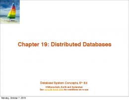
Figure 8 Steps to produce an executable code For each module body defined in a specification, subclasses of an object-oriented library are generated into a set of files. For each instance of this module a process can be created using these files. Figure 9 shows the set of processes generated by PET-DINGO for the SDDS. Each process implements a module instance of the SDDS specification. Figure 10 presents an overview of the C++ code generated for the Controller module. SDDS
Service_Provider
User
Interface
Broadcasting
DataBase
Figure 9 Processes generated by PET & DINGO for SDDS
// Local defs of module _Service_Provider_body /* Frame for Module _Service_Provider_body*/ struct __frame_Service_Provider_body{ _902* Ip2; _910* Ip3; _972* Interface_inst; _776* Broadcasting_inst; _893* Database_inst; }; struct __MI_ Service_Provider_body: _Control { __frame_Service_Provider_body__MIframe; _972 Interface_inst; _776 Sender_inst; __MI_ Service_Provider_body( istream& is) : _Control(is) { } __MI_ Service_Provider_body() : _Control() { } __Interact* __buildInter( int code); char** __locVarNameList(); void __showLocVar( ostream& os, int idx); int __init(); int __selAndExec(int __dt); void __customStart(); }; // definitions for embedded child MI : _Broadcasting_body // definitions for embedded child MI : _Interface_body // definitions for embedded child MI : _Database_body // Implementation file of local defs of module _ Service_Provider_body // Module Broadcasting Instantiation; Broadcasting _inst.pointToMod = new __MI_ Broadcasting_body(); __MI->init(Broadcasting_inst, 0, "_ Broadcasting_body", "_ Broadcasting _body"); int __bound = _DBs_number; I=1; while (Iattach( Ip3[ I], Broadcasting _inst.Ip8()[I]); I++; } // Module Interface Instantiation // Module Database Instantiation // Interaction implementation of the Module Service_Provider _399 inter; __IterList __list; if (__MI->iterate(inter,__list)) do { if (inter.Terminar()) __MI->release( inter); } while (__MI->next(inter,__list));
Figure 10 Overview of the Service_Provider implementation
DINGO not only creates processes, but it also performs the distribution of these processes to one or more sites. When a module instance is created, it is possible to specify where it will run by inserting special comments in the specification. These comments represent the address of a machine where the new process is intended to run. A special file is generated containing a table of records that must be completed with the information about the host name and the path where the executables may be found. In order to perform inter-process communication, DINGO offers the possibility to use either RPC or sockets. However, in both cases server programs must be run on every machine where modules may be started. Figure 11 shows parts of the code responsible for the distribution of the processes generated by DINGO. In this code the functions SPLocation() and UserLocation(), which must be hand written, represent the address where the associated process is intended to run. Inst_control.pointToMod = new _Service_Provider(); __MI->init(Inst_service_provider, “SPLocation()”, "_ Service_Provider_body", "_ Service_Provider_body"); { int __bound = _User_number; I=1; while (Iinit(Inst_user[I], “UserLocation()”, "_User_body", "_User_body"); __MI->connect( Inst_user[I].Ip1(), Inst_service_provider.Ip2()[I]); I++; } }
Figure 11 C++ code responsible for the distribution of the processes
The prototype tests can be done off-line or on-line. In the former case a trace file, containing information about all executed transitions, must be analysed. In the latter case an interface generated by DINGO must be used to monitor the current state of a module instance, to observe the values of exported and local variables, and to observe the links and contents of interactions points. The interface structure is the same for all modules, although it may be extended by hand to satisfy the requirements of each module (e.g., add components to provide data entry).
A
D
SDDS User_1 Interface_1 Service_Provider Server
B
User_2 Interface_2 DataBase_1 Server
User_3 Interface_3 Server
C
DataBase_2 Server
Figure 12 SDDS prototype
An environment composed of several users, and two databases, distributed over a network (Figure 12), was used for the SDDS prototype testing. The testing was done using the trace file and the interface. As in both cases the traces were similar to those obtained by the specification simulation, the prototype was considered validated.
5 Conclusion FDTs are becoming more and more important in the development of distributed systems. They are not restricted to the specification phase, but are being used as the basis for the other phases of the life cycle of these systems. In particular, several tools have been developed for the FDT Estelle, which help in the specification, validation, implementation and testing phases. Neither the simulation nor the testing phases yield conclusive results as so far they restrict the validation activities to pre-defined test scenarios. As such it is not possible to use them exhaustively. However, these techniques can be applied to real systems, which is not always possible with verification techniques. The automatic implementation presents two major advantages: time saving and reliability. The SDDS specification contains 345 lines, while the code generated contains over 4300 lines. Only 440 lines of handwritten code were required to complete the code, i.e., about 90% of the code was automatically generated. Since PET-DINGO was constructed based on the Estelle formal syntax and semantics, it is possible to state that the generated implementation conforms to its specification and it has a high degree of reliability.
6 References [1]
G. v. Bochmann, Concepts for Distributed Systems Design. Springer-Verlag, 1983.
[2]
ISO IS 7498, Information processing systems - Open Systems Interconnection - Basic Reference Model, 1984.
[3]
ISO IS 9074, Information processing systems - Open Systems Interconnection - Estelle A formal description technique based on an extended state transition model, 1989.
[4]
ISO IS 8807, Information processing systems - Open Systems Interconnection - LOTOS - A formal description technique based on the temporal ordering of observational behaviour, 1989.
[5]
CCITT Z100, Functional Specification and Description Language (SDL), 1993.
[6]
ISO IS 7185, Pascal Programming Language, 1983.
[7]
P. Dembinski, S. Budkowski, Specification language Estelle, The Formal Description Technique Estelle (M. Diaz, J.-P. Ansart, J.-P. Courtiat, P. Azema, V. Chari Eds.), North-Holland, pages 35-75, 1989.
[8]
W. Lopes de Souza, Estelle: uma técnica para a descrição formal de serviços e protocolos de comunicação, Journal of the Brazilian Computer Society, NCE/UFRJ Eds., vol. 5, no. 1, pages 33-44, 1989.
[9]
C. B. Barbosa, Modelagem Orientada a Objeto de Especificações Estelle, Master Thesis, PPG-CC/UFSCar, 1995.
[10] BULL S. A. Louvecienes, Edb/Ec User Reference Manual, France, 1992. [11] R. Sijelmassi, B. Strausser, The Portable Estelle Translator: an overview and user guide, Technical Report NCSL/SNA 91/2, NIST, USA, 1991. [12] R. Sijelmassi, B. Strausser, The Distributed Implementation Generator: an overview and user guide, Technical Report NCSL/SNA 91/3, NIST, USA, 1991.