The soft error occurs when the trajectory of one of these particles strikes the storage node of a memory cell. Consider the cell of Fig. 4. When â1â is stored in the ...
Design and Implementation of Error Detection and Correction Circuitry for Multilevel Memory Protection Boris Polianskikh and Zeljko Zilic Department of Electrical and Computer Engineering, McGill University. 3480 University Street, Montreal, Quebec, H3A 2A7 Email: {borisp, zeljko}@macs.ece.mcgill.ca Abstract Traditional memories use only two levels per cell (0/1), which limits their storage capacity to 1 bit per cell. By doubling the cell capacity, we increase density of the memory, at the expense of its reliability. There are several types of memories that employ multilevel techniques. The subject of this paper is the design of Multi-Level Dynamic Random Access Memory (MLDRAM). The problem of their reliability is investigated and a practical solution is proposed. The solution is based on the organization of the Error Correcting Code (ECC), that is tuned to MLDRAM implementation. Conventional memories employ Single-Error-Correcting and DoubleError-Detecting (SEC-DED) ECC. While such codes have been considered for MLDRAM, their use is inefficient, due to likely double-bit errors in a single cell. For this reason we propose induced ECC architecture that uses ECC in such a way that no common error corrupts two bits. Induced ECC allows significant increase in reliability of the MLDRAM, by improved check bit generation circuitry that allows to use less space for parity bit generation circuitry. The suggested approach is able to correct a two bit error in two-bits-per-cell MLDRAM which the basic ECC can not correct. Proposed solutions make MLDRAM more tolerant to any kind of faults and consequently more practical for mass production.
1. Introduction The century of the System-On-Chip (SOC) is approaching quickly. It is often profitable to create few hardware components on a System-On-Chip, and leave many features to be implemented in software. In order to facilitate such a large software component, dense memories are needed. Embedded memory represents perhaps one of the most commonly used components of the SOC, without which the whole SOC will be paralysed. Today’s SOCs characteristics
2. MLDRAM basic operations MLDRAM operation is more complicated than that of the conventional DRAM. The state flow diagram of the cell is shown in Fig. 1. Values show stored binary value and storage voltages in 1.8V technology. Following presented diagram, the read operation first compares stored voltage with reference voltage of 0.9V. Then, depending on obtained result from sense amplifier, the Most Significant Bit (MSB)is assigned to be one (high) or zero (low), where X in the circles stands for unknown value of the Least Significant Bit (LSB). The next operation consists of comparing the stored voltage value with the LSB voltage reference. At the far right side of the diagram,
ELPL PR WRi+1WRi DRe IR _C X C_X ER DRo _SR WLi+1 BL BR
_BL
_BR
Fig. 1: MLDRAM access circuit schematic.
Proceedings of the 32nd IEEE International Symposium on Multiple-Valued Logic (ISMVL’02) 0195-623X/02 $17.00 © 2002 IEEE
RR ZR YSR DBR VDD/2
_DBL
The poor reliability of multilevel memories presents the major obstacle preventing multilevel memory from mass production on the market. All these factors show that modern semiconductor industry is in a state of high demand of well protected, fault-tolerant embedded memories. This paper investigates means to improve the reliability of multilevel DRAMs, while retaining their speed and power performance.
VDD/2
VDD/2
DBL
_SL IL DLoDLeWLi
Shrinking of the technology, as exemplified by Moore’s law, can soon reach its limits. As technology approaches atomic layer dimensions, alternatives should be found to increase the density of stored information by means other than transistor size decrease. Current investigations show that the multi-level approach to storing the information has very good perspectives. Several designs of multilevel memories were actually implemented.
VDD/2
YSLZL RL
include the following: usually there are more than 30 embedded memories, many of them are of different types and sizes, and they are located all over the SOC. Eventually, embedded memories are going to occupy most of the SOC’s area.
_DBR
State 4. All bit lines are precharged to VDD/2, sense amplifiers are turn off. After this memory is in storing state.
the circuitry reads out the value of the cell. MSB reference voltage
LSB reference voltage
11 Write
VDD = 1.8V
1X
1 --- VDD = 0.9V 2
5 --- VDD = 1.5V 6 Noise margins between levels are only 1/3 VDD
HD=1
1
2
Sense MSB
34
5
6 7
Sense LSB
8
Restore
9
PL
10
EL
2 --- VDD = 1.2V 3
PR ER
HD=2
01
WLi
1 --- VDD = 0.6V 3
0X
1 --- VDD = 0.3V 6
HD is a Hamming Distance
DLo HD=1
00
C
VSS = GND
_C _X
Fig. 2: MLDRAM basic operation diagram IR
Fig. 2. shows the circuit schematic, on the basis of which all basic operations are explained. MSB is always accessed from the left side of the circuit and LSB from the right side. There is an interconnect matrix in the middle of the design, which serves for sharing signals between right and left, top and bottom parts of the circuit. The matrix is controlled by signals X, C, _X and _C.
IL ZL ZR RL RR
2.1 Write operation All operations are shown on timing diagram in Fig. 3. Each point represents the state of the memory at a given time. Operation is performed on a cell WLi, which is situated on left complementary bit line. The main difference between operations of the MLDRAM and conventional DRAM is that for read operation, MLDRAM requires different voltage reference generations, depending on the previously read value. The first operation starts from state 1. All operations are explained next. State 1. Control signals YSR and YSL go high and allow data propagate to bit lines. State 2. Control signal IR goes low and disconnects right bit line from sense amplifier, leaving LSB captured on complementary right bit line _BR. Right after this _X goes high and connects _BL and BR, thus allowing both bit lines to carry MSB. Left sense amplifier is disconnected and signal ER pulled up, thus allowing bit lines _BR, _BL, BR to carry total charge.
2.2 Isolate and store operation State 3. Control circuit causes word signal WLi go high and dummy word signal go low. This action captures stored value into the cell.
YSL,YSR Fig. 3: MLDRAM basic operations
2.3 Read operation State 5. At first WLi is enabled, then _C is also enabled. So signal stored in cell is divided between two bit lines _BL and _BR. State 6. Left sense amplifier compares stored value on _BL to BL precharged to VDD/2. Left sense amplifier applies full swing voltage to BL and _BL. Signal IL goes low and latches MSB value on left sense amplifier. State 7. Word line WLi goes high and captures full MSB value (VSS or VDD) in the cell thus creating reference voltage for LSB. Then the left bit lines are precharged to mid voltage and equalized. The MSB cell signal is then distributed onto bit lines _BL, BL, BR by asserting EL and C. The resulting reference signal on BR is then isolated. State 8. The signal IR is assigned and right sense amplifier compares LSB stored value on _BR with reference voltage on BR. Then obtained value is amplified up to full swing voltage and data is ready to be propagated to the data bus. However, read operation is self-destructive (like in conven-
Proceedings of the 32nd IEEE International Symposium on Multiple-Valued Logic (ISMVL’02) 0195-623X/02 $17.00 © 2002 IEEE
tional DRAM) and data needs to be restored. State 9. Restore operation occurs, which is similar to write operation.
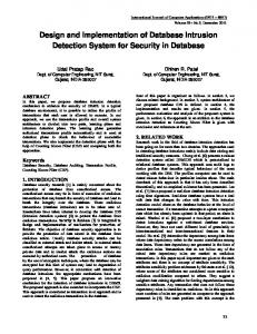
MeV, α-particles can travel up to 10 µm deep into silicon. While doing so, they interact strongly with the crystalline structure, generating roughly 2 x 10⁶ electron-hole pairs in the substrate. The soft error occurs when the trajectory of one of these particles strikes the storage node of a memory cell.
3. Common MLDRAM faults There are two general types of faults affecting MLDRAM. They are known as hard faults and soft faults. The protection scheme has to be applied to both types. Hard faults are permanent and manifested in at least 16 ways [1], as shown in Table [1]. Normally, because of the large areas affected by hard faults, they are better repaired with adding spare memory elements. However, in cases such as cell access transistor stuck open or excessive cell leakage current, when fault affects small number of cells, it is better to repair the damage with ECC. Short between word line and cell capacitor Short between sub-bit line and cell capacitor Short between two cell capacitors No connection between sub-bit line and cell
a-particle WL
n+
VDD
+
1 particle ~ 1 million carriers
+
+
+
-
+
SiO2 -
-
-
Fig. 4: a-particle induces soft error Consider the cell of Fig. 4. When “1” is stored in the cell, the potential well is empty. Electrons and holes generated by a striking particle diffuse through the substrate. Electrons that reach the edge of the depletion region before recombining are swept into the storage node by the electrical field. If enough electrons are collected, the stored value can change [2].
Cell access transistor stuck open Cell access transistor stuck on Excessive cell leakage current Interrupted word line (WLi, WRi) Interrupted sub-bit line (BL, _BL, BR, _BR) Short between adjacent word lines Short between adjacent sub-bit lines Short between word line and sub-bit line Stuck word line (WLi, WRi) Stuck dummy word line (DLo, DLe, DRo, DRe) Stuck bit-line precharge control (PL, PR) Stuck bit-line equalize control (EL, ER) Stuck sense amplifier isolation control (IL, IR) Stuck sense amplifier precharge control (ZL, ZR) Stuck switch matrix signal (C, _C, X, _X) TABLE 1. Hard faults in MLDRAM The second type of fault is a soft fault. Due to reduced noise margins (600 mV for 0.18 µm technology) MLDRAM becomes very susceptible to soft errors. Mostly soft errors occur because of the α-particles, that are He2+ nuclei (two protons, two neutrons) emitted from radioactive elements during decay. Traces of such elements are unavoidably present in the device packaging materials. With emitted energy of 8 to 9
4. Induced ECC code for MLDRAM Conventional ECC for 1bit/cell memory, that is also used for MLDRAM described in [3], [4]. Unfortunately, this architecture of the ECC is not efficient for the MLDRAM. The noise margin between levels of storage 01 and 10 is only 1/3 of VDD. This fact creates high probability of errors with Hamming distance 2 (difference between two binary words). Another drawback is that this ECC has to wait for both MSB and LSB to be ready for processing through ECC. The proposed ECC, shown in Fig. 5, is able to avoid and solve problems that occur using conventional ECC. Based on a fact that ECC is able to interact with the memory and affect its operations, this ECC is called induced. Induced ECC exploits an idea that MSB and LSB are read out at different time and that LSB value strongly depends on previously read MSB value. The operation of the induced ECC is quite simple. During the write operation, data is divided in two groups: MSB group and LSB group. Since MSB and LSB can be written at the same time, they are processed through different check bit generators. This also can be done by using only one check bit generator, but in this case, the time to generate check bits will double.
Proceedings of the 32nd IEEE International Symposium on Multiple-Valued Logic (ISMVL’02) 0195-623X/02 $17.00 © 2002 IEEE
MSB k/2 bits
Input data k bits
LSB k/2 bits
k
c1
c2
c3
0 k
Check Bit Generator z bits
Check Bit Generator z bits Check bits
Double error alarm
Corrected data
MEMORY CORE Check Bit Generator z bits
Z
Z
Syndrome Generator z bits
Uncorrected data
Decoder
CORRECTION Corrected data OUTPUT
LATCHES Output data k bits
Fig. 5: Induced ECC for 2-bit/cell memory
Check bits are generated according to Table [2]. The table is constructed in such a way that the effect of each erroneous bit is unique; a unique combination of parity check bits is produced in each individual case, so the erroneous bit can be easily located. Also one total parity check bit has to be generated in order to detect a double bit error. Check bits are stored in two separate locations, z bits for MSB and z bits for LSB. The most left column of the table shows all 16 bits of the bus plus check bits c1 to c5. The right most column represents positions of the erroneous bit for row decoder. For example, if bit 2 is affected, the row number 6 will be excited since the unique combination of check bits c3 and c4 is responsible for bit 2. It should be noted that bit c5 represents less significant bit and c1 represents most significant bit as it may be seen at the bottom of Table [2]. Comparing check bits c1 and c2 in Table [2], one can see that the check bit c2 can serve as a parity generator for bits 4 to 10, inclusively, and check bit c1 as a parity generator for bits 11 to 15. This fact was exploited for total parity generator bit c6.
c4
c5
c4
c5
3
c5
5
1
c3
2
c3
c4
3
c3
c4
4
c2
5
c2
c4
6
c2
c4
7
c2
c3
8
c2
c3
9
c2
c3
c4
10
c2
c3
c4
c5
7
c5
9 10
c5 c5
c1
12
c1
c4
13
c1
c4
14
c1
c3
15
c1
c3
c1
c1
13 14
c5
15
c5
17 18
c5
19 20
c5
21 16
c2
c3
8 c3
c4
4 c4
c5
2 c5
24
11 12
11
c2
6
23
22
21
1
20
Table 2: Check bits generation for induced ECC (k=32). 5. Efficient total parity check As seen from Table [2] check bit c1 serves as a parity generator for bits 11, 12, 13, 14, 15 and check bit c2 serves as a parity generator for bits 4, 5, 6, 7, 8, 9, 10. Since check bits c1 and c2 are used as parity generators for completely different bits we understood that it was possible to reuse them for total parity generator bit c6. As shown in Fig. 6, total parity check bit was constructed using check bits c1, c2 and 5 additional XOR gates, instead of using additional 15 XOR gates for total parity generation, which significantly reduces area occupied by induced ECC. Check bit generators take k/2 bit on the input and encode z bits on the output, where z satisfies bounds in Equation (1)
Proceedings of the 32nd IEEE International Symposium on Multiple-Valued Logic (ISMVL’02) 0195-623X/02 $17.00 © 2002 IEEE
z k 2 ≥ z + --- + 1 2
(1)
During the read operation, the bits that were generated during the write operation (c1w, c2w, c3w, c4w, c5w) are compared with newly generated bits (c1r, c2r, c3r, c4r, c5r) through syndrome circuitry, as shown in Fig. 5. There are three possible outcomes that can happen during the comparison.
c6 c5
c4
c3
c2
c1
0 1 2 3 4 5 6 7 8 9 10 11 12 13 14 15 Fig. 6: Improved check bit generator for induced ECC A) the first case, there are neither single errors nor double errors. In this case, the binary syndrome S1 through S5 returns “zero” and the output of total parity bits c6w and c6r do not differ, which returns zero on the output of the XOR gate for c6 comparison. A “zero” from total parity check bit c6 propagates through inverter, and there are “zero” and “one” at the inputs of AND gate, which gives a negative result for the double bit error detection alarm. B) the second case, there is a single error and no double errors. In this case, the binary syndrome S1 through S5 gives some binary value other than “zero” showing the exact location of the error. The total parity bits c6w and c6r also differ, which returns “one” on the output of XOR gate for c6 comparison. “One” from total parity check bit c6 propagates through inverter and there are “zero” and “one” at the inputs of AND gate, which again gives a negative result for the double bit error detection alarm. C) the third case, there is a double bit error. In this case, the binary syndrome S1 through S5 gives some binary value other than “zero” showing the location of the error, but the location is erroneous itself and should not be used for correction. At the same time, bits c6w and c6r do not differ, which returns “zero” on the output of XOR gate for c6 comparison. “Zero” from total parity check bit c6 propagates through an inverter
and there are “one” and “one” at the inputs of AND gate, which now gives a positive result for double bit error detection alarm. This situation produces double bit error alarm. If there are more than two erroneous bits, this circuitry fails to work properly. After the comparison, the data has to propagate to the decoder and correction circuitry. The decoder and correction circuitry were implemented as a single block, shown in Fig. 7. The decoder is implemented on a basis of a standard NOR decoder with improved enable signal. All uncorrected data from a memory location propagates to the inputs of XOR gates and is compared to the same data that propagated through ECC circuitry. The operation of the decoder and correction circuitry is best demonstrated on an example. Assume that the bit 7 originally was “0”, and after read operation it was read as “1”. In this case, as it is shown in Table [2], only check bits c2 and c3 will differ after read operation. This combination corresponds to binary value 12 as it is seen from right part of Table [2]. Syndrome bits S1 through S5 will propagate to decoder. As soon as the decoder is enabled with negative signal, only the row that goes to the same XOR gate as bit 7 will be pulled up “high”. Since corrupted value is “1” and exited row produces “1”, the XORed output (bit7out) will give a corrected value “0”. The same is true for the opposite corruption polarity. Assume that the bit 7 originally was “1” and got corrupted to “0”. The same row will be exited and corrupted “0” XORed with exited row will give “1”. An additional feature that improves the decoder function is the enable signal. NMOS and PMOS transistors in the left part of the Fig. 7 serve for precharging and discharging the row lines. In order to precharge one of the decoder lines, enable has to become “low”. In this case, all PMOS transistors in the left part will be turned on, but only one binary chosen row line will be pulled up since the rest of the lines will be discharged by NMOS transistors in the right part of the circuitry. However, if at certain moment the decoder has to be disabled, the enable signal has to become “high”. In this case, the enable signal is pulled up and NMOS transistors at the left part of the circuitry are turned on. As soon as NMOS transistors are turned on, all row lines become discharged and the decoder does not make any changes to the correction circuitry. The addition of the extra NMOS transistors in the left part of the decoder prevents ECC from erroneous correction and saves power consumption, since we do not need to apply additional signals on S1through S5 in order to discharge all row lines. As shown in Fig. 3, an MSB is generated first and is ready at state 7. At this point, all MSBs can be processed through check bit generator and compared with MSBs that are stored in the memory. After processing MSBs through the rest of the
Proceedings of the 32nd IEEE International Symposium on Multiple-Valued Logic (ISMVL’02) 0195-623X/02 $17.00 © 2002 IEEE
ECC, there are three possible outcomes available. • First outcome: there is a single bit error amongst MSBs. ECC is able to correct it and returns correct values back to memory. By doing so, we avoid a double error, since the wrong MSB value will be automatically written back to the cell (state 7 of Fig. 3). Also, the memory is protected against the error between levels 01 and 10 (Hamming distance two).
• Third outcome: there are no errors between MSBs. MSB values are latched to output latches and ECC is ready for LSB checking. Now, LSB check bits are propagated through the same blocks as MSB. Depending on the outcome of the correction circuitry, data is either latched to output latches and ready to be read or ECC sends double bit error signal to the processor and memory waits for further instructions.
6. Performance of the induced ECC
VDD!
c1
VDD! VDD! VDD!
c2 c3
VDD!
c4 c5
VDD! VDD!
bit15out bit14out
VDD! VDD!
bit13out bit12out
VDD! VDD!
bit11out bit10out
VDD! VDD!
bit9out bit8out
VDD! VDD!
bit7out
The reliability model was derived and all modelling was performed using MATLAB. The model is combinatorial, which means that the set of the operational states of the system is categorized in such a way that the probabilities of each of the states can be determined by combinatorial means [4]. As shown in Fig. 8, the MLDRAM can be described as a state flow diagram with all possible states it can tolerate. Curved lines show normal transitions and straight lines show faulty transitions that can happen due to several reasons. Fig. 8 (a) shows that MLDRAM protected with conventional ECC can not tolerate faulty transitions with Hamming distance 2. Fig. 8 (b) shows that MLDRAM protected with induced ECC can tolerate any faulty transition between the states. Equation (2) describes reliability R(γ) of the previously described system.
bit6out
VDD! VDD!
bit5out
f
VDD! VDD!
bit3out
i
bit2out VDD!
bit1out bit0out
VDD! VDD! VDD! VDD! VDD!
c1r-c5r bits 0 through 15 obtained during _Enable S1 S2 S3 S4 S5 the read operation Fig. 7: The decoder and the correction circuitry schematic
• Second outcome: there is a double bit error. ECC is not able to correct it, but it returns the double bit error detection alarm to the memory controller. Since the double bit error between MSB will provoke double error between LSB, it does not make any sense to continue the read operation and upon receiving MSB, a double error alarm signal memory controller stops the read operation at state 7. As it can be seen from Fig. 3, by doing so we save time and power consumption. Simulations show that time saved is about 35 ns for 0.18 µm technology.
∑
R(γ ) =
bit4out
VDD!
=1
F ( 1 – α ) i α( F – i ) i
(2)
where F is a total number of faulty transition that can happen in the system. From Fig. 8 follows that there are 6 faulty transitions which can happen in MLDRAM; f is the number of faulty states that system can tolerate. From Fig. 8 follows that MLDRAM protected with conventional ECC can tolerate only up to 4 faulty transitions (f=4) and MLDRAM protected with induced ECC can tolerate up-to 6 faulty transitions (f=6). α is the probability of the possible faulty transition. α itself is a function of the cell area Acell and of the, so called, γ factor and is expressed by Equation (3). Actually, for MLDRAM γ is the main factor that affects MLDRAM system reliability, which itself depends on many factors, such as noise margins of the system, defect density and so on.
α = e
– ( A cell ⋅ γ )
(3)
Equation (2) is graphically shown in Fig. 9. The induced ECC code significantly improves reliability of the MLDRAM comparing to the conventional ECC code. It has to be mentioned that the plot for MLDRAM without ECC was obtained as a system that can not tolerate any faulty transitions.
Proceedings of the 32nd IEEE International Symposium on Multiple-Valued Logic (ISMVL’02) 0195-623X/02 $17.00 © 2002 IEEE
10
01
10
00
11
00
11
(a)
(b)
Fig. 8: State flow diagram for MLDRAM (a) MLDRAM protected with conventional ECC (b) MLDRAM protected with induced ECC
Reliability
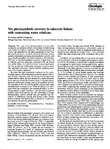
By designing induced ECC, one has to cope with area and delay propagation that eventually affects the overall memory performance. Bus width dramatically affects area occupied by check bits. It is more profitable to have wide buses than narrow ones. For example, for 2 bit wide bus we need 4 check bits, which makes it 200% of the area occupied by redundancy bits; for 16 bit wide bus we need already 50% redundancy and so on. At the same time, one should deal with propagation delay introduced by ECC in the whole circuitry. As shown in Fig. 10, the propagation delay time dramatically increases with increasing the number of information bits. For example, just increasing the bus from 4 bits to 100 bits introduces as much as almost 7 times more delay into the circuitry. It is obvious that bus width introduces completely opposite effects on the redundancy percentage and propagation delay. For redundancy percentage it is better to have a larger bus. Meanwhile, for propagation delay it is better to have the bus width as small as possible.
Propagation delay time, ns
01
Bus width or number of information bits
Fig. 10: Propagation delay as a function of a bus width
7. Conclusions The conventional ECC can not cope with some of the most common errors in MLDRAM, as they appear to corrupt two bits. The induced ECC scheme improves correction of these errors, and hence increases the MLDRAM reliability. An implementation of induced ECC circuitry that is tightly coupled to MLDRAM sensing circuitry is presented and its performance is shown to surpass that of the conventional ECC. References [1] M.Redecker, B. F. Cockburn and D. G. Elliot, “Fault-models and tests for a 2-bit-per-cell MLDRAM”, IEEE Design & Test of Computers 1999, pp. 22-31. [2] J. M. Rabaey “Digital Integrated Circuits, a Design Perspective”, Prentice Hall, upper Saddle River, New Jersey 07458. [3] C.Wickman, A.Chan, T. Brandon, Y. Xiang, J. Koob, P. Bartosec, B. Cockburn and D. Elliot “Semiconductor File Memory” Micronet Annual Workshop, Ottawa 2001, pp-23-24.
MLDRAM with induced ECC
[4] B. W. Johnson, “Design and Analysis of Fault-Tolerant Digital Systems.” Addison-Wesley, 1957.
MLDRAM with conventional ECC
[5] P. Gillingham, “A Sense and Restore Technique for Multilevel DRAM”, IEEE Trans. Circuits and Systems-II: Analog and Digital Signal Processing, vol. 43, no. 7, pp. 483-486, July 1996. [6] T. Furuyama et al., “An Experimental 2-bit/Cell Storage DRAM for Macrocell or Memory-on-Logic Application”, IEEE J. SolidState Circuits, Vol. 24, No. 2, pp. 388-393, April 1989.
MLDRAM without ECC
[7] T. Okuda et al., “A Four-Level Storage 4-Gb DRAM”, IEEE J. Solid-State Circuits, Vol. 32, No. 11, pp.816-823, July 1993. Time in hours X 5000
Fig. 9: Reliability induced ECC
improvement
with
Eventually designer has to choose optimal trade-off that suits best to his needs, either it is space saving strategy or increasing of the speed strategy.
Proceedings of the 32nd IEEE International Symposium on Multiple-Valued Logic (ISMVL’02) 0195-623X/02 $17.00 © 2002 IEEE