Indian Journal of Science and Technology, Vol 10(29), DOI: 10.17485/ijst/2017/v10i29/117368, August 2017
ISSN (Print) : 0974-6846 ISSN (Online) : 0974-5645
Design and Implementation of PLC based Automatic Liquid Distillation System Muhammad Farrukh1*, Irfan Ahmed Halepoto2, Bhawani Shankar Chowdhry2, Hameedullah Kazi1 and Bharat Lal1 Department of Electrical Engineering, ISRA University, Hyderabad, Pakistan;
[email protected] 2 Department of Electronics Engineering, Mehran UET, Jamshoro, Pakistan
1
Abstract Objectives: This paper proposes the design and implementation of an automatic liquid distillation system. The prototype is designed for mainly two functions: liquid distillation and tank level. Methods/Statistical Analysis: Prototype presented involves a process of separating the mixture (Methanol & water) and improves the production by managing the whole system automatically. The prototype designed gives a simple controlling & monitoring i.e. data acquisition of fluid level with the help of PLC S7200. Distillation is the main theme behind this research work that plays a vital role in many industries in dealing with boiling of liquids and liquid levels. Findings: At initial stage the implementation of a robust mechanical design is constructed to sustain excessive temperature; besides this a console panel is made to manually control and indicate the state of actuators. At final stage PLC interfacing and programming with electrical components (level detector circuit, thermocouple, pump, heater, solenoid valve etc.) is done for achieving the efficient and fast automatic process. In the last design was experimented with actual solution, it was found that 90% of the methanol was retrieved in condensation chamber; also temperature linearization was observed during the process. Applications: Error free mechanism and fast actuation makes this model significant for many industries which deal with huge boilers where engineers tackle with controlling & monitoring of liquids i.e. sugar mills, milk factories etc.
Keywords: Analog Module EM235, Liquid Distillation, PLC S7200, STEP 7 Micro-Win, Tank Level Controlling
1. Introduction Nowadays, automatic-control instrumentation plays a vital role in any industrial system or plant.1 Control engineers usually deals with crucial processes at industries in developing, installing and maintaining the equipment to make sure that the system operation and processes involves smartness and safely. When it comes to instrumentation and automation, Programmable Logic Controllers (PLCs) are the solid control system that continuously monitors the status of devices connected to the inputs.2 PLC is a controller with functions to perform timing, counting, arithmetic manipulations, control logic and sequencing. Basically, PLCs are very much similar to an industrial computer that has a built-in memory, I/O interfaces, Central Processing Unit (CPU) and a pro*Author for correspondence
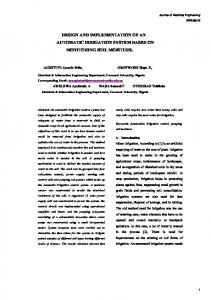
gramming device.3 Central Processing Unit (CPU) of a PLC consists of microprocessor, memory chip and control logic circuitry for communication and monitoring. CPU can be operated in programming mode to download logic from device and in run mode to execute the program and start the process. PLCs usually support five programming languages i.e. Ladder diagram programming (LD), Sequential Function Charts (SFC), Structured Text (ST) Instruction List (IL) and Functional Block Diagram (FBD). Through I/O interfaces, the logic controller can sense and estimate the physical quantities concerning a process, such as motion, level, temperature, pressure, proximity, position etc.4 The programs written on a PC are downloaded into the non-volatile flash memory of PLC via a Point to Point Interface (PPI) cable.5 The basic structure of PLC is shown in Figure 1. The experimen-
Design and Implementation of PLC based Automatic Liquid Distillation System
Figure 1. Basic Structure of PLC.
tal process is based on PLC S7-200 (CPU 224) belongs to Siemens SIMANTIC Family. The compatible software used with S7200 is STEP 7 Micro-Win; which supports Ladder Diagram programming (LD), Instruction List (IL) and Functional Block Diagram (FBD).6 Distillation is a process of splitting the substances from a liquid compound mixture by appropriate evaporation and condensation.7 The process is used commercially for many processes for instance: production of alcohol, xylene, distilled water, gasoline and many other liquids. Simple distillation is used for separation of methanolwater mixture.8 To implement the process of automatic distillation PLC S7200 is robust choice.9 It provides the efficient data acquisition, continuous controlling and monitoring of physical quantities. This research work focuses on a safe and user friendly electronic system that can perform distillation with maximum productivity involving less human intervention. The rest of paper proceeds as follows: Section 1 discusses the basics of PLC system; an experimental setup is carried out for liquid distillation & tank level based on PLC S7-200 in Section 2. Section 3 describes the working and the designed hardware tank level detector, interfacing of sensors & actuators with PLC is discussed in Section 4. In Section 5 ladder diagram programming is developed and logic is controlled by PLC S7-200 with STEP 7 micro-win software, experimental results and analysis are carried in Section 6. Finally paper is concluded in Section 7.
2. Experimental Setup The experimental system is based on two scenarios i.e. tank level and automatic distillation. The block dia-
2
Vol 10 (29) | August 2017 | www.indjst.org
gram of this experimental setup is shown in Figure 2. To separate methanol-water liquid mixture by distillation process, we first heat them in a distillation unit. The substance with less boiling point (Methanol) will typically evaporate first and the vapors will pass into a condensing column, where it can revert into a liquid (condense) on the cool flask. It must be noted that boiling point of water H2O= 1000C & methanol CH3OH= 64.70C. The experimental setup starts with empty tank, so level circuit sends high signal to the PLC S7-200 CPU 224. The PLC activates the actuator motor pump, which pumps the solution and fills it in the tank. As the tank becomes full, the PLC stops the motor pump and this process is continuously repeated. After cutting off the pump; level circuit also drives the heater with delay of 5 seconds. At the low signal of the level circuit, the PLC starts heater to raise the temperature of the tank. The heater is kept on until the temperature of the tank is reached at 700C. At this temperature level, the methanol is vaporized completely from the solution and only water solvent is left behind. The temperature is sensed by the temperature sensor, a thermocouple (J-type) is used which is interfaced to the PLC though signal conditioning circuit and its readings are monitored continuously and accordingly an action is performed by the PLC. The vaporized solution creates a path from where the vapors pass through the condenser. The condenser changes the gas state back into the liquid state. As condenser is filled with cold water, the separated liquid is then collected into the separate Flask. Finally, the water remained in the distillation unit is drained into the lower tank through solenoid valve. Based on the connectivity as shown above, distillation unit of the system is proposed as shown in Figure 3.
Indian Journal of Science and Technology
Muhammad Farrukh, Irfan Ahmed Halepoto, Bhawani Shankar Chowdhry, Hameedullah Kazi and Bharat Lal
placed in the bottom. The probes A, B, C, D, E & F are set as 0% (Empty), 20%, 40%, 60%, 80% & 100% (Full) level respectively. Level circuit works on a mechanism that whenever probe S and A are in contact a minor current is drawn from S to A through the base of transistor Q1 and water via 2.2KΩ resistor. As a result the transistor comes to a saturation state causing the LED6 (D6) to glow.
Figure 2. Block Diagram of PLC Based Automatic Liquid Distillation System.
Figure 3. Distillation Unit and Tank Level.
3. Tank Level Detector Circuit The level circuit used in this circuit is point type i.e. it will show the level in discrete six points. It is a transistor based circuit which is used as a switch as shown in Figure 4. Probe S works as a common to other six wires. Accordingly, the wire S is used as a reference level and
4. Interfacing of Sensors and Actuators with PLC The sensor used in this research work is Thermocouple (J type) whereas actuators are pump, heater and solenoid valve. Thermocouple (J type 50uV/C) is employed to sense & maintain the temperature to convert the methanol into vapors at its boiling point (64.70C). To operate it efficiently signal conditioning IC (4558 op-amp) is used so that the signal can be detected by PLC analog input in EM235 module with PLC input address AWI0. The Thermocouple Conditioning Circuit (AIW0) is shown in Figure 5. The pump used in this project is a submersible pump having ratings of 10W (power) 700L/H. It needs 220V 50Hz. The PLC S7200 gives the output of 24volts & 3amps so to trigger a pump we have at desired event used relay. Here the pump is connected to normally closed & is operated as active low having PLC o/p address Q2.0 as shown in Figure 6. Likewise, heater also needs 220V 50Hz for proper operation. Heater is connected to normally open and operated as active high with PLC o/p Address Q2.1 as shown in Figure 7. Similarly, the Solenoid valve need only
Figure 4. Tank Level Detector Circuit.
Vol 10 (29) | August 2017 | www.indjst.org
Indian Journal of Science and Technology
3
Design and Implementation of PLC based Automatic Liquid Distillation System
Figure 5. Thermocouple Conditioning Circuit (AIW0).
12V for operating as an active high actuator having PLC o/p address Q2.2 as shown in Figure 8.
Figure 8. Solenoid Circuit (Q2.2). Figure 6. Pump Circuit (Q2.0).
Figure 7. Heater Circuit (Q2.1).
4
Vol 10 (29) | August 2017 | www.indjst.org
Figure 9. Ladder diagram of Step 7 Micro-Win Environments.
Indian Journal of Science and Technology
Muhammad Farrukh, Irfan Ahmed Halepoto, Bhawani Shankar Chowdhry, Hameedullah Kazi and Bharat Lal
5. STEP 7 Micro-Win Programming In this work, the automatic distillation system is controlled by PLC S7200 having compatible software STEP 7 Micro-Win to program accordingly. Ladder program is used as a smart language to program any industrial application. Figure 9 shown below denotes the flow chart and Figure 10 shows the programming strategy in Step and Micro-win.
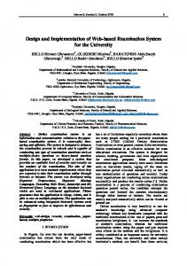
that 90% of the methanol was recovered from the mixture as the distillation unit was heated and maintained up to 700C for almost 30 mints. The separated methanol was condensed in the condensation chamber. Table 1. Mixture of Methanol-Water in Time V/S Temperature Sl.NO
Time (mins)
Temperature 0C
1.
4.4
35
2.
8.1
40
3.
12.4
45
4.
16.5
50
5.
20.5
55
6.
24.8
60
7.
29.1
65
8.
33.2
70
Figure 10. Automatic Distillation System Flow Chart.
6. Experimental Results and Analysis
Figure 12. Thermocouple Lineariztion Results of Time V/S Temperature.
The proposed system implementation is shown in Figure 11 and is experimented with a mixture of MethanolWater. During observation a linearization was found between the time and temperature as shown in Table 1 and graph plotted as shown in Figure 12. It must be noted
7. Conclusion The proposed research successfully presented automatic electronic distillation system which can perform the process with error free mechanism. On the other hand
Figure 11. System Implementation of Methanol-Water Mixture. Vol 10 (29) | August 2017 | www.indjst.org
Indian Journal of Science and Technology
5
Design and Implementation of PLC based Automatic Liquid Distillation System
approach employed gave a smart and efficient idea to separate the methanol and water from the mixture. Design being simple, economic and affordable can be implemented in any concerned industry for the presented tasks. Lastly, the system designed improved productivity of the methanol in the condensation chamber. When it is concerned to future work a HMI interface can also be implemented. The whole process can be controlled and monitored graphically. HMI software’s like WinCC, LABVIEW and KINGVIEW can be employed with PLC S7200. Besides we can also deploy a GSM modem (TC35 & SIM900) enabling the site engineers to get the status of the process with span of few seconds anywhere anytime.
8. Acknowledgments The authors of this research would like to thank Department of Electronics Engineering, Mehran UET, Jamshoro, Pakistan and Department of Electrical Engineering, ISRA University, Hyderabad, Pakistan for their technical support in providing us Instrumentation & Control Laboratory.
9. References 1. Halepoto IA, Khaskheli S. Modeling of an Integrated Energy Efficient Conveyor System Model using Belt Loading Dynamics. Indian Journal of Science and Technology. 2016; 47(9). Crossref
6
Vol 10 (29) | August 2017 | www.indjst.org
2. Baladhandabany D, Gowtham S, Kowsikkumar T, Gomathi P, Vijayasalini P. PLC based automatic liquid filling system. International Journal of Computer Science and Mobile Computing. 2015; 4(3):684–92. 3. Yu H. The Design and Realization of PID Liquid Level Control System Based on S7-200 and EM235. IEEE International Conference on Intelligent Computation Technology and Automation (ICICTA); 2010. p. 762–5. Crossref 4. Memon TR, Halepoto IA, Memon TD. Embedded DAQ System Design for Temperature and Humidity Measurement. Mehran University Research Journal of Engineering & Technology. 2013; 32 (2):253–60. 5. Panchal P, Patel A, Barve J. PI control of level control system using PLC and Lab VIEW based SCADA. In IEEE International Conference on Industrial Instrumentation and Control (ICIC); 2015. p. 1196–201. 6. Han M, Clough DE. Nonlinear model based control of twoproduct reactive distillation column. Korean Journal of Chemical Engineering. 2006; 23(4):540–6. Crossref 7. Sreejeth M, Chouhan S. PLC based automated liquid mixing and bottle filling system. IEEE International Conference on Power Electronics Intelligent Control and Energy Systems (ICPEICES); 2016 Jul. p. 1–5. Crossref 8. Ansari S, Soomro AA, Kalwar IH, Solangi US, Noonari AS. PLC based Automatic Distillation and Collection of Ethanol-Water Solution. Indian Journal of Science and Technology. 2016; 47(9). Crossref 9. Siemens SIMATIC S7-200 PLC. Available from: http:// www.automation.siemens.com
Indian Journal of Science and Technology