Design and manufacturing interface modelling for manufacturing processes selection and knowledge synthesis in design Achraf Skander, Lionel Roucoules, Jean-S´ebastien Klein Meyer
To cite this version: Achraf Skander, Lionel Roucoules, Jean-S´ebastien Klein Meyer. Design and manufacturing interface modelling for manufacturing processes selection and knowledge synthesis in design. The International Journal of Advanced Manufacturing Technology, 2008, 37 (5-6), pp.443-454. .
HAL Id: hal-00940085 https://hal.archives-ouvertes.fr/hal-00940085 Submitted on 31 Jan 2014
HAL is a multi-disciplinary open access archive for the deposit and dissemination of scientific research documents, whether they are published or not. The documents may come from teaching and research institutions in France or abroad, or from public or private research centers.
L’archive ouverte pluridisciplinaire HAL, est destin´ee au d´epˆot et `a la diffusion de documents scientifiques de niveau recherche, publi´es ou non, ´emanant des ´etablissements d’enseignement et de recherche fran¸cais ou ´etrangers, des laboratoires publics ou priv´es.
Science Arts & Métiers (SAM) is an open access repository that collects the work of Arts et Métiers ParisTech researchers and makes it freely available over the web where possible.
This is an author-deposited version published in: http://sam.ensam.eu Handle ID: .http://hdl.handle.net/10985/7736
To cite this version : Achraf SKANDER, Lionel ROUCOULES, Jean-Sébastien KLEIN MEYER - Design and manufacturing interface modelling for manufacturing processes selection and knowledge synthesis in design - The International Journal of Advanced Manufacturing Technology - Vol. 37, n°5-6, p.443-454 - 2008
Any correspondence concerning this service should be sent to the repository Administrator :
[email protected]
Design and manufacturing interface modelling for manufacturing processes selection and knowledge synthesis in design Achraf Skander & Lionel Roucoules & Jean Sébastien Klein Meyer
Abstract The research results presented in this paper are related to the specification of a method and models that tackle the problem of manufacturing processes selection and the integration, as soon as possible, of their constraints in the product modelling (i.e. information synthesis). This method is based on a skin and skeleton design/manufacturing interface model that ensures connection between design and manufacturing information. The use of these features is justified by their capacity to make a product representation which allows integration of both design and manufacture data and therefore assists the product breakdown definition (including the 3D forms) by least commitment. This method first analyses the product data issued from functional analysis and component selection (form, roughness, tolerance interval, etc.). Then, it deals with manufacturing information (manufacturing processes constraints). The approach is formalised with IDEF and UML models and has been consolidated with software developments based on C++ and open CASCADE technologies. Keywords Concurrent engineering . Design and manufacture interface . Feature-based product modelling . DFM . Knowledge synthesis . Skins and skeleton concepts . Manufacturing knowledge management
A. Skander : L. Roucoules (*) : J. S. Klein Meyer Charles Delaunay Institute - FRE 2848, Laboratory of Mechanical Systems and Concurrent Engineering (LASMIS), University of Technology of Troyes, BP 2060, 12 rue Marie Curie, 10010 Troyes, France e-mail:
[email protected]
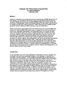
1 Introduction In a context of deep change of industrial market related to globalisation and delocalisation, being competitive becomes a challenge for all industries. In order to increase product quality and reduce production cost, the right information must be provided at the right time to the right person. DFX (design for X) methods provide approaches that take into account a maximum of product life cycle information during the design process. A design solution is then the result of multiple expert product assessments and a collaborative multidisciplinary decision making process. The authors’ research activity is based on a framework to support manufacturing information synthesis in design. That research work is included within a general context of concurrent engineering (CE) and integrated design. Figure 1 presents the global concept of the framework in which each design expert involved in the design project can access a central information kernel where information is shared. Product information is therefore first managed individually in asynchronous mode by each member of the design group and then shared in asynchronous or synchronous mode for collaborative activities. A manufacturing processes selection activity is specifically studied by the authors here. The most important result of the paper is a methodology of process selection and manufacturing constraints integration in design. Specific product information modelling called design/ manufacturing interface model is defined as the interface of product modelling and expert’s (X) assessment. This interface is dedicated to support the manufacturing information synthesis. The design is then a knowledge intensive process and no longer a 3D modelling-based process. The design solution is then progressively defined by knowledge synthesis by least commitment.
Principal objectives of the proposed synthesis approach are: – – – –
Progressive selection of potential manufacturing processes in the early design stage. This is led by a manufacturing data management strategy. Definition of a list of eligible (i.e. alternative) process plans and associated manufacturing constraints (roughness, tolerances, prices, technologies, etc.). Integration (synthesis) of manufacturing constraints in the product definition using the interface model. Proposition of alternative design solutions with respect to alternative manufacturing process plans.
The second section of this article presents a literature review concerning concurrent engineering, DFM and feature-based product modelling and depicts how alreadypublished results are used as fundamental concepts and are improved to support the manufacturing information synthesis process. The third section outlines, on the one hand, the knowledge intensive synthesis method for manufacturing processes selection, while on the other hand, the information model is detailed as an interface between expert manufacturing information and shared collaborative design information. Specifications and development of a software demonstrator that supports this information modelling is finally detailed. Section four presents an example that illustrates the approach. The last section gives a conclusion and recommendations for further work.
2 Literature review
One of concurrent engineering’s (CE) goals is to integrate product life cycle knowledge earlier during the design
s
es
c ro
M
ha n an ical d O An pt al im ys isa is tio
gp rin ion u ct ct fa le eld” on i i nu se
Collaborative activity
-f at “X rm el d fo in mo
a
M
n
Shared Information Model
2.2 Design for manufacture Design for manufacture (DFM) is a product design approach that takes into account design goals and manufacturing information as soon as possible in product definition. Many studies deal with presentation and implementation of DFM concepts: – –
2.1 Concurrent engineering
ec
process. CE must reduce iterations between product design and manufacturing. One definition of concurrent engineering postulates that “Concurrent engineering is a way of work where the various engineering activities in the product and production development process are integrated and performed as much as possible in parallel rather than in sequence” [1]. Approaches of integrated design are also presented which specify that knowledge integration aims at taking into account the whole events which must appear early or late in the product life cycle [2, 3]. DFX [4], seen as assessing and integrating “X-field” information, is then linked to CE and therefore can no longer be treated independently. Beyond such very large concepts the main limit remains in modelling the information related to product design. Indeed, current software solutions (CAD, project planning, etc.) have not really followed such industrial (organisational) evolution and current industrial needs. Today, the information must link enterprise organisation data, design process data and product data [5, 6]. In that paper, the authors specifically tackle product data modelling for manufacturing knowledge intensive design.
Interface In model
Ex ity
iv ct
ta
r pe 1
i+
Fig. 1 DFX in a CE framework where X = manufacture (DFM) or X = other expert activity
–
– –
Presentation of DFM concepts and tools [4, 7] Analysis of manufacturability and providing solutions to improve design [8, 9] Manufacturing processes selection based on processes classification and attributes comparison. Specification of appropriate method and techniques of materials and processes selection [10–13] Specification of techniques that will reduce cost and ease handling of components [14] Providing some fundamental rules of design that give the “best” solutions for manufacturing point of view [15]
In summary, the scientific community proposes many studies of product manufacturability analysis based on different parameters (tasks, attributes, characteristics, cost, etc.) but it does not propose a synthesis (integration) method. Current approaches require pre-definition of product geometry and take place late in the detailed design stage. That paper then focuses on a methodology and a product model that simultaneously manage manufacturability analysis (processes selection) and synthesis (constraints integration) to let the product definition (including 3D
modelling) progressively emerge. It takes place earlier during the product definition process (in the conceptual and embodiment design stages). The methodology is defined by a set of activities whereby input/output is the modelled product data. 2.3 Feature-based product modelling Based on the original definition given by Shah, a feature is described “as a semantically endowed object that accompanies product development from the customer request through to product release” [16]. A huge number of product meta-modelling proposals have been based on that concept of feature to define design solution breakdown [17–19]. Current work should therefore not be focussed on developing new meta-models but to define concepts that support the interoperability among those which exist. With respect to general concepts given in Fig. 1, two groups of information modelling have to be tackled: –
Information managed in “X-field’ expert activities for specific product behaviour assessments with respect to the entire product life cycle (manufacturability, assemblability, recycling, etc.).
–
Information shared among the design group to set relationships among product data. That model must propose a multiple point of views breakdown operator [20]. The relations are used to propagate design experts’ constraints and to progressively converge from a set of alternatives to a design solution (knowledge intensive design versus 3D-based design).
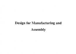
Fig. 2 Classification of design/ manufacturing interface [24]
2.4 Design and manufacturing interface Concerning design and manufacturing interface, various scientific papers are focussed on CAD-CAM integration. They provide solutions for exchanging data based on standards (e.g. STEP-AP203); nevertheless, that standard is not currently defining experts’ concepts but only from features. Moreover, STEP standards cannot be changed easily and dynamically to add some new concepts concerning product modelling. Some results are based on feature recognition [21]. Other papers propose the integration of manufacturing system constraints [22] but it is not really the same as manufacturing process constraints as considered in the paper. Twigg [23] gives a more generic overview of what could be mechanisms for design and manufacturing interface and classify the different problems that should be faced (cf. Fig. 2). The research work presented here focuses on the design phase and could be used to tackle A5, A6, A7 and D3. As shown on the Fig. 1, the authors describe a specific structure to achieve the manufacturing information synthesis in design. That model is called an interface model, which is necessary because it represents only a few parts of the whole expert knowledge, but then has to be translated. Skin and skeletons concepts are then used to define the interface model. Those concepts have already been presented in the literature to ensure a description of product functional surfaces. In [24] and [25] the authors define skeleton features as skins links. Skeletons corre-
Design
Design
Processes Selection
Processes Selection
Processes Selection
Manufacture (CAM)
Manufacture (CAM)
Manufacture (CAM)
Design (CAD)
1/ Traditional design process
2/ Process selection and manufacturing information synthesis
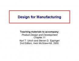
the models developed. Figure 3 presents the objectives and benefits of our contribution. In the current design process (Fig. 3 column 1) there are very few feedbacks from “processes selection” to “design” (i.e. CAD modelling). The presented approach defines new models to support that kind of back loop (Fig. 3 column 2). Further on, the “processes selection” activity moreover should lead to a list of eligible process plans that also clearly impact the design activity proposing several design alternatives (Fig. 3 column 3). Each manufacturing process plan then constrains a design solution. After detailing those benefits in the next sections an illustration is given (see Fig. 10).
3/ Design and manufacturing alternatives
Fig. 3 Method benefits
spond to neutral material fibre and define part material topology. In [26] and [27] the authors describe a method for representing objects, they also use the notion of skeletons defined by the central axis of objects and shapes that cover the skeleton. The aim of the aforementioned research is a representation of object motion for robotic studies. With regard to these works, the next section specifies skin and skeleton concepts with a specific set of attributes that ensure design/manufacturing interface modelling and let the product emerge by least commitment instead of being centred on CAD modelling.
3.1 Method for knowledge synthesis According to the general framework of integrated design (Fig. 1), the proposed synthesis approach has been based on a formal analysis and representation of design expert activity. This work is specifically based on the manufacturing process selection activity in order to give, as soon as possible, recommendations to CAD models (Fig. 3). For instance, from the same required functional surfaces, a final CAD model may not be similar depending on forging, casting or milling process. With respect to IDEFØ modelling (Fig. 4), that activity (A-0) is split into two main tasks:
3 Knowledge synthesis method and design/ manufacturing interface modelling
– According to fundaments issued from the previously given survey, this section presents the details of the method and
A1: to characterize the interface model. The expert must first take into account the already-specified requirements coming from other members of the design group. Those
List of products alternatives solutions (definition of : geometry, tolerance, etc)
Design Manufacture requirements requirements
Resources productprocesses
Characterize interface model A1 Attributes values of Manufacturing interface model
Humans resources : DFM Actor
Interface model (evolve in the synthesis loop)
Design and manufacture requirements
Manufacturing processes List
Materials Resources requirements productprocesses
Select processes and identify manufacturing plans and their constraints
List of manufacture processes alternatives List of manufacture processes constraints List of plans alternatives
A2 Humans resources : DFM Actor
Manufacturing constraints synthesis (data flow)
Fig. 4 Main activities of knowledge synthesis method (IDEFØ model)
Attributes values of Manufacturing interface model
–
requirements are modelled using what the author calls a usage interface model (see Sect. 3.3.2). This model is therefore the input of A2, where only the two lateral plane surfaces are specified (i.e. usage) (see Fig. 10). A2: to select manufacturing processes and to identify process plans and their constraints. With respect to the requirements (i.e. interface model), the expert realises the first manufacturing process selection. The output is a set of process plans and their respective information (tolerances, roughness, etc.). That information is described using the manufacturing interface model and then fed back to the shared kernel of information. That feedback is then used either to add extra information (and associated range of values) on the product that has to be shared for the collaborative decision making process or to constrain the alreadydefined information range of values. The shaped surface was not defined as requirements but described
Design requirements
–
according to manufacturing information (see Fig. 10). Those surfaces’ characteristics (IT, Ra) therefore depend on process selection. A synthesis loop is defined between those two activities to model the fact that the integrated design process is no longer sequential. Requirements are then evolving each time an expert integrates new information. The interface model is then evolving too and the expert can therefore run a new manufacturing process selection task to either refine his first solution or to validate that new requirements are still coherent with the first selection. The final design solution takes into account the manufacturing information and is really based on knowledge synthesis and not only on CAD model assessment. This new CAD modelling approach based on experts’ knowledge (e.g. manufacturing) respects experts’ requirements “the first time” versus a “redo until right” process.
Resources product
Identify usage interface model
Attributes values of designed product List of products alternatives solutions (definition of : geometry, tolerance, etc) (if inclusion relation verified)
A11 Humans resources : DFM Actor
Apply inclusion relation (Designed product is included in manufacturing product) Manufacture requirements
Attributes values of Characterize manufacture interface Manufactured product model
A12 Attributes values of Manufacturing interface model
A13
Resources processes
Humans resources : DFM Actor
Fig. 5 A1 activity decomposition. Identification of the interface model requirements
Humans resources : DFM Actor
Interface model (evolve in the synthesis loop)
coherency in the synthesis (i.e. integration) loop as previously enounced.
The activities A1 and A2 manage data flows representing design and manufacture requirements, product and process data resources, etc. This management consists of: – – –
Design information analysis: study of technological components constraints and elaborate a product model [28]. Manufacturing processes analysis: choose processes alternatives and analyse manufacturing processes to identify constraints. Creation of method and model of manufacturing processes selection and constraints synthesis (integration).
This IDEFØ modelling makes decomposition of every task into several ones possible at different granular levels. Accurate details of the entire activity modelling can be found in [29]. For example, A1 activity (Fig. 5) is broken down into: – – –
A11 Identify usage interface model from already existing requirements in the shared kernel of information. A12 Characterize manufacturing interface model based on manufacturing process selection (A2). A13 Apply inclusion relation (design product is included in manufacturing product) to keep the
The usage interface model is not modifiable in A-0; it is then A11 activity control information. Manufacturing interface model is on the contrary refined in A-0, it is the result of manufacturing attributes range of values synthesis; this information is an input for A12 activity. The inclusion relation (A13) is defined as: “designed (i.e. required) product has to be included in manufacturing solution (i.e. manufactured product)”. In fact, the manufacturing solution must include the required (design and functional) specifications and other specifications that result from other expertises. This relation is given by a rules and relations list between both “usage” and “manufacturing” interface model attributes. For example, the roughness value that can be realised by a selected process must be lower than the required roughness value. With respect to the activity IDEFØ model, it is then easy to identify static concepts used while processing the knowledge synthesis method. The next step of the research work is therefore to propose a static design view of the information structure. To do so, the authors use UML
Illustration Usage Skin 1
*
1
-Name : char -Author : char +Create and initialize() +Notify()
is made up of 1..*
Prodcut Alternatives
*
Process plan Alternatives +Create plan() +Notify() 1
Manufacture 1
is defined by
1
is defined by
1..*
*
is constituted of Process
-Name : char
-Name : char
1..*
is illustrated by * 1 is described by 1
1
is made up of 1 1..*
Usage Skeleton
Description
Operation Number
Project.
1
1..*
Skeleton portion -Name : char -Initial section form : Section Form -Final section form : Section Form -Section variation : Section Variation -Neutral fibre : Neutral Fibre -Skeleton material direction : int
Manufacturing Skeleton
-Name : char +Create() +Notify Process()
1
1..*
is made up of 1* 1
1..*
Skeleton Covering
1 1
1
Manufacturing Skin
Processes Selection
Skeleton
Skin
-Name : char -Initial section form : Section Form -Final section form : Section Form -Section variation : Section Variation -Neutral fibre : Neutral Fibre -Skeleton material direction : int
-Name : char -Shape : Skin Shape -Ra : float -IT : float -Skin material direction : bool
1
1
Use
is based on
Attribute Value
is characterized by * *
is characterized by
1
has a type 1
1
*
*
Technology
Value Type
Physical Principle
Skeleton Attributs is parameterized by 1 * Constraints Integration Integer Section
Real
Parameter
Skin Attribute
Neutral Fibre is limited by 1 1..*
1
1 is defined by 1
Section Form
Section Variation
Fig. 6 Presentation of modelling concepts with UML class diagram
Skin Shape
limit
1
Constraints
1
formalism (Unified Modelling Language) [30] and, specifically, the class diagrams. That information modelling method is very similar to knowledge management approaches. They first give an overview of the activity and then extract the static concepts (i.e. knowledge) [31]. That work has also been supported by specifying scenarios (sequence diagrams) of the design method (see Fig. 8). 3.2 Design and manufacturing interface model for manufacturing knowledge synthesis 3.2.1 Concepts overview From IDEFØ formalism (input, control, mechanism and output information), information modelling concepts are extracted: – – – – –
–
Human resources: experts that run the “manufacturing process selection” activity (A-0). Product solution alternatives: list of potential design solutions resulting from experts’ constraints integration. Manufacturing processes database. Process plan alternatives: list of eligible process plans that result from selected processes. Design/manufacturing interface model: model that simultaneously supports product and manufacturing information in order to achieve the manufacturing information synthesis during the design process. Information resources of product, processes and product/processes: all product and process information used in the product definition. That information concerns either physical parameters or technological parameters.
These concepts have then been structured and presented in a UML class diagram. Relations, attributes and operations (Fig. 6) are also detailed. The class diagram is made up of two parts: –
–
Interface model that represents the minimal information required to process the synthesis in design as presented in Fig. 1. The authors use skin and skeleton features and specific attributes to depict that model. Manufacturing data model that represents manufacturing process selection information. That information, as expert information, has a priori not to be shared among the design group. It would be shared only if needed by another expert.
Relationships between the two models are represented by “processes selection” and “constraints integration” associations with respect to common skin and skeleton attributes.
The “project” class is made up (aggregation relation) of “product alternatives” and “process plan alternatives” classes. To define product model, skin and skeleton features are used and represented in the diagram by the skin and skeleton classes and their inheritance classes “usage skin”, “usage skeleton”, “manufacturing skin” and “manufacturing skeleton” (the diagram does not represent all the inheritance links of skin shape, section shape, section variation, and neutral fibre for clarity reasons). 3.2.2 Skin and skeleton feature definition As introduced above, the interface model supports synthesis of both design and manufacturing specifications. This model allows emergence of product solutions that respect manufacturing constraints. To describe the interface model authors use specific skin and skeleton features. According to the literature review and the definition of the interface model, generic concepts of skin and skeleton have first been defined. Skins must describe the product’s functional surfaces and skeletons describe trajectory of flow. Secondly, two kinds of specific (i.e. multiple representations) of skin and skeleton features have been detailed: usage features (i.e. design requirements) and manufacturing features [32]: –
Usage skin: surface through which energetic flows circulate [33]. Usage skins are defined by functional surfaces resulting from technological components selection (e.g. ball bearing coupling, poles of a magnet,
Skeleton Trajectory = magnetic flow
Skeleton section
? “U” Magnet
+
-
Skin topology = surfaces crossed by the magnetic flow
Usage interface model = requirements
Skeleton trajectory = material flow
Skeleton section Manuf. Solution 1
Manuf. Solution 2
Manufacturing interface model = manufacturing information modelling
Fig. 7 Skin and skeleton illustration: example of alternative solutions of a “U” magnet manufacturing
Usage skin
EXE
Usage skeleton
Processes DB
DFM actor Execute
Create
HMI
Show windows() New project()
Create and initialize
Project Notify values (Name, shape, Ra, IT, skin material direction)
Show skin and skeleton attributes values ()
Notify skin and skeleton attributes values ()
Notify values (Name, Section form, Section variation, Neutral fibre, skeleton material direction) Look up primary processes ()
Create
Notify processes with their skin and skeleton attributes limit values ()
Process Show process list and their limit values ()
Select processes ()
Notify Processes () Notify selected processes ()
Notify Processes ()
Notify Processes ()
Create ()
Process plan Alternatives Gamme
Notify process plans list () Show process plans list () Inform manufacture skeleton attributes values ()
Notify process plans list ()
Notify manufacture skeleton attributes values ()
Create ()
Manufacture skeleton
Create () Create ()
Manufacture skin Product alternatives
Notify manufacture skeleton () Notify manufacture skin ()
Show all process plan shape ()
Create shape ()
Notify product shape alternatives solutions ()
Fig. 8 Example of UML sequence diagram
–
–
etc.). These skins support geometric attributes and tolerances. Usage skeleton: trajectory of an energetic (mechanical, electrical, magnetic, etc.) flow circulating in the product (e.g. see, for example, Fig. 10 where the U trajectory represents that skeleton specified by designers according to specific required magnetic behaviour). Manufacturing skeleton: material flow trajectory processed during manufacturing. Indeed authors make the hypothesis that every manufacturing process is based on a material flow (e.g. casting or injection moulding create material, machining removes material, forging deforms material).
–
Manufacturing skin: surface generated by a manufacturing process. These features are partly issued from manufacturing skeletons by a sweeping operation (e.g. surfaces issued from a pocketing milling operation can be defined by sweeping the end mill tool section on its trajectory. The shaped surface is issued from both extrusion and drilling processes, cf. Fig. 10). In the case of deformation based processes, the manufacturing skin is not deducted from the sweeping operation but from deformation algorithms.
Owing to the manufacturing skeleton concept, material flow can be globally (i.e. part level) or accurately (i.e. tool
Fig. 9 Graphic user interface of the software demonstrator
level) described depending on the detail of information that has to be taken into account in the design process. Figure 7 presents an example of usage and manufacture skins and skeletons to model the product solution of what could be a “U” magnet. The required solution is not totally defined and would then be constrained by manufacturing interface modelling coming from the manufacturing process selection task. Several design alternatives are then available. Specific sets of attributes are associated with skin and skeleton features: – –
Skin attributes are shape (cylinder, plane, etc.), tolerance, roughness and material direction (depending on the form). Skeleton attributes are initial section form, final section form (circular, rectangular, etc.), section variation (follow variation law: null, increasing, decreasing, etc.), neutral fibre (line, curve, plate, etc.).
For manufacturing skeletons, an extra attribute defines the material flow direction that could be set as: removal (e.g.
machining), addition (e.g. casting) or deformation (e.g. forging, stamping). Based on that simple concept it is very easy to analyse what could be the final part definition based on manufacturing process selection. Indeed, the final 3D model of a part (made of manufacturing skins) is constructed by sweeping (Fig. 7) or deforming the skeleton section on the skeleton trajectory. The initial model described with “usage” skin and skeleton can be compared to the “manufacturing” one. The main benefit of these modelling concepts is that the manufacturing knowledge is taken into account very early in the product development process (and the CAD modelling) instead of waiting for an initial CAD model which would be modified afterwards. 3.3 Software demonstrator In order to support the knowledge synthesis approach, a software demonstrator has been developed to manage the UML model presented above. It is specified using a UML
Fig. 10 Examples of the knowledge synthesis approach using skin and skeleton modelling
Examples
Examples of usage Examples of manufacturing solutions: interface modelling manufacturing interface modelling Example 1 : cube-shape creation Neutral fibre.
Initial and final section forms.
The expected part has cube-shape. Design requirements are described with two usage skins and one usage skeleton features. Features attributes are represented by UML classes.
Initial and final section forms (rectangular).
Usage Skin
Manufacturing Skin
Name : U-Skin 1 Shape : Rectangle Roughness : 3,2 Tolerance : IT7 Skin material direction : +
Name : M-Skin 1 Shape : Cube-shaped Roughness : 3,2 Tolerance : IT7 Skin material direction : +
Manufacturing skin.
Usage Skin
Manufacturing Skeleton
Name : U-Skin 2 Shape : Rectangle Roughness : 3,2 Tolerance : IT7 Skin material direction : +
Name : M-Skeleton 1 Initial Section form : Rectangle Final section form : Rectangle Section variation : Null Neutral fibre : Rectilinear Skeleton material direction : Material addition
Usage Skeleton Name : U-Skeleton 1 Initial Section form : Rectangle Final section form : Rectangle Section variation : Null Neutral fibre : Rectilinear Skeleton material direction : Material addition
An example of selected manufacturing process is: Extrusion. Note: the rectangular section is represented by length, breadth and radius (related to process specification). Example 2 : holed cube Neutral fibre.
Initial and final section forms (circular).
The hole is represented by cylindrical usage skin.
Usage Skin
Manufacturing Skin
Name : U-Skin 3 Shape : Cylinder Roughness : 6 Tolerance : +-0.4 Skin material direction : -
Name : M-Skin 2 Shape : Cylindrical Roughness : 6 Tolerance : +-0.4 Skin material direction : -
Manufacturing Skeleton Name : M-Skeleton 2 Initial Section form : Circle Final section form : Circle Section variation : Null Neutral fibre : Rectilinear Skeleton material direction : Material remove
An example of selected manufacturing process to make the hole is: Drilling.
sequence diagram (Fig. 8). This diagram presents specifications of chronological actions of a user on the software demonstrator. It combines IDEFØ diagram activities and class diagram static concepts. Software developments have been based on the C++ language in the MS Visual 6.0 environment. Figure 9 presents an actual graphic user interface used to: – – –
Manage processes information (technological, physical, etc.) in order to select processes. Model product (based on skin and skeleton) alternatives issued from manufacturing process alternatives. Show product’s form features (i.e. shapes) in a 3D viewer developed with Open CASCADE libraries. It is then possible to compare design requirements (requirements specifications) and manufacturing alternatives (final solution).
ing process representation). Material selection and economic parameters are obviously linked to that examined but not formalized in the paper. The software demonstrator ensures product design assistance. The result is the emergence of the product definition with manufacturing constraints and reduction of design/manufacturing iterations. The first recommendation for further work concerns the creation of process knowledge structure with respect to the specified manufacturing data model and using existing databases like CES41. Generalization of the method and model to other expertise fields (recycling, assembly, etc.) could also be investigated to enlarge the DFX framework.
Acknowledgement This research is part of the regional French project IFP2R: “Manufacturing constraints integration in rapid prototyped part design” with IFTS (Higher Technical Formation Institute of Charleville Mézières- France).
4 Illustration Figure 10 presents two examples of a skin-skeleton model. First, an example of usage representation indicates the expected part (shape form, roughness, tolerance, etc.) issued from functional analysis. Second, the manufacturing process selection provides the manufacturing skeletons and manufacturing skin (generated by skeleton covering and represents manufactured part). Manufactured part solutions must conform to the inclusion relation. In fact, manufacturing solutions do not necessarily have the same attribute values of usage solutions (shape form, roughness, tolerance, etc.) but must include them, so these solutions can be different. It should be noted that the proposed solutions represent only the manufacturing point of view. The skin and skeleton model could be enlarged and used to study other expert activities (Fig. 1).
5 Conclusion and recommendations for further work This research work presents a new knowledge synthesis method that aims at integrating manufacturing constraints as early as possible during the product definition. The approach is based on two principal stages: processes selection and progressive integration of manufacturing constraints. To do so the authors present a method supported by a design/manufacturing interface model that uses skin and skeleton features specified in usage (i.e. design data issued from components selection) and manufacturing (i.e. data related to manufacturing processes). This model includes two parts: product interface model (product representation) and manufacturing data model (manufactur-
References 1. Sohlenius G (1992) Concurrent engineering. CIRP Ann 41 (2):645–655 2. Tichkiewitch S, Veron M (1997) Methodology and product model for integrated design using a multiview system. CIRP Ann 46(1) 3. Alting L, Legarth JB (1995) Life cycle engineering and design. CIRP Ann 44(2) 4. Kuo Tsai-C, Huang SH, Zhang H-C (2001) Design for manufacture and design for ‘X’: concepts, applications and perspectives. Comput Ind Eng 41:241–260 5. Nowak P, Rose B, Saint-Marc L, Callot M, Eynard B, GzaraYesilbas L, Lombard M (2004) Towards a design process model enabling the integration of product, process and organization. Presented at the 5th international conference on integrated design and manufacturing in mechanical engineering - IDMME’2004, Bath, UK 6. Krause FL, Kind C (2005) Simulation approaches to optimise the management of product development processes. In: Weiss Z (ed) Virtual design and automation. Publishing House of Poznan University of Technology, Poznań, Poland 7. Ong SK, Sun MJ, Nee AYC (2003) A fuzzy set AHP-based DFM tool for rotational parts. J Mater Process Technol 138:223–230 8. Poli C (2001) Design for manufacturing: a structured approach. Butterworth-Heinemann, UK 9. Swift KG, Brown NJ (2003) Implementation strategies for DFM. P I Mech Eng B J Eng 217:827–833 10. Lovatt AM, Shercliff HR (1998) Manufacturing process selection in engineering design. Part 2: The role of process modelling. Mater Des 19:217–230 11. Boothroyd G, Dewhurst P, Knight W (2001) Product design for manufacture and assembly, 2nd edn. Marcel Dekker, New York 12. Swift KG, Booker JD (2003) Process selection: From design to manufacture, 2nd edn. Butterworth-Heinemann, UK
1
http://www.grantadesign.com
13. Ashby MF, Brechet Y, Cebon D, Salvo L (2004) Selection strategies for materials and processes. Mater Des 25:51–67 14. Esawi AMK, Ashby MF (2003) Cost estimates to guide preselection of processes. Mater Des 24:605–616 15. Edwards KL (2003) Designing of engineering components for optimal materials and manufacturing process utilisation. Mater Des 24:355–366 16. Shah J (1991) Assessment of feature technology. Comput Aided Des 23(5):55 17. Krause FL, Kimura F, Kjelberg T, Lu SC (1993) Product modelling. CIRP Ann 42(2) 18. Kjelberg T, Schmekel H (1992) Product modelling and information-integrated engineering systems. CIRP Ann 41(1) 19. De Martino T, Falcidiano B, Hassingert S (1998) Design and engineering process integration through a multiple view intermediate modeller in a distributed object-oriented system environment. Comput Aided Des 30(6):437–452 20. Roucoules L, Noël F, Teissandier D, Lombard M, Debarbouillé G, Girard P, Merlo C, Eynard B (2006) Ippop: an Opensource collaborative design platform to link product. Presented at design process and industrial organisation information, IDMME’2006, Grenoble, France 21. Miao H, Sridharan N et al (2002) CAD-CAM integration using machining features. Int J Comput Integr Manuf 15(4):296–318 22. Zifang W, Yan X-T et al (2004) Proactive support for product conceptual design incorporating manufacturing system considerations. In: Yan X-T, Jiang C-Y, Juster NP (eds) Perspectives from Europe and Asia on engineering design and manufacture. Kluwer Academic, Stockholm Sweden, p 782 23. Twigg D (2002) Managing the design/manufacturing interface across firms. Int J Integ Manuf Syst 13(4):212–221
24. Muh-Cerng W, Wu TY (1993) A skeleton approach for modelling assembly products. J Des Manuf 3:121–133 25. Tollenaere M, Belloy P, Tichkiewitch S (1994) A part description model for the preliminary design. Presented at feature modeling & recognition in advanced CAD/CAM systems, IFIP international conference. Valencienne, France, pp 143–159 26. Song CZ, Yuille AL (1996) FORMS: A flexible object recognition and modeling system. Int J Comp Vision 20(3):187–212 27. Ogniewicz RL (1994) Skeleton-space: a multiscale shape description combining region and boundary information. In: Proceedings of CVPR’94, Seattle, WA, pp 746–751 28. Klein-Meyer JS, Roucoules L (2006) Assessment of a functional and DFX approach for mems design. In: Proceedings of integrated design and manufacturing in mechanical engineering conference (IDMME’06), Grenoble, France 29. Skander A (2006) Méthode et modèle DFM pour le choix des procédés et l’intégration des contraintes de fabrication vers l’émergence de la solution produit. PhD Thesis, University of Technology of Troyes 30. Booch G, Rumbaugh J, Jacobson I (1999) The unified modeling language user guide. Addison Wesley, Upper Saddle River, NJ, USA 31. Ermine JL (2003) La gestion des connaissances. Hermès Science, France 32. Roucoules L, Skander A (2003) Manufacturing process selection and integration in product design. Analysis and synthesis approaches. In: Proceedings of the CIRP design seminar 2003, Grenoble, France 33. Roucoules L, Tichkiewitch S (2000) CoDE: a cooperative design environment. A new generation of CAD systems. CERA 8 (4):263–280