DESIGN AND MODELING OF AN ASYNCHRONOUS OPTICAL PACKET SWITCH FOR DIFFSERV TRAFFIC W. Vanderbauwhede, D. A. Harle Broadband and Optical Networks group Institute of Communications and Signal Processing Department of Electronic and Electrical Engineering University of Strathclyde, Glasgow G1 1XW, UK
[email protected],
[email protected]
Abstract
1. 1.1
In this paper, we discuss the design and modeling of the OPSnet asynchronous optical packet switch. We focus on traffic modeling and the integration of DiffServ per-hop-behaviour in the optical packet switch architecture. We demonstrate the influence of traffic shaping, traffic aggregation and DiffServ prioritisation on the performance of the switch using simulation results, and present an analytical model to quantify the drop probability for the various DiffServ classes as a function of the class mix and the buffer depth.
Introduction Asynchronous optical packet switching
The OPSnet project [1] is an EPSRC-funded collaboration between the universities of Strathclyde, Essex and Cambridge with participation from a number of industrial partners (BT Laboratories, Fujitsu Telecommunications, Marconi). Like its predecessor, WASPNET [2], the project aims to bring the packet switching concept into the optical domain. Although in the near future, high-capacity circuit-switched optical transport networks will be available, optical packet switching still maintains its attraction. Economics will always demand that network resources are used efficiently. A major advantage of packet switching lies in its bandwidth efficiency and ability to support diverse services. The WASPNET project demonstrated a prototype switch with a synchronous, SDH-like architecture. Motivated by, in part, the increasing deployment of fast Ethernet in access networks, OPSnet investigates the merits of direct asynchronous optical packet switching of variable length (Ethernet-like) packets. This type of optical packet switched networks can network can also offer excellent QoS support using techniques like DiffServ over GMPLS.
2
1.2
Quality of Service
QoS (Quality of Service) often pre-supposes that throughput, loss, delay, jitter etc can be, to some extent, guaranteed in advance. QoS is of particular concern for the continuous transmission of high-bandwidth video and multimedia information. Transmitting this kind of content dependably is difficult in networks using ordinary "best effort" protocols. One of the solutions proposed to guarantee QoS in optical networks is to use DiffServ over GMPLS [3].
1.3
GMPLS
Generalized Multi-Protocol Label Switching (GMPLS) is an extension or generalization of MPLS [4] that allows a label to be, amongst others, a wavelength or position in space [5, 6]. The basic idea behind MPLS is to pre-establish paths along which the data will be forwarded. This connection-oriented approach with bandwidth reservation for the so-called Label-Switched Path (LSP) is an essential requirement for QoS.
1.4
DiffServ
Furthermore, to guarantee a certain QoS level, it must be possible to prioritise the traffic. The differentiated services (DiffServ) standard [7] was developed by the Internet Engineering Task Force to provide a common methodology for implementing priority-based QoS. The standard defines three main traffic classes: Expedited Forwarding (EF), Assured Forwarding (AF) and Best Effort (BE). The EF class has the highest priority. The AF group is further divided into four independent AF classes. Within each AF class, an IP packet is assigned one of three different levels of drop precedence. AF packets of any precedence can be dropped or delayed to give priority to an EF packet. Best Effort traffic has, by definition, no QoS requirements and, as a result, prioritisation of EF and AF traffic will be done as much as possible at the expense of the BE traffic.
2.
OPSnet Architecture and DiffServ Integration
The OPSnet optical packet switch (OPS) architecture has been reported extensively elsewhere [8, 9]. In this section, aspects relevant to the traffic modeling are now briefly discussed.
2.1
OPSnet asynchronous Optical packet Switch architecture
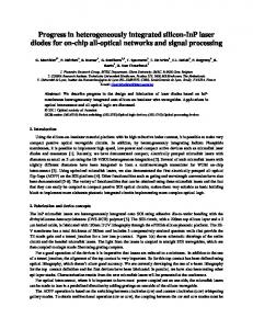
The OPSnet OPS (Fig. 1) uses statistical multiplexing with optical buffering for contention resolution. The buffer modules are placed on the input ports (inline buffering), and all packets are buffered by default. This approach facilitates packet-order control. Each buffer module consists of a parallel array of per-packet recirculating buffers 2. An electronic buffer control system keeps track of free and occupied buffers, and decides when a packet can leave its buffer. The per-packet
Design and Modeling of an Asynchronous Optical Packet Switch for DiffServ Traffic3
Figure 1.
OPSnet optical packet switch concept
recirculating buffers are based upon a novel design and are called multi-exit buffers. This type of buffer has a greatly enhanced egress probability compared to fixed-length, single-exit recirculating buffers. The combination of the parallel architecture with the multi-exit buffer design leads to a buffering system with a very low latency.
Figure 2.
OPSnet buffer architecture
The innovative approach allows the packet to leave the recirculating buffer loop at more than one point, resulting in a much improved egress probability. The complete system, including the control, is fully asynchronous, with every packet being processed in a separate ”hardware thread”.
4
2.2
DiffServ Integration
To support the DiffServ standard, the OPS control system must implement the DiffServ per-hop behaviour, which means controlling the packet loss, delay and ordering. Obviously the OPS must be designed to allow this degree of control. This means that an OPS which cannot conserve packet ordering can not be DiffServ compliant.
2.2.1 Packet loss prioritisation. According to the DiffServ specifications, the packet loss requirements are most stringent for EF traffic and most relaxed for BE traffic. The four AF classes are further subdivided in three drop precedence levels. To prioritise the drop behaviour of the OPS, a pre-emptive drop mechanism has been implemented (Fig. 3): If the buffer is full when a packet arrives, check the packet class. For non-BE packets, drop a packet from a lower class, starting with BE. If no BE packets available: – if the arriving packet belongs to an AF subclass, drop a packet with a lower drop precedence, if any. Otherwise, drop the packet itself. – if the arriving packet belongs to the EF class, drop the packet with the lowest drop precedence of any AF subclass, if any. Otherwise, drop the packet itself. BE packets are dropped immediately. To implement such a mechanism, the buffer control system needs to keep track of the buffer addresses for all packets. This is implemented as a series of FIFO’s (one per class/subclass/drop level).
2.2.2 Packet order conservation. The OPSnet OPS has been designed to be able to conserve packet ordering, which is the main reason why all packets are always buffered by default. However, the DiffServ specification requires only conservation of packet order within the EF class and every individual AF class. There is no requirement to conserve the ordering for best effort traffic. As conserving the packet order increases the latency, no attempt is made to do this for BE traffic. This also has a beneficiary effect on the total packet loss, as conservation of the packet order requires a higher buffer depth, thus resulting in higher packet loss for a given buffer depth. The switch control system differentiates between the traffic classes by keeping the buffer addresses in separate FIFO’s. Only packets at the head of the FIFO queue are allowed to leave the buffer. 2.2.3 Packet delay prioritisation. As explained above, the OPSnet OPS has, by design, a negligible latency. Consequently, there is no need to prioritise the packet delay. In principle, the control system used to conserve
Design and Modeling of an Asynchronous Optical Packet Switch for DiffServ Traffic5
Figure 3.
Pre-emptive drop scheme
the packet order could be extended to prioritise the packet delay by imposing an extra priority rule on the FIFO exit. But this leads to a more complicated control system while providing no performance gain.
2.3
Improving the Network Performance by Traffic Aggregation
One of the important design decisions for the OPSnet network was that ingress routers (developed in the frame of the EPSRC project OPORON [11]) would perform traffic aggregation. Packets belonging to a common GMPLS LSP and DiffServ class are combined into an extended packet. This results in a reduction of the self-similarity of the traffic (the resulting distribution is more Poisson-like), and a more efficient bandwidth utilisation. However, the mean of the packet length distribution shifts towards the maximum packet length, and the switch design, in particular the buffer design, must be capable of handling this. As the egress probability of the OPSnet multi-exit buffer design is independent of the packet length, the switch performs well with aggregated traffic, as the simulation results in section 4 demonstrate.
3.
Choosing the Right Traffic Model
When evaluating the performance of a switch, the use of realistic traffic models is essential. In the case of an asynchronous optical packet switch for packets with variable length, modeling the traffic is not straightforward as the packet buffering leads to considerable traffic shaping. In this section, we discuss
6 the impact of the distribution of the inter-arrival times and in particular of the steady-state core traffic obtained by the traffic shaping properties of the OPSnet switch.
3.1
Ingress Traffic model
The models for traffic entering the network are based upon a 2-state model as shown in Fig. 4. Packet length distributions are taken from uniform, fixed and IP-like distributions [10] while the gaps between packets follow one of uniform, negative exponential (Poisson) and power-law (Pareto) distributions. To ensure fairness when comparing overall performance, all three packet gap distributions have common minimum and mean gap intervals. Simulated distributions of the inter-arrival times for these traffic models are shown in Fig. 6.
Figure 4.
3.2
Traffic distribution model
Steady-State Core Traffic Model
The OPSnet OPS architecture has a very strong traffic shaping effect and thus it is necessary to model the steady-state core traffic distribution. This steady state is achieved by queuing the switched packets in lines with a length equal to the average link length, changing their destination labels and switching the streams back to the OPS using a random multiplexer (Fig. 5).
Figure 5.
Core traffic simulation strategy
Such an approach is equivalent to connecting a number of OPS within a network topology where the average load per node is uniform over the network. By maintaining a high overall network/node load, such a configuration can be
Design and Modeling of an Asynchronous Optical Packet Switch for DiffServ Traffic7
used to evaluate the performance of an OPS-based transport core network. The overall network performance can then be characterised by the aggregated losses and latencies of individual switches. Simulated distributions of the inter-arrival times for the steady-state core traffic model and Pareto and Poisson ingress traffic are shown in Fig. 6. The distribution as shaped by the optical packet switch is independent of the ingress distribution: seeding with Pareto, Poisson and uniform traffic gives identical results.
Figure 6. Distributions of the inter-arrival times for the steady-state core traffic model and Pareto and Poisson ingress traffic
4.
Simulation results
The results in this section are obtained using a high-level OPS node simulator developed as part of the OPSnet project. This discrete-event simulator can be configured to use different traffic models, varying numbers of ports and buffer depths, different buffer designs and buffer control strategies.
4.1
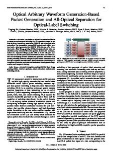
Steady-state Core Traffic versus Ingress Traffic
Fig. 7 shows a comparison between ingress traffic with Pareto-distributed inter-arrival times and steady-state core traffic. The graph shows the packet loss as a function of the buffer depth for a load of 0.8. The impact of the traffic shaping is very clear: the packet loss is about three orders of magnitude lower for steady-state core traffic.
4.2
Impact of Traffic Aggregation on Packet Loss and Latency
As discussed earlier, it is important to evaluate the influence of DiffServ traffic aggregation on the core OPS performance, primarily in terms of packet
8
Figure 7.
Comparison between Pareto and steady-state core traffic
loss and latency. Fig. 8 shows the packet loss reduction as a result of aggregation for a load of 0.8. For the purpose of illustration, the absolute loss has been artificially increased by using a low buffer depth of only 16 buffers.
Figure 8.
Effect of traffic aggregation on packet loss
Another important performance indicator is the packet latency. The effect of aggregation on the packet latency is illustrated in Fig. 9. It might seem surprising that packet aggregation leads to lower latency, given that the resulting
Design and Modeling of an Asynchronous Optical Packet Switch for DiffServ Traffic9
packets are longer. However, the aggregation leads to a lower number of packets for the same load; moreover, the egress probability of the multi-exit buffer does not depend on the packet length. The simulations results show that less than 1 packet per million has a latency of more than 4µs (at 100Gb/s). As the typical latency specifications for delay-sensitive applications like VoIP or video are less than 100ms (ITU-T Recommendation G.114 [12]) , it is clear the latency of the OPSnet optical packet switch is negligible.
Figure 9.
4.3
Effect of traffic aggregation on packet latency
Buffer Dimensioning
The required buffer depth for a given packet loss depends on the traffic distribution and the network load, as well as on the particular buffer design. We assume a ”heavy” average network load (defined as mean packet length / mean inter-arrival time) of 80%. The results of the traffic study as discussed above show that a realistic traffic model for the OPSnet optical packet switch must take into account the following factors: The real traffic will be a mixture of ingress traffic and steady-state core traffic. For this work, we assume that the average order of the network is 3, which implies that one out of four ports is an ADD port. The ingress traffic is aggregated into 3000-byte extended packets with a Poisson-like inter-arrival time distribution. The results of simulations of the packet loss as a function of the buffer depth for different loads are shown in Fig. 10. The maximum acceptable packet loss can be estimated as follows:
10 The ITU-T Recommendation Y.1541 [13] specifies an upper bound on the IP pack loss probability of 10−3 . An aggregated packet contains on average 10 IP packets (this is due to the abundance of 40-byte ACK packets). We assume that the maximum number of hops between OPS’s in the core network is 10. Using (1 − δ)n ≈ 1 − n.δ, the maximum acceptable packet loss for the OPS is 10−5 . For a load of 0.8, the required buffer depth according to Fig. 10 is 24. 66
Figure 10.
4.4
Packet loss versus buffer depth for varying network load
Impact of Packet Order Conservation on the Packet Loss
Conservation of packet order requires a higher buffer depth, thus resulting in a higher packet loss for a given buffer depth, as illustrated in Fig. 11. However, the required increase in buffer depth to compensate for the packet ordering is not very high (from 24 to 36 for a packet loss of 10 ppm). Packet order conservation is required for the EF and AF DiffServ classes. However, to have efficient prioritisation, the largest portion of the traffic must still consist of BE packets. Therefore, the effect of the packet order conservation will be small, and the behaviour will be close to the unordered case.
Design and Modeling of an Asynchronous Optical Packet Switch for DiffServ Traffic11
Figure 11.
4.5
Effect of conservation of packet order on packet loss
DiffServ Prioritisation
Fig. 12 shows the preliminary simulation result of the effect of pre-emptive drop strategy on EF class packet loss as a function of the network load. For the purpose of illustration, the packet loss has been exaggerated by keeping the buffer depth low.
Figure 12.
Effect of pre-emptive drop on EF class packet loss
12
5.
Analytical model for the DiffServ packet drop probabilities
The packet loss probability for each DiffServ class is the product of two terms: the first term is the probability for buffer overflow, and the second is the probability that a packet of a certain class will get dropped. First we define the probabilities of arrival at the buffer for the different classes as αEF , αAF,i , αBE for the three main classes and βi,0 , βi,1 , βi,2 for the AFi drop levels with αEF +
3 X
αAF,i + αBE = 1
(1)
i=0
and 2 X
βi,j = 1
(2)
j=0
Furthermore, let AFj ≡
4 X
αAF,i .βi,j
(3)
i=1
As discussed earlier, the probability for buffer overflow is influenced by the conservation of the packet order. Consequently, changing the DiffServ mix will change the overall packet loss. In practice, all EF and AF packets must remain ordered, so the probability for buffer overflow can be approximated as: Pf ull = Pf ull,ordered .(αEF +
X
αAF,i ) + Pf ull,unordered .αBE
(4)
i
The probability that a packet of a certain class will get dropped when the buffer is full depends on the probability of packets with a lower drop precedence being available in the buffer and the probability of arrival of a packet that can cause this packet to be dropped, e.g. if there are no BE and no AF2 packets in the buffer, an arrival of an EF, AF0 or AF1 packet will cause the loss of an AF1 packet. In Table 1, the probabilities P (i|j), ∀i, j ∈ {EF, AF0 , AF1 , AF2 , BE}of dropping a packet of class i on arrival of a packet of class j are expressed in ¯ of packets of a certain class terms of the availability X or non-availability X in the buffer. The probabilities P (i|j)are functions of the buffer depth n and of the DiffServ class mix: The probabilities P (i|i) of dropping a packet of class i on arrival of a packet of that class express that there are no packets of a class lower than i and can be calculated using the formula :
Design and Modeling of an Asynchronous Optical Packet Switch for DiffServ Traffic13 P(i|j)
EF
AF0
AF1
AF2
BE
EF AF0 AF1 AF2 BE
P (BE.AF2 .AF1 .AF0 ) P (BE.AF2 .AF1 .AF0 ) P (BE.AF2 .AF1 ) P (BE.AF2 ) P (BE)
0 P (BE.AF2 .AF1 ) P (BE.AF2 .AF1 ) P (BE.AF2 ) P (BE)
0 0 P (BE.AF2 ) P (BE.AF2 ) P (BE)
0 0 0 P (BE) P (BE)
0 0 0 0 1
Table 1.
Conditional drop probabilities
!n Y
P(
1−
Xi ) =
X
i
αXi
(5)
i
The probabilities P (i|j > i)of dropping a packet of class i on arrival of a packet of a higher class j express that there are no packets with a class lower than i and at least one packet of class i. They can be calculated using the formula:
Y
P(
Xi .Y ) =
i
n−1 X
!k
1 − αY −
X
αXi
!n−1−k
. 1−
i
k=0
X
αXi
.αY
i
(6) The final probabilities that a packet of a given class i will be dropped if the buffer is full can then be calculated as follows: Pdrop (i) =
X
αj .P (i|j), i, j ∈ {EF, AF0 , AF1 , AF2 , BE}
(7)
j
The next subsections show some results of probability calculations with these equations. For simplicity, it has been assumed that all AF classes have the same probability: αAF , ∀i 4
(8)
αAF,i = 4.αAF
(9)
αAF,i ≡ and thus 4 X i=1
5.1
Varying the EF load
Fig. 13 shows the effect of varying the EF load while keeping the AF load constant. The buffer depth is 16. As a result of the pre-emptive drop strategy, the packet loss probability for EF packet is very low. This is easy to understand, as
14 an EF packet will only be dropped if the buffer contains exclusively EF packets, n . It is also clear that the buffer dimensioning and the probability for this is αEF will be determined by the acceptable packet loss for the AF classes, and more precisely by the drop probability of the highest drop precedence level (AF/2).
Figure 13.
5.2
Packet loss versus buffer depth for varying EF load
Varying the AF load
The AF class might be expected to constitute the largest portion of DiffServ traffic, because it consists of four independent subclasses, and can be expected to be cheaper than the EF class while still guaranteeing QoS. The AF fraction used in the simulations is the fraction for an individual class, which means that the total AF fraction is four times higher. The effect of increasing the AF fraction for a buffer depth of 16 is shown in Fig. 14. There is obviously no effect on EF, but the AF packet loss increases because the BE fraction reduces, resulting in a lower pre-emptive drop probability for the AF classes.
5.3
Varying the proportion of high drop precedence traffic in the AF classes
The packet loss within every AF class is prioritised using three drop precedence levels. Packets with the high drop precedence level will be dropped in favour of packets of lower drop precedence. The OPSnet pre-emptive drop strategy will always try to drop packets with the highest drop precedence. This is illustrated in Figs.15,16 and 17. In these graphs, the fraction of one level is swept and of another is kept constant. Figure 15 shows the effect of varying the level 2 fraction while keeping the level 0 fraction constant. The level 1 packet loss ratio drops because the level 2 fraction (highest drop precedence) is increased, resulting in a higher probability for pre-emptive drop of level 2
Design and Modeling of an Asynchronous Optical Packet Switch for DiffServ Traffic15
Figure 14.
Packet loss versus buffer depth for varying AF load
packets. However, the level 2 packet loss ratio remains constant because as long as there are level 2 packets they will always be dropped in favour of level 0 or level 1 packets.
Figure 15. Packet loss versus buffer depth for varying AF high drop level fraction and constant low drop level fraction
Figure 16 shows the effect of varying the level 0 fraction while keeping the level 2 fraction constant. When the level 0 (lowest drop precedence) ratio is increased, the level 0 packet drop probability increases because the probability of pre-emptively dropping a level 1 packet decreases. Figure 17 shows the effect of varying the level 2 fraction while keeping the level 1 fraction constant. The drop probability decreases for both level 0 and level 1, because the increasing level 2 fraction will accommodate a larger number of drops.
16
Figure 16. Packet loss versus buffer depth for varying AF low drop level fraction and constant high drop level fraction
Figure 17. 1 fraction
6.
Packet loss versus buffer depth for varying AF level 2 fraction and constant level
Conclusion
In this paper, we have presented the design and modeling of the OPSnet asynchronous optical packet switch. We discussed the choice of the correct traffic model and the integration of DiffServ per-hop-behaviour in the OPS architecture. We demonstrated the influence of traffic shaping, traffic aggregation and DiffServ prioritisation on the performance of the switch using simulation results, and have presented an analytical model to quantify the drop probability for the various DiffServ classes as a function of the class mix and the buffer depth. The results show that the OPSnet asynchronous optical packet switch design fully supports DiffServ prioritisation with very low latency and packet loss for shallow buffer depths.
Design and Modeling of an Asynchronous Optical Packet Switch for DiffServ Traffic17
Acknowledgments The OPSnet project is funded by the EPSRC under the OSI grants scheme (R33427).
References [1] W. Vanderbauwhede , D. Harle, D. G. Smith, ”OPSnet: an optical packet switched network”, Proc. PHOTON02, Cardiff, UK, Sep 2002 [2] D. K. Hunter, M. H. M. Nizam, K. M. Guild, J. D. Bainbridge, M. C. Chia, A. Tzanakaki, M. F. C. Stephens, R. V. Penty, M. J. O’Mahony, I. Andonovic, I. H. White: “WASPNET a Wavelength Switched Packet Network”, IEEE Communications Magazine, March 1999, pp120-129 [3] Xipeng Xiao et al., Traffic Engineering with MPLS in the Internet, IEEE Network, March/April 2000, pp. 28˜33. [4] F. Le Faucheur et al., “MPLS Support of Differentiated Services”, RFC 3270, May 2002, http://www.ietf.org/rfc/rfc3270.txt [5] A. Banerjee, J. Drake, J. Lang, B.Turner, D. Awduche, L. Berger, K. Kompella, Y. Rekhter, “Generalized Multiprotocol Label Switching: An Overview of Signalling Enhancements and Recovery Techniques”, IEEE Comms. Mag., Jul 2001, p144-151 [6] A. Banerjee, J. Drake, J. Lang, B.Turner, K. Kompella, Y. Rekhter, “Generalized Multiprotocol Label Switching: An Overview of Routing and Management Enhancements”, IEEE Comms. Mag., Jan 2001, p144-150 [7] K. Nichols et al., “Definition of Differentiated Services Per Domain Behaviors and Rules for their Specification”, RFC 3086, Apr 2001, http://www.ietf.org/rfc/rfc3086.txt [8] W. Vanderbauwhede , D. Harle, ”Novel design for an asynchronous optical packet switch”, Proc. ONDM03, Budapest, Hungary, Feb 2003 [9] W. Vanderbauwhede , D. Harle, ”Modelling and Characterisation of an Asynchronous Optical Packet Switch for Direct IP over WDM”, to be presented at INOC2003, ParisEvry, France, Oct 2003 [10] K. Claffy, G. Miller, K. Thompson, “The nature of the beast: recent traffic measurements from an Internet backbone”,23 April 1998, INET 1998, http://www.caida.org/outreach/papers/1998/Inet98 [11] R. Nejabati, D. Simeonidou, ”Class-Based Aggregation in Optical Packet Switched WDM Networks”, Proc. TNC03, Zagreb, Croatia, May 2003 [12] ITU-T Recommendation G.114, One-Way Transmission Time, 05/2003 [13] ITU-T Recommendation Y.1541, Network Performance Objectives for IP-Based Services, 05/2002 [14] V. Jacobson et al., ”RFC 3246 PHB”,http://www.faqs.org/ftp/rfc/rfc3246.txt [15] J. Heinanen et al., ”RFC 2597 http://www.faqs.org/ftp/rfc/rfc2597.txt
-
Assured
An
Expedited
Forwarding
Forwarding
PHB
Group”,
[16] E. C. Rosen et al., ”RFC 3031 - Multiprotocol Label Switching Architecture”, http://www.faqs.org/ftp/rfc/rfc3031.txt [17] L. Berger et al., ”RFC 2471 - Generalized Multi-Protocol Label Switching (GMPLS) Signaling Functional Description”, http://www.faqs.org/ftp/rfc/rfc3471.txt