Design and System Integration for the Expo.02 Robot N. Tomatis†‡, G. Terrien†, R. Piguet†, D. Burnier‡, S. Bouabdallah‡, R. Siegwart‡ †
BlueBotics SA PSE-C CH-1015 Lausanne
[email protected] Abstract This paper presents the genesis of the Expo.02 robot. RoboX the tour guide robot has been built from the scratch for this project based on the experience of the Autonomous Systems Lab. The production of 11 of those machines has been guaranteed by a spin-off of the lab: BlueBotics SA. The goal was to maximize the autonomy and interactivity of the mobile platform while ensuring high robustness, reliability and performance. The result is an interactive moving machine which can operate in human environments and interact by seeing humans, talking to and looking at them, showing icons and asking them to answer its questions. Here, the complete design of mechanics, electronics and software is presented first, followed by the statistics about the first two month of operation.
1. Introduction Within the Expo.02, the Swiss National Exhibition, the Robotics exhibition takes place in Neuchâtel, where the main thematic is nature and artifice. Robotics is intended to show the increasing closeness between man and machine. For this the visitors interact with ten autonomous, freely navigating tour guide robots, which present the exhibit going from industrial robotics to cyborgs on a surface of about 320 m2. The task of a tour guide robot is to be able to move around autonomously in the environment, to acquire the attention of the visitors and to interact with them efficiently in order to fulfill its main goal: give the visitors the pre-defined tour. The environment is known and accessible, but a general approach requiring no environmental changes is better suited for a commercial purpose. For the same reason a fully-autonomous and self-contained robot is preferable. Furthermore such a machine is required to have a long live cycle and a high mean time between failure (MTBF), which minimizes the need of human supervision and therefore the maintenance costs.
2. Related Work The tour-guide robot task can be subdivided in two separate issues, which are navigation and interaction. Navigation: A limited number of researchers have demonstrated autonomous navigation in exhibitions or museums [5], [12], [14], [8] and [15]. Furthermore, most of these systems have still some limitations in their navigation approach-
‡
Autonomous Systems Lab, EPFL Swiss Federal Institute of Technology Lausanne CH-1015 Lausanne
[email protected] es. For instance Rhino [5] and Minerva [14] have shown their strengths in museums for one week, 19 kilometers and two weeks, 44 kilometers respectively. However, their navigation has two major drawbacks: it relies on off-board resources, and due to the use of raw range data for localization and mapping it is sensible to environmental dynamics. Sage [12], Chips, Sweetlips, Joe and Adam [15], use a completely different approach for permanent installations in museums: the environment is changed by adding artificial landmarks to localize the robot. This approach performed well, as shown with a total of more than half a year of operation and 323 kilometers for Sage [12] and a total of more than 3 years and 600 kilometers for Chips, Sweetlips, Joe and Adam [15]. However their movements, but for Adam, are limited to a predefined set of unidirectional safe routes in order to simplify both localization and path-planning. Another permanent installation which is operating since March 2000, is presented in [8]. Three self-contained mobile robots navigate in a restricted and very well structured area. Localization uses segment features and a heuristic scheme for matching and pose estimation. Another exhibition where Pygmalion, a fully autonomous self-contained robot was accessible on the web during one week [1] has shown its positive characteristics but, due to the unimodal characteristic of the used Extended Kalman Filter, the robot can still lose track if unmodeled events take place. Interaction: Human-centered and social interactive robotics is a comparatively young field in mobile robotic research. However, several experiences where untrained people and robots meet are available. The analysis of the first public space experience with Rhino [5] underlines the importance to improve human-robot interfaces in order to ease the acceptance of robots by the visitors. In [14] Minerva attracted visitors and gave tours in a museum. It was equipped with a face and used an emotional state machine with four states to improve interaction. The Mobot Museum Robot Series [12] and [15] focused on the interaction. Robustness and reliability were identified as an important point for the credibility of a public robot. The permanent installation at the Deutsches Museum für Kommunikation in Berlin [8], uses three robots which have the task to welcome visitors, offer them exhibition-related information and to entertain them. The system presented here is designed to offer enhanced interactivity with complete autonomous navigation in a completely self-contained robot and without requiring changes of the environment. Furthermore it is intended to work permanently with minimal supervision.
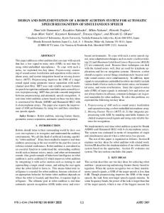
3. Design and System Integration The typical environment of an exhibit, which is highly dynamic, and the visitor experience expected with such a robot impose various constraints on the design and control. This leads to a specification of the mobile platform that can be summarized as follows: • Highly reliable and fully autonomous navigation in unmodified human-environments crowded with hundreds of humans. • Bidirectional multi-modal interaction based on speech (English, German, French and Italian), facial expressions and face tracking, icons (LED matrix), input buttons and robot motion. • Safety for humans, objects and the robot itself at all time. • Minimal human intervention and simple supervision. The esthetic of the robot has been designed in collaboration with artists, industrial designers and scenographers. The result of the design of both hardware and software is RoboX: a mobile robot platform ready for the real world (figure 1). Given the above mentioned specifications the mechanical, electronic and software design are now presented. a)
Face tracking Led matrix Eye movements
b)
Speech out (Speakers) Buttons Design Speech in (Microphone) Obst. avoidance Motion tracking Feat. extraction Localization Tactile sensors CompactPCI rack Bumpers
Figure 1: a) Functionality of the tour guide robot RoboX. b) An image of RoboX 9.
3.1 Mechanical Design The navigation base (lower part of the robot) consists mainly in the batteries, the CompactPCI rack with two control computers, the laser range sensors (two SICKs LMS200), the bumpers and the differential drive actuators with harmonic drives. The base (figure 2) has an octagonal shape with two actuated wheels on a central axis and two castor wheels. In order to guarantee good ground contact of the drive wheels, one of the castor wheels is mounted on a spring suspension. This gives an excellent manoeuvrability and stability to the 1.65 m height robot.
SICK sensor
CompactPCI rack Door chassis
Battery Door chassis Drive wheel
Castor wheel Suspension spring Motor
Batteries Castor wheel
Figure 2: Mechanical design of RoboX base. The upper part of the robot incorporates the interaction modules. The face includes two eyes with two independently actuated pan-tilt units and two mechanically coupled eyebrows. The left eye is equipped with a color camera, which is used for face tracking. The right eye integrates a LED matrix for displaying symbols and icons. The eyebrows further underline eyes expressions by means of a rotational movement. Behind the face, a gray scale camera pointing to the ceiling is mounted for localization purpose. The main input device for establishing a bidirectional communication with the humans are four buttons which allow the visitors to reply to questions the robot asked. The robot can further be equipped with a directional microphone matrix for speech recognition even though this remains very challenging in the very noisy environment of an exhibition.
3.2 Electronic Design The control system (figure 3) has been designed very carefully by keeping in mind that the safety of the humans and the robot has to be guaranteed at all time. It is composed of a CompactPCI rack containing an Intel Pentium III card and a Motorola PowerPC 750 card. The latter is connected by the PCI backplane to an analogue/digital I/O card, a Bt848based frame grabber, an encoder IP module and a high bandwidth RS-422 IP module. Furthermore a Microchip PIC processor is used as redundant security system for the PowerPC card (figure 3). The navigation software runs on the hard real-time operating system XO/2 [4] installed on the PowerPC. This processor has direct access to the camera looking at the ceiling, the two SICK sensors, the tactile plates and the main drive motors. It communicates with the interaction PC through Ethernet via an on-board hub. The interaction software is running under Windows 2000 on an industrial PC. This allows using commercial off-theshelf (COTS) software for speech synthesis and recognition, and makes scenario development easier. The PC has direct access to the eye camera, the eyes and eyebrows controller, the input buttons, the two loudspeakers and the microphone. The robot (both CPUs) is connected by a radio Ethernet to an external computer only for supervision, in order to track its status at any time on a graphical interface.
Robot Supervisor Desktop PC
HTTP wireless
Intel PIII 700MHz
Interaction Hardware
HTTP Motorola Navigation PPC750 Hardware 400MHz State Watchdog Bumpers Microchip PIC 20MHz Security action
Buttons Controller: This controls the main input device for the interaction between the robot and the humans. Four inductive buttons with different colors are used in combination to questions from the speech out to close the interaction loop with the robot. LED Matrix: The LED matrix is in the right eye. Its controller permit to show icons and animations. Eyes Controller: The eyes can be moved independently. The controller has a set of predefined expressions, which can be directly played. Face Tracking: The color camera in the left eye is used to track skin colored regions. The approach is based on [9]. This permits, in combination with the eyes controller, to track a face on the image and with the movement of the eyes.
Figure 3: Simple scheme of the electrical design
Navigation
3.3 Software Design
Odometry Driver: Calculates the position and uncertainty of the robot based on the wheels rotations.
As explained in the section above, the robot is composed of both an Intel Pentium and a Motorola PowerPC systems. The software has been firstly designed without taking into account this fact based on the functionality which was to be developed. However, as soon as the implementation started, the objects have been assigned to one of the two distributed systems. For hardware related objects (mainly sensor drivers) the choice was obvious. For the others, their relevance to safety has been evaluated: due to the hard real-time characteristics of XO/2, all the time-critical objects in relation with the security have been implemented on the PowerPC. Objects requiring COTS components have been implemented on the Windows machine because of their wider availability (f.e. MBrola for speech out, small FireWire camera in the eye for the face tracking, ...). The resulting object distribution is represented in figure 4. In the following part of this section each component of figure 4 is briefly presented starting with the interaction system followed by the navigation. A complete description of the interaction of RoboX can be found in [10]. Its navigation system is presented in [3].
Speed Controller: Regulates the speed defined by the obstacle avoidance with a PID controller accessing the encoders and updates the odometry. Localization: Uses a new approach [2] based on an Extended Kalman Filter [6] to correct the odometry with exteroceptive sensors (laser scanners, CCD camera). Obstacle Avoidance: Calculates a collision free path by initializing the path with a NF1 function [11] and using the Elastic Band approach [13] to dynamically adapt it. Furthermore it guarantees that the robot can stop before collision at any time with the Dynamic Window approach [7].
People Detection
PowerPC Interface
Scenario Controller
Speech Out
LED Matrix
Eyes Controller
PowerPC 750 - XO/2
Interaction Scenario Controller: It is the central object of the interaction subsystem, which accesses all the other objects. A scenario is a sequence of tasks from all modalities (speech, face expression, motion, LED matrix, etc.). A sophisticated tourguide scenario consists of several small scenarios which are played by the scenario controller. People detection: It permits to detect movements of objects around the robot by means of the laser scanners. By assuming a static environment, these moving objects are either humans or other robots. The moving objects are then tracked by means of a Kalman Filter. Speech Out: By using software permitting either text-tophonemes-to-speech or directly text-to-speech, this object permits the robot to talk in four languages (English, German, French and Italian). Furthermore files of format wav and mp3 can be played.
Buttons Controller
PIII - Windows 2000 Face Tracking
PC Interface
Global Planner
Multirobot Planner
Localization
Camera Driver
Security Controller
Obstacle Avoidance
Speed Controller
Laser Driver
Odometry Driver
Bumpers Driver
Figure 4: Object distribution of the software on the distributed embedded system.
Multirobot Planner: Synchronizes the movement of the robots to avoid to have many robots at the same place. Global Planner: Plans the navigation of the robot on the map level, by defining via points which permit to reach the goal point within the graph representing the map. Security Controller: Guarantees that the robot cannot become dangerous even in case of failure by supervising the safety-critical software and sensors. Due to the importance of this issue for a robot sharing the environment with humans, the next section presents the security system in details.
4. Security In this section the involvement of the security issue in the design of the whole system is pointed out in more details. All the software which relates to the movement of the robot is defined as safety critical. In order to guarantee the security of both the users and the robot itself, safety is on three levels: the operating system, the software implementation and the redundancy of the hardware.
4.1 Operating System All navigation software is implemented on the PowerPC which is operated by XO/2, a deadline driven hard real-time operating system [4]. Due to its characteristics XO/2 guarantees: • Safety: nothing bad happens. • Progress: the right thing do (eventually) happen. • Security: things happens under proper supervision. Static safety is guaranteed by the strong-typing characteristic of Oberon-2, the language used under XO/2. Many errors are already found at compile-time instead of run-time. Furthermore, index-checks, dynamic type systems and especially the real-time compatible garbage collector guarantee dynamic safety by forbidding almost any memory-management related errors. The deadline driven scheduler is in charge of progress: it guarantees that each task is executed within the predefined deadline. Of course this is possible only if the constellation of the tasks running on the PowerPC requires less than 100% of CPU. For this, the duration of each tasks has to be known. Admission tests are performed at each installation of a new real-time task to guarantee their feasibility. As soon as the progress of all real-time tasks is guaranteed, the CPU is scheduled between the non-real-time tasks depending on their priorities. Each error causes a system trap which is under complete control of the operating system. The system knows exactly where the error toke place (which line in the code), who called this part of the code up to the task currently running. This is very helpful for debugging, but it is even more important for security because for each task an exception handler can be defined. The actions which have to take place in such a case can therefore be properly defined.
4.2 Software Security Tasks whose failure could cause injuries to objects or peo-
ple required a special attention during design. Software watchdogs are therefore implemented for the speed controller, the obstacle avoidance and the bumpers driver (figure 4). Failure of one of these tasks is detected by the security controller which then either restarts the failed task or stops the robot and sends an e-mail to the maintenance. This permit to centralize the control of the security and to ask to a single object if a defect is disturbing the system. Furthermore the security controller generates a watchdog signal on a digital output permitting to know if both the operating system and the security controller are still running.
4.3 Hardware Redundancy The above mentioned software permits to have a consistent control system running on the PowerPC. However, this isn’t enough to guarantee the security of the robot and its neighborhood. Even in case of failure of the electronics or problems on the operating system of the PowerPC the robot must remain un-dangerous. For this the robot has a third processor: a Microchip PIC (figure 3). The software running on it checks the watchdog generated by the security controller, awaits acknowledgements from the security for each bumper contact and controls that the pre-defined maximal speed is never exceeded. If one of these conditions is not respected the redundant security software running on the PIC safely stops the whole system and set it in emergency mode (acoustic alarm).
5. Experiments At the time of writing 64 days of operation, from May 14 to July 17, are available for statistics. Each day from six to ten freely navigating tour-guide robots have given tours for 10.5 hours, from 9:30am to 8:00pm, on the surface of the exhibit which is approximately 320 m2.
5.1 Definitions Failure: A failure is any kind of problem which required a human intervention. The only exception is for the emergency button, which can be pressed and released also by visitors, and, due to logging difficulties, for situations where the robot remains blocked somewhere because it is to near to an object. In the latter case the staff can displace the robot by a switch which de-connects the motors from the amplifiers and allows to move the 115 kilograms robot easily. Uncritical: Uncritical failures are those which does not stop the task of the robot. For example, a failure consisting in a robot which stops sending an image to the supervisor is not critical for the tour the robot is giving to the visitors. Critical: Critical failures stop the robot until the human intervention is performed. An example is the failure of the scenario controller or of the obstacle avoidance. Reboot: Critical failures requiring a reboot of either the Pentium or the PowerPC are treated separately only because they require more time before operation.
5.2 Results After 64 days of operation the robots served more than 283’000 visitors for a total of 5’290 hours of operation. In order to do this job, they travelled more than 1’250 kilometers for a total moving time of more than 3’730 hours meaning that the mean displacement speed is 0.094 meters per second. As it can be seen in table 1, the uncritical failures represent only a small portion of the total amount of failures (10.9%). Furthermore they do not disturb the operation of the robot. They are therefore not treated in the following analysis which will focus on the critical and reboot failures of the whole robot first and then of the PowrePC.
Table 1: Two months of operation. After more than 5’000 hours of operation the RoboXes have travelled more than 1’250 kilometers and served more than 280’000 visitors. As it can be seen in figure 5, the beginning of the exposition in the middle of May showed that some work was still to be done. The software running on the PC was very unstable due especially to some errors in treating the list of the tasks running into the scenario controller. The mean time between failure (MTBF) of the whole robot (PC, PowerPC and hardware) during the first week was less than one hour (figure 6). This has been improved and is now around seven hours, which means that during one day with 10 robots, the staff has to perform a total number of interventions which is between 10 and 20. The type of interventions goes from the simple double-click to restart an application (typical intervention on the PC) to the change of an motor amplifier (very rare, it happened four times until now, two of them due to a motor defect). After the first three weeks, the
Figure 6: The mean time between critical failure of any kind (PC, PowerPC, hardware). The improvement has been constant exponential during the first four weeks, where the most important errors have been found. The current errors, which are rare, are more difficult to find. MTBF already doubled. Some errors were found after some weeks of operation, some other come for the first time after one month. The chance of having thousands hours of operation permits to improve the software and hardware to a level which is simply un-achievable with smaller projects. Another interesting chart is in figure 7, where all the critical failures coming from the navigation software (PowerPC) are shown. During the first three weeks, errors in the safetycritical tasks were treated by the security controller, but could sometimes require a reboot in order to restart the trapped task. This has been partly corrected allowing for much faster intervention in case of failure. Critical failures in figure 7 contains also error which have nothing to do with the implementation. For example, failures of the localization system are sometimes requiring human intervention. The peak of 17 critical failures on day 50 in figure 7 is due to a new person in the staff, which handled the robots without using the switch permitting to de-connect the motors from the amplifiers. This caused huge errors in the odometry and therefore some failures of the localization system. This is also the cause of the loss of MTBF of the robot between day 43 and day 57 in the chart of figure 6.
Figure 5: Due to many delays in the development, the software was still in the test phase at the beginning of the exposition. The first four weeks represent a huge improvement in the stability of the software, especially on the PC side.
Figure 7: The critical failures of the PowerPC (navigation system). Some of the critical errors require the reboot of the PowerPC. The peak of day 50 is due to bad manipulations of the robot by an untrained member of the staff.
Run time Movement time Travelled distance Average speed Failures (total / critical / uncritical) Critical failures (PC / PPC / HW) Visitors
5’293 h 3’736 h 1’259 km 0.09 m/s 2’097 / 1’869 / 228 1’641 / 163 / 65 283’319
The MTBF for the PowerPC (figure 8) was already at the beginning of the exposition at another level with respect to the rest of the software with values of 20 hours after one week and between 50 and 60 in the last two weeks. Without the day 50 problem the MTBF would be over 50 hours since around day 40. This better result is due to the characteristics of the XO/2 operating system which has been developed for embedded systems focusing on the robustness and safety, and due to the navigation software which is evolving since more than four years at the Autonomous Systems Lab in contrast to the interaction software which has been developed only for this application starting in late year 2000. Figure 9: Hardware problems also cause critical failures. Four motor amplifiers have had some problems. The block of errors between day 33 and day 40 is due to a very-goodweather week with temperature up to 35° in the exhibit. [3]
Figure 8: The MTBF during the first week was of about 20 hours. By neglecting the problem encountered during day 50, the MTBF would be over 50 hours starting from day 40.
[4]
Hardware failures (figure 9) are due to some uncritical design errors at the beginning (design of doors), to some motor-amplifier problems and to the temperature which was up to 35° in the exhibit between day 33 and day 40 (the SICKs do not like this!). This also showed a lack of the security approach, which did not take into account a possible failure of the laser scanners. When this occurred the obstacle avoidance continued to receive the last available scan from the driver causing a collision to the next object.
[5]
6. Conclusions and Outlook This project represents a milestone in the field of mobile robotics: for the first time tour-guide robots are produced (11 robots) and used for long time (five months) as real products instead of prototypes as in former projects. The paper presents their characteristics first, then goes into details about the mechanical, electrical and software design. The security issue is faced seriously for ensuring security of the humans and the robot itself all the time. In the experiments section the results of the first 64 days of operation of the Robotics exposition are presented and analyzed focusing on the amount and type of failures which occurred to the robots. References [1]
[2]
Arras, K. O., N. Tomatis, B. Jensen, and R. Siegwart (2001). "Multisensor On-the-Fly Localization: Precision and Reliability for Applications." Robotics and Autonomous Systems 34(2-3): 131-143. Arras, K. O., J. A. Castellanos, and R. Siegwart (2002). Feature-Based Multi-Hypothesis Localization and Tracking for Mobile Robots Using Geometric Constraints. IEEE Interna-
[6]
[7] [8] [9]
[10]
[11] [12] [13] [14] [15]
tional Conference on Robotics and Automation, Washington DC, USA. Arras, K. O., R. Philippsen, M. De Battista, M. Schilt, and R. Siegwart (2002). A Navigation Framework for Multiple Mobile Robots and its Application at the Expo.02 Exhibition. Workshop on Robots in Exhibitions, IEEE/RSJ International Conference on Intelligent Robots and Systems, Lausanne, Switzerland. Brega, R., N. Tomatis, K. Arras, and R. Siegwart (2000). The Need for Autonomy and Real-Time in Mobile Robotics: A Case Study of XO/2 and Pygmalion. IEEE/RSJ International Conference on Intelligent Robots and Systems, Takamatsu, Japan. Burgard, W., A. B. Cremers, et al. (1999). "Experiences with a Interactive Museum Tour-Guide Robot." Artificial Intelligence 00(1999): 1-53. Crowley, J. L. (1989). World Modeling and Position Estimation for a Mobile Robot Using Ultrasonic Ranging. IEEE International Conference on Robotics and Automation, Scottsdale, AZ. Fox, D., W. Burgard, et al. (1997). "The Dynamic Window Approach to Collision Avoidance." IEEE Robotics & Automation Magazine: 23-33. Graf, B., R. D. Schraft, et al. (2000). A Mobile Robot Platform for Assistance and Entertaiment. International Symposium on Robotics, Montreal, Canada. Hilti, A., I. Nourbakhsh, B. Jensen, and R. Siegwart (2001). Narrative-level Visual Interpretation of Human Motion for Human-robot Interaction. IEEE/RSJ International Conference on Intelligent Robots and Systems, Maui, Hawaii. Jensen, B., G. Froidevaux, X. Greppin, A. Lorotte, L. Mayor, M. Meisser, G. Ramel and R. Siegwart (2002). Visitor Flow Management using Human-Robot Interaction at Expo.02. Workshop on Robots in Exhibitions, IEEE/RSJ International Conference on Intelligent Robots and Systems, Lausanne, Switzerland. Latombe, J.-C. (1991). Robot motion planning. Dordrecht, Netherlands, Kluwer Academic Publishers. Nourbakhsh, I., J. Bodenage, et al. (1999). "An Effective Mobile Robot Educator with a Full-Time Job." Artificial Intelligence 114(1-2): 95-124. Quinlan, S. and O. Khatib (1993). Elastic bands: connecting path planning and control. IEEE International Conference on Robotics and Automation. Thrun, S., M. Beetz, et al. (2000). "Probabilistic Algorithms and the Interactive Museum Tour-Guide Robot Minerva." International Journal of Robotics Research 19(11): 972-99. Willeke, T., C. Kunz, et al. (2001). The History of the Mobot Museum Robot Series: An Evolutionary Study. Florida Artificial Intelligence Research Society (FLAIRS), Florida.