DESIGN AND TESTING OF A LOW-COST FLIGHT CONTROL AND DATA ACQUISITION SYSTEM FOR UNSTABLE SUBSCALE AIRCRAFT Alejandro Sobron , David Lundström , Ingo Staack , Petter Krus Linköping University, Linköping, Sweden Keywords: subscale, flight testing, flight control, data acquisition, relaxed stability
Abstract Current research on subscale flight testing methodologies at Linköping University is performed by using various platforms, some of them with advanced configurations. These have been previously flown in open-loop under direct commands from the pilot. However, the interest in flying some of these platforms with relaxed stability and the investigation of multi-surface control allocation techniques motivated the implementation of a simple low-cost flight control system based on commercial-off-the-shelf components. The work described in this paper evaluates the simplest available solutions that provide control augmentation for small, longitudinally unstable, free-flying models. This work also tries to define a reliable, fail-safe system architecture that can be implemented in more advanced platforms. Moreover, data acquisition and analysis are evaluated with the aim of applying system identification techniques. 1
Introduction
Testing physical subscale models has always constituted a valuable tool in aircraft development. Despite recent advances of modern computational techniques, wind tunnel testing still constitutes the backbone of aircraft design and aerodynamic research. However, free-flying subscale models have proved an excellent complement, and in some cases a lower-cost alternative to these techniques. This is especially interesting for high-risk conditions and for evaluation of unconventional designs for which no previous expe-
rience and simulation models exist; see for example NASA’s experiences summarised by Chambers in [1]. The miniaturisation of complex mechatronic systems and the development of rapid prototyping technologies have lowered significantly the cost and the manufacturing time of small and mid-size remotely-piloted aircraft systems (RPAS). Further, miniaturised electronics allow to obtain precise quantitative measurements of the aircraft properties, in addition to the usual qualitative assessment. These new possibilities make subscale flight testing an attractive evaluation tool to be integrated in the design loop during the initial phases of full-scale aircraft development. It has also become affordable for academic institutions where it additionally serves as an extraordinary practical training for students [2]. Current research on subscale flight testing methodologies at Linköping University (LiU) is performed by using various platforms, some of which feature advanced configurations such as the Generic Future Fighter (GFF) subscale demonstrator, described in [3] and shown in Fig.1. Although equipped with data acquisition systems [4], these platforms have been previously flown in open-loop in stable configurations. However, the interest in flying some of them with the relaxed stability configuration they were originally designed for, as well as the possible investigation of multi-surface control allocation techniques, motivated the implementation of a simple, low-cost flight control system (FCS) [5].
1
SOBRON A, LUNDSTRÖM D, STAACK I, KRUS P
The work presented here tries to evaluate the simplest available commercial off-the-shelf (COTS) solutions that can provide control augmentation even for the high-frequency, shortperiod dynamics of small free-flying models often used in student projects, Fig.2. Autonomous navigation capabilities are disregarded. This work also tries to define a reliable, fail-safe system architecture to be implemented on the more advanced platforms. Furthermore, integrated data acquisition possibilities are evaluated with the aim of analysing the aircraft characteristics and applying system identification techniques.
data and upload direct control surface commands, such as the system used by NASA in [6]. However, this system relies upon a solid data transmission link with low latency which would be difficult to achieve with a limited budget. Therefore, a FCS onboard the aircraft, following the concept sketched in Fig.3 is preferred despite eventual limitations in processing power. Sensors
Reception Signal modulation
FCS Signal mixing Control Laws
Stability and Control Augmentation System feedback
Signal processing and digital modulation Control stick
Transmission
Servomechanism
Control surface
Visual feedback
Fig. 3 . Concept diagram of a RPAS with a FCS onboard.
Fig. 1 . GFF subscale research platform, described in [3].
Fig. 2 . Some of the small test-bed models used for experimental verification of equipment and procedures.
2
Frame of Reference
The aim is to integrate COTS solutions where possible rather than developing a new system from scratch. Disregarding autonomous flight functions of the so called “autopilots”, there are currently different solutions that provide augmented flight control to small RPAS. Groundbased FCS solutions process downloaded sensor
A basic stability augmentation system (SAS) can be achieved by using relatively simple and inexpensive equipment only: angular rate closedloop controllers based on single-axis gyroscope sensors. These are extensively used in the radiocontrolled (R/C) market to stabilize the directional axis (tail rotor pitch) of R/C helicopters. Applied on aeroplanes, the authors have previous experience using the MEMS gyroscope Futaba GYA352 [7] to stabilize roll and pitch in one of the jet-powered research platforms. However, only vague examples of its use in highly unstable configurations were found. Although this solution would require an external data logger, it was decided to explore further this concept for its possible use as a back-up system. Regarding more advanced control, Cai et al. present in [8] a thorough review of FCS used in different kinds of UAVs. According to these authors, PC/104 embedded computers are widely used in mid-size platforms such as in [9]. However both cost and form factor are still excessive for this application. Dantsker et al. [10] offer a comprehensive review of several FCS with small form factor that also log and process sensor data, both closed-source and open-source COTS products as well as custom-made avionic systems such as the one developed by Beard et al. [11]. Open-source solutions are favoured not only for cost reasons, but also for flexibility of 2
DESIGN AND TESTING OF A LOW-COST FLIGHT CONTROL AND DATA ACQUISITION SYSTEM FOR UNSTABLE SUBSCALE AIRCRAFT
development. For example, the platform Ardupilot Mega has been used as a base for similar projects such as in Hartley et al. [12] and in Arifianto and Farhood [13]. Nevertheless, among the current options two platforms based on 32 bit microprocessors with sensor data processing and logging capabilities stood out because of their promising performance and connectivity: Paparazzi firmware combined with Apogee v1.00 hardware [14], and PX4/APM firmware combined with Pixhawk hardware [15]. The Pixhawk, a project started by the Computer Vision and Geometry Lab in ETH Zürich, supported by the Linux Foundation Dronecode community and the private company 3D Robotics, was finally selected for further investigations. Besides an embedded NuttX realtime operating system (RTOS) and a specifically developed PX4 middleware layer, the user can choose the flight control firmware to be run on top: PX4 autopilot from the same authors, or the well-known APM multiplatform autopilot, both open-source too. Due to the larger developers community and better documentation, the fixedwing version of the APM firmware, known as APM-Plane [16] was chosen here as a starting point for further development. Despite of the already notable capabilities of these high-end hobbyist autopilot systems, in the opinion of the authors it is expected that future developments will be increasingly based on standardised real-time Linux-based platforms, such as Navio2 and Raspberry Pi [17]. 3
System Design
The aim is to assemble a compact, modular system that could be exchangeable between different test-bed platforms. Critical requirements were minimum physical size, weight, and power consumption for the main flight controller as well as the sensors and connected peripherals. In addition, a fail-safe design needed to be considered: even if the FCS can switch to direct manual control in case of system failure, the pilot would not be able to control an unstable aircraft. Therefore, some alternative must be provided, and only two possibilities exist: modifying the static margin
in flight, or engaging a secondary SAS. The first option implies either moving the centre of gravity forward using a weight shifting mechanism or moving the neutral point backwards, which in the canard-delta configuration can be done by aligning the canards with the airflow. A weight shifting mechanism with sufficient effect on the balance was considered difficult to integrate, similarly to some mechanism for freeing and reattaching the canards in place. Using direct information from an angle of attack (AOA) vane sensor to command the canards would still require functional sensor data processing. Instead, an alternative force-sensing control law for the servo actuators was conceived and investigated: an R/C servo was modified and analysed in a test rig, but results were not satisfactory due to complicated sensitivity adjustment and excessive hysteresis effects. For these reasons, the option of placing an auxiliary R/C MEMS gyroscope controller providing a basic SAS was further investigated using small electric-powered test-bed aircraft both in delta-canard and conventional configurations as in the example shown in Fig.4. MEMS gyro sensor
GY
Variable CG position
High-speed servo actuator
Fig. 4 . A MEMS gyroscope sensor was installed in a Multiplex FunCub model in order to test a basic longitudinal SAS approach with negative static margin.
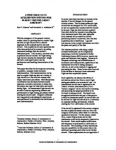
Some remarkable characteristics of the selected hardware, the Pixhawk controller [15], are its good connectivity and the integrated capability of logging sensor data at acceptable sampling rates, as shown in Fig.5. The APM-Plane firmware code was modified in order to increase the logging rate of some variables of interest, such as the pilot commands. However, the logging performance is still limited and any further increase in sampling rates would be better managed with an external data logger device. 3
SOBRON A, LUNDSTRÖM D, STAACK I, KRUS P INPUTS Accelerometers Gyroscopes Magnetometer Barometer Alpha Beta vanes Airspeed sensor GPS module Pilot commands
PROCESSING
LOGGER
1000+ Hz 1000+ Hz 130 Hz 130 Hz
5 Hz
P
50 Hz Main Processor STM32F427 32 bit, 168 MHz
50+ Hz 10+ Hz
P
50 Hz
A B
50 Hz
E
10 Hz 10 Hz 50 Hz
Safety Processor STM32F103 32 bit, 72 MHz
M
A
F
Data Logger Micro SD Card
L
R
S
T
10 Hz C
5 Hz
G
O
50 Hz
L
telemetry
controls
controls
controls
... S
S
S
Y
OUTPUTS
UART
I2C bus
CAN bus
PWM
F
G
Fig. 5 . Main I/O of the FCS and respective sampling/logging rates after modification of the APM-Plane firmware. Adapted from an original diagram by the PX4 developers community [15].
E
M
T
S
R
A
Alpha vane
B
Beta vane
C
Camera
E
Voltage + current sensor
F
Flight controller (+ 2xIMU + baro.)
G
GPS module + magnetometer
L
Dedicated LiPo battery
M Motor O OSD + video recorder
3.1
Instrumentation
The sensors already in-built in the Pixhawk board are inexpensive and not certified for professional flight testing, but have proved robust in harsh environments with vibration and large temperature variations such as those usually found in hobbyist-type operations. The main board comprises two different inertial measurement units (IMU) with an integrated magnetometer ([18], [19] and [20]), and a barometric pressure sensor [21]. Additional external sensors can be integrated to complete the desired FCS architecture, as the example shown in Fig.6. The most relevant peripheral components are discussed below. 3.1.1 Airspeed sensor Previous experiences with analogue pressure transducers from other hobbyist-type systems showed that these suffer severe variance with temperature. Here, inexpensive COTS pressure transducers with digital output and temperature compensation 3D Robotics are used. Since an appropriate wind tunnel was not available, calibration was done in flight as explained in [5]. 3.1.2 Airdata boom Various airdata booms were built in-house combining a pitot-static probe with flow-direction transducers. Fig.7 shows the integration of the pitot-static probe with a 3D-printed AOA
P
Pitot tube + Termometer
R
Radio link receiver
S
Servo
T
Telemetry modem
Y
Auxiliar gyroscope sensor
Fig. 6 . Layout of the proposed FCS and its main sensors in the GFF platform and one of the smaller test-bed models.
vane in the lightest airdata boom used in the small test-bed aircraft. A larger boom is shown in Fig.8. Angles are measured using magnetic-induction rotary encoders extracted from inexpensive hobbyist-type R/C servos HK28013DMG. The angular position is computed by measuring the linear analogue output of the encoders through two of the available ADC ports on the Pixhawk board. 3.1.3 GPS and external magnetometer Electromagnetic noise caused by onboard equipment can disturb sensible sensors and receiver antennas, as measured by Dantsker et al. [10]. It is desirable to place a remote GPS antenna and a secondary magnetometer as far as possible from the main electric devices. In this case, the recommended low-cost COTS module manufactured by 3D Robotics was used. It integrates a U-blox GPS module [22] and a digital magnetometer [23] in a small and light package.
4
DESIGN AND TESTING OF A LOW-COST FLIGHT CONTROL AND DATA ACQUISITION SYSTEM FOR UNSTABLE SUBSCALE AIRCRAFT
4
Fig. 7 . CAD model of the small airdata probe (8 mm of diameter) combining a pitot-static tube and a flow-direction transducer. The sensor housing, the vane arm, and the vane were 3D-printed in ABS plastic.
Modelling and Simulation
A simulation model is the base for evaluating the flight dynamics of the flying platforms as well as the effect of control laws, control loop tuning, and later on for the application of system identification techniques. Following a statespace approach, two levels of complexity are defined: a simplified, approximated linear model of the small test-bed aircraft and a more exhaustive non-linear model of the research platforms. The latter is not only based on theoretical and numerical analyses, but also on experimental data such as wind tunnel tests. It is still under development at the time of writing this paper. 4.0.1 Mass and inertia properties Given the size of the aircraft it is easy to measure accurately the total mass and that of the components onboard. The inertia properties of the research platforms was measured experimentally using the pendulum motion technique [24]. However, due to the difficulties of doing this on the very light airframes, the inertia properties of these aircraft were estimated using a MATLAB script based on CAD airframe data and discrete point loads, Fig.9.
Fig. 8 . Larger airdata nose-boom with alpha and beta transducers installed in the GFF platform.
3.1.4 Voltage and current sensor Power sensors typically measure the main and radio battery levels in hobbyist rigs. Here this setup is only used in the smaller electric-powered test-bed aircraft. On the jet powered platforms, it monitors the fuel pump activity in order to measure the fuel consumption. 3.1.5 Video camera and OSD Light micro-cameras, with or without on-screendisplay (OSD), capture phenomena of interest such as the performance of the flow-angle transducers (Fig.11) or the attitude of the aircraft in reference to the horizon.
Fig. 9 . One of the lightweight test-bed aircraft modelled in the MATLAB script developed to estimate numerically the inertia properties.
4.0.2 Aerodynamic model Preliminary aerodynamic coefficients were estimated using the vortex lattice method (VLM) Tornado [25]. A traditional drag bookkeeping method supported by CAD wetted area computation was used to estimate the parasite drag. A 5
SOBRON A, LUNDSTRÖM D, STAACK I, KRUS P
first estimation of the neutral point location was obtained from the VLM computation, although this was later verified and refined through flight testing. Propeller effects were disregarded. 4.0.3 Servo actuators The servo actuator model is particularly important. One of the main problems with the integrated data acquisition system is that it lacks sufficient analogue inputs to measure the real control surfaces deflection. Therefore the actual deflection has to be estimated from the commanded pulse-width modulated signal using an accurate model of each servo. The dynamics are assumed to be a second order, critically damped system with rate limit [12]. By experiment, the maximum rate and bandwidth for every servo were measured by comparison of a sinusoidal input reference signal with the servo arm position in a simple test-rig. 4.0.4 FCS Gaussian noise is added to the sensor measurements, but no further errors or bias. Except for the nose-boom, no dynamic effects are introduced since the short distances to the centre of gravity can be neglected. Alpha and beta measurements are corrected with the appropriate response equations taking into account the fast angular motions of the aircraft. The control laws of the gyroscope controller and those available by default in the APM-Plane [16] firmware were interpreted from the code and modelled accordingly. These are simple PID control loops with an airspeed scaling factor, available for both pitch/roll attitude and angular rate, as in the example Fig.10. Airspeed Scaler
V Vref
kP . θref = qref
+
-
Amp.
+
-
Scaler X
kI
kD
+
+ +
Scaler X
ec
Servo
δE
.
Aircraft θ = q Dynamics
Int. 1 s IMU rate
Fig. 10 . Structure of the pitch rate control law of the APMPlane firmware, version 3.2.1.
4.0.5 Engine Model The propulsion model is especially relevant for the longitudinal motion dynamics. In small electric motors, dynamics such as spool up time are negligible compared to the rigid body dynamics [12]. However, this is taken into account in the jet engines by means of a delay roughly based on observations. If existing, moments due to misalignment are taken into account, but the effects of the propeller are disregarded. Static thrust was measured directly, but the effects of airspeed are modelled according to traditional equations found in literature. 5
Initial Flight Testing
An initial flight test campaign was focused on calibrating the different sensors and verifying their consistency and robustness. Figures 11 and 12 illustrate part of this process with the airdata boom installed in the small test-bed aircraft.
Fig. 11 . Evaluation of the small AOA transducer performance and calibration by comparing logged flight data with visual references captured by a micro-camera.
Previous unsatisfactory experiences with a high-end attitude and heading reference systems (AHRS) onboard small subscale aircraft showed that a capable and robust algorithm is essential for accurate attitude estimation in this environment of high g-forces and rapid motions. The APM-Plane firmware, from version 3.5 onwards, runs in parallel two instances of an extended Kalman filter (EKF) taking advantage of two IMU data. The algorithm evaluates their condition in real time and selects the most consistent. To ensure robustness, a simpler direction-cosinematrix algorithm runs in the background and it 6
DESIGN AND TESTING OF A LOW-COST FLIGHT CONTROL AND DATA ACQUISITION SYSTEM FOR UNSTABLE SUBSCALE AIRCRAFT Raw data
Low−pass off−line filter, 2 Hz corner frequency
40 30
Power/Frequency (dB/Hz)
20 10 0 −10 −20 −30 −40 −50 −60
0
5
10 15 Frequency (Hz)
20
25
Fig. 12 . Power spectral density using fast Fourier transform, applied to the smallest AOA transducer to design an adequate filter.
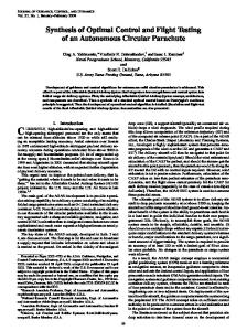
tuned while the static margin was gradually reduced. As an example of the effect of the static margin in the short period dynamics, Fig.14 shows the response to pitch angle step inputs of the Multiplex FunCub (4) model at different static margins with the same PID gains setting. Similar effects were observed with the pitch rate control law. Stability was recovered in most cases by increasing the derivative (D) gain. Negative static margins in excess of minus 20 percent were achieved successfully. Beyond this value, the response time of the pitch servos and the available elevator authority became the limiting factors. In some platforms, effects of lateral instability started to appear before reaching this point. Demanded pitch
Actual pitch
(a)
Angle [deg]
50 0 −50 50
(b)
Angle [deg]
is called if the two primary EKF fail. The consistency of the attitude and estimated trajectory were tested in continuous high-g turns and other aggressive manoeuvres using various platforms. As the example in Fig.13, test results suggest that the estimation is stable and fairly accurate.
0 −50
(c)
Angle [deg]
50 0 −50
0
5
10
15
20
25
30
35
40
Time [s]
Fig. 14 . Response to pitch angle step inputs of the Cub test-bed with pitch angle control engaged and the same PID gains setting, for: (a)8 percent of positive static stability margin, (b)neutral static stability, (c)10 percent of negative static stability.
Fig. 13 . One of the jet-powered platforms performing sustained high-g turns to test the robustness of the attitude estimation. Flight data are superimposed on real video using the open-source software Mission Planner [26].
5.1
Tests with Relaxed Stability
The FCS was tested under relaxed stability configurations using the small test-bed aircraft. Although simulations gave an initial guess of the controller gains, the system was experimentally
The single-axis gyroscope controller approach was tested with an inexpensive hobbyisttype gyroscope Assan GA250, using both rate and angle-hold control laws. Results were surprisingly similar, although the lack of variable gains according to airspeed makes the tuning process more critical. In addition, since the gyroscope reacts equally to any angular velocity about the pitch axis, banked turns become excessively damped. However, similar values of negative static margin were achieved with this solution and the same limiting factors were detected.
7
SOBRON A, LUNDSTRÖM D, STAACK I, KRUS P
5.2
Assessment of Manual Control
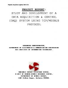
The small test-bed aircraft were also used to assess qualitatively the limits of manual control with the FCS disengaged. The observations suggest that the degradation of the flying qualities is highly airframe-dependent, and other factors such as wind speed and turbulence also affect the outcome. Most platforms could be flown manually up to the neutral static stability margin, where they present significantly degraded flying qualities that could be rated as level 8-9 in the Cooper-Harper scale [27]. It was possible to continue further into negative static margins with certain platforms. However, assuming an average skilled pilot, results suggest that it is not advisable to go beyond minus five percent in any of the cases, see Fig.15.
Angle [deg]
200
30
150
20
100
10
50 0
0
−1
250
40
]
Angle of attack, α
Angular rate [deg s
Pitch angle, θ
Pitch rate, q 50
−10
−50
−20
−100
−30
−50
−150
FCS disengaged
−40 0
2
−200 4
6
Time [s]
8
10
12
14
−250
in case of a FCS failure. Flight tests have proved that a simple single-axis gyroscope controller is a valid and inexpensive solution. The proposed setup also works as a data acquisition system. Appropriate filters have been designed and the original firmware has been modified to increase the sample rate of some parameters. Accurate trajectory reconstruction (Fig.16) is easily obtained, and attitude estimation seems robust and consistent according to the test results. A MATLAB script has been developed in order to display, analyse and pre-process the flighttest data for application of system identification tools. The complete simulation model of the GFF research platform is currently under development and due to time limitations, system identification results could not be included in this publication. However, the data obtained already offer a preliminary quantitative assessment of the flight characteristics of the GFF platform, as in the example shown in Fig.17 for a high angle of attack manoeuvre. However, to increase further data acquisition capabilities it is proposed to complement the FCS with a standalone computer or a dedicated data logger.
Fig. 15 . Uncontrollable attitude oscillations occur when trying to control manually the Cub model with a negative static margin of -10 percent, with the FCS disengaged.
6
Discussion
The presented low-cost FCS architecture is based primarily on a COTS system, which apart from the flight controller, integrates a sensor data logger. Different control laws have been flight-tested under relaxed stability conditions in diverse small test-bed aircraft with successful results. Observations suggest that the main limiting factors for the effective control of highly unstable platforms are the delay of the pitch servo actuators and the authority of the pitch control surfaces at low speeds. The system has also been evaluated in open-loop setup on the larger jet-powered platforms. The observed difficulties to maintain manual control under relaxed stability settings suggest that it is critical to incorporate a secondary SAS
Fig. 16 . Trajectory reconstruction of a flight test exported into Google Earth using the open-source software Mission Planner [26].
7
Conclusion
The system presented here is a valid low-cost solution for flight control of subscale platforms 8
DESIGN AND TESTING OF A LOW-COST FLIGHT CONTROL AND DATA ACQUISITION SYSTEM FOR UNSTABLE SUBSCALE AIRCRAFT True airspeed
Vertical speed
AOA, α
Pitch, θ
60 50
Angle [deg] Velocity [m s -1 ]
40 30 20 10 0 -10 -20
0
5
10
15
Time [s]
20
25
30
Fig. 17 . High angle of attack manoeuvre performed by the GFF research platform.
with relaxed stability. Its modular architecture based almost entirely on open-source COTS components requires a minimum development time and allows any desired modifications. Both the primary FCS and the backup system have been tested in different small test-bed aircraft and their satisfactory performance seems only limited by the control surface actuation. As a data acquisition system, it provides data of sufficient quality to allow identification of flight dynamical characteristics. Specific software tools have been developed to visualise and pre-process the flight-data for further analysis, but at the time of writing this paper the complete simulation models and the system identification tools are still under development. References [1] Chambers J R. Modeling Flight: The Role of Dynamically Scaled Free-Flight Models in Support of NASA’s Aerospace Programs. 1st ed. NASA, Washington, DC, USA, 2009. [2] Jouannet C, Berry P and Krus P. Aircraft Design Education at Linköpings University. Proceedings of the Institution of Mechanical Engineers, Part G: Journal of Aerospace Engineering, vol. 221, pp. 217–224. 2007. [3] Amadori K, Jouannet C and Berry P. Development of a subscale flight testing platform for a generic future fighter. 27th Congress of International Council of the Aeronautical Sciences. Nice, France, 2010.
[4] Staack I and Lundström D. Subscale Flight Testing at Linköping University. 27th Congress of International Council of the Aeronautical Sciences. Nice, France, 2010. [5] Sobron A. Design and Testing of a Flight Control System for Unstable Subscale Aircraft. Master’s thesis, Linköping University, 2015. [6] Jordan T L, Foster J V, Bailey R M and Belcastro C M. AirSTAR: A UAV Platform for Flight Dynamics and Control System Testing. 25th AIAA Aerodynamic Measurement Technology and Ground Testing Conference. American Institute of Aeronautics and Astronautics, San Fracisco, CA, USA, 2006. [7] Futaba. GYA352 MEMS Gyroscope, 2016. URL https://www.rc.futaba.co.jp/ english/gyro/airplane/gya352 [8] Cai G, Dias J and Seneviratne L. A Survey of Small-Scale Unmanned Aerial Vehicles: Recent Advances and Future Development Trends. Unmanned Systems, vol. 02, no. 02, pp. 175–199, 2014. [9] Jang J S and Tomlin C J. Design and Implementation of a Low Cost, Hierarchical and Modular Avionics Architecture for the DragonFly UAVs. AIAA Guidance, Navigation, and Control Conference and Exhibit, August, pp. 4465–4477. AIAA, Monterey, CA, USA, 2002. [10] Dantsker O D, Mancuso R, Selig M S and Caccamo M. High-Frequency Sensor Data Acquisition System (SDAC) for Flight Control and Aerodynamic Data Collection. 32nd AIAA Applied Aerodynamics Conference. AIAA, Atlanta, GA, USA, 2014. [11] Beard R W, Kingston D, Quigley M, Snyder D, Christiansen R, Johnson W, McLain T and Goodrich M. Autonomous Vehicle Technologies for Small Fixed-Wing UAVs. Journal of Aerospace Computing, Information, and Communication, vol. 2, no. 1, pp. 92–108, 2005. [12] Hartley R F, Hugon F D X, Anderson R and Moncayo H. Development and Flight Testing of a Model Based Autopilot Library for a Low Cost Unmanned Aerial System. AIAA Guidance, Navigation, and Control (GNC) Conference, pp. 1–25. AIAA, Boston, MA, USA, 2013. [13] Arifianto O and Farhood M. Development and Modeling of a Low-Cost Unmanned Aerial Ve-
9
SOBRON A, LUNDSTRÖM D, STAACK I, KRUS P
[14]
[15]
[16]
[17]
[18] [19] [20] [21]
[22] [23] [24]
[25]
[26]
[27]
hicle Research Platform. Journal of Intelligent & Robotic Systems, vol. 80, no. 1, pp. 139–164, 2015. École nationale de l’aviation civile and Paparazzi develpers community. Paparazzi project, open-source autopilot system, 2015. URL http://wiki.paparazziuav.org/ Computer Vision and Geometry Lab at ETH Zürich 3D Robotics Inc and PX4 developers community. PX4/Pixhawk open-hardware autopilot project, 2015. URL http://pixhawk.org/ Dronecode Project Inc a Linux Foundation Collaborative Project. APM:Plane open-source autopilot firmware, 2016. URL http://plane.ardupilot.com/ Emlid. Navio2 Linux autopilot, 2016. URL https://emlid.com/ introducing-navio2/ STMicroelectronics. LSM303D Three-axis MEMS accelerometer and magnetometer, 2013. STMicroelectronics. L3GD20 Three-axis MEMS digital gyroscope, 2013. InvenSense. MPU-6000 Six-axis MEMS motion tracking device, 2013. Measurement Specialities. MS5611 Barometric pressure sensor. Measurement Specialties, 2012. U-blox. NEO-7 GPS/GNSS module, 2014. Honeywell. HMC5883L Three-axis digital magnetometer, 2013. Jordan T, Langford W and Hill J. Airborne Subscale Transport Aircraft Research Testbed - Aircraft Model Development. AIAA Guidance, Navigation, and Control Conference and Exhibit. American Institute of Aeronautics and Astronautics, San Fracisco, CA, USA, 2005. Melin T. Tornado, the Vortex Lattice Method, Version 135, 2010. URL http://www.redhammer.se/tornado/ Oborne M and Dronecode Project Inc. Mission Planner open-source ground station software, Version 1.3.37, 2016. URL http://ardupilot.org/planner/ Nelson R C. Flight stability and automatic control. 2nd ed. WCB/McGraw-Hill, Singapore, 1998.
Contact Author Email Address
[email protected]
Copyright Statement The authors confirm that they, and/or their company or organization, hold copyright on all of the original material included in this paper. The authors also confirm that they have obtained permission, from the copyright holder of any third party material included in this paper, to publish it as part of their paper. The authors confirm that they give permission, or have obtained permission from the copyright holder of this paper, for the publication and distribution of this paper as part of the ICAS proceedings or as individual off-prints from the proceedings.
10