PROC. IMECHE VOL. XXX PART M: J. ENGINEERING FOR THE MARITIME ENVIRONMENT
Design and Testing of an Innovative Cleaning Tool for Underwater Applications Hilal Tolasa Gundogdu1, Mehmet İsmet Can Dede2, Bariş Taner2, Alessandro Ridolfi3, Riccardo Costanzi3, Benedetto Allotta3
[email protected],
[email protected],
[email protected],
[email protected],
[email protected],
[email protected] 1
Nesne Elektronik Ltd. Sti., IZTEKGEB A1 Blok No:8 Urla, Izmir, Turkey
2
Department of Mechanical Engineering, Izmir Institute of Technology, Izmir, Turkey
3
Department of Industrial Engineering (DIEF), University of Florence, Florence, Italy
Abstract — The aim of this work is to describe the development of an innovative Cleaning Tool (CT) for underwater applications, to be used in particular in the field of underwater archaeology. This work takes place in the framework of the EU FP7 funded ARROWS project. ARROWS adapts and develops low-cost autonomous underwater vehicle technologies to significantly reduce the costs of underwater archaeological operations, covering the full extent of archaeological campaigns. The project deals with underwater mapping, diagnosis and cleaning tasks. During the first half of the project, a Cleaning Tool prototype, able to be mounted on underwater vehicles, has been worked out: this cleaning tool will be exploited not only during research missions, but also for the periodic monitoring, controlling and maintenance activities of well-known underwater archaeological sites (e.g. periodic cleaning operations). Keywords—Autonomous Underwater Vehicle, Underwater Robotics, Underwater Cultural Heritage, Underwater Intervention, Cleaning Tool.
I. INTRODUCTION The ARROWS project [1] [12] aim is to provide the underwater archaeologists with technological tools for cost-affordable campaigns. Several technologies, originally developed for military use and the Oil & Gas industry, have been successfully adapted to underwater archeology (e.g. acoustic communication or sub bottom profiling). However, there is still a strong motivation for archaeologists to reduce the costs associated with underwater campaigns, otherwise impossible to perform without the support of private sponsors and/or foundations. ARROWS project is funded by the European Commission in the framework of the FP7 call ENV-2012, challenge 6.2-6. The project is coordinated by the University of Florence (Italy) and its consortium is
composed of several research institutions and SME companies dealing with Underwater Robotics, coming from 5 different countries. The ARROWS Steering Board is supported by a purposely created Archaeological Advisory Group (AAG), composed of European archaeologists whose task is to guide and follow all the strategic developments of the project. ARROWS adapts and develops user-friendly autonomous underwater vehicle technologies to significantly reduce the cost of archaeological operations, covering the full extent of archaeological campaigns. The project deals with underwater mapping, diagnosis and cleaning tasks. In particular the presented paper deals with the development of an innovative Cleaning Tool (CT) for underwater applications. According to the archaeologists’ experience, a “cleaning device” has been considered, instead of an excavating one. The 2001 UNESCO Convention for the Protection of Underwater Cultural Heritage guidelines for the submarine findings plan to monitor the objects found without interacting with them in a mechanical way. For example, the objects found are left where they are, both for safety reasons and for economic ones (cost and low availability of storehouses on land). The excavation is not a practice to be used for Underwater Cultural Heritage (UCH). In addition, the excavating activity would probably damage the stratigraphy of the area causing a loss of very important data. The underwater archaeologists would instead benefit a lot from the availability of a cleaning tool integrated with an underwater robot system. It is worth to note that the cleaning tool will be exploited not only during research missions, but also for the periodic monitoring and controlling of well-known underwater archaeological sites (e.g. periodically cleaning operations or evaluation of the changes of a site). In order to softly clean the focus area, this cleaning device should blow air/water to dissolve the sand or mud on the archeological artifacts and also suck dissolved sand or mud to remove these from the focus area. Moreover, ARROWS is dealing with the development of a team of new heterogeneous Autonomous Underwater Vehicles (AUVs) [13] [14] to support archaeologists in all the phases (mapping, diagnosing, cleaning, and monitoring) of underwater campaigns. Three classes of new AUVs are developed according to archaeologists’ needs. The innovative AUVs, developed in the framework of ARROWS, are: • MARTA (MARine Tool for Archaeology) AUV: it is a modular AUV, easily adaptable to the various types of mission according to its configuration [15]; • U-CAT: small biomimetic (turtle-shaped) AUV exploiting fin-based propulsion, usable for shipwreck penetration; • A-sized AUV: small torpedo-shaped vehicle, easily manageable thanks to its reduced size.
Among these vehicles, A-sized AUV and MARTA can be equipped with the CT and the archaeologists will be trained to use the innovative tools produced in the framework of the ARROWS project. The system effectiveness will be demonstrated in two places, different as regards the environment and the historical context, the Mediterranean Sea (Egadi Islands) and the Baltic Sea. In this paper, the design process of the innovative cleaning tool is explained. Analysis results of the design are given to provide information about the optimization of the CT. Two prototypes were built to validate the design at two stages as intermediate design and final design. Experiments were conducted to evaluate the performance of the CT with respect to the design criteria set, which is explained in the next section. Finally, the experimental test results are obtained and discussed.
II. PRELIMINARY DESIGN OF THE CLEANING TOOL As anticipated, one of the main commitments of the ARROWS project was the development and the production of a prototype of an underwater cleaning tool to be integrated on one of the available AUVs to be used in ROV mode and to be capable of performing soft cleaning activities on wellknown archaeological artifacts needing maintenance. The common tools used for underwater cleaning activities can be classified into two main categories:
contact-based cleaning devices: those are devices based on the use of brushes, of different materials and configurations according to the particular application, moving on the surface to be cleaned for dirt removing, e.g. [7] [8] [9];
flow-based cleaning devices: those are devices based on the generation of high-pressure flows, that, oriented on the surface to be cleaned, are able to dissolve also hard dirt [11].
The particular application, within the ARROWS project, could not exploit none of the two common solutions; in fact, it is better not to perform mechanical cleaning activities on artifacts of archaeological relevance and the pressure of common flow-based cleaning devices may be too high and may damage the artifact itself. Moreover, the project aims at avoiding some commonly used manual cleaning operations [10]. The adopted solution, i.e. the developed device, within the ARROWS project favors the moved water quantity with respect to the pressure and exploits a secondary flow to move the dissolved dirt away from the
cleaning area. This secondary flow is inspired by the concept of the classical underwater dredges used from several years for excavation purposes by underwater archaeologists, e.g. [6]. During the initial meetings with the underwater archeologists within the ARROWS project, preliminary specifications of the CT were defined as:
operating depth at a maximum of 100 m;
mountable on the AUVs;
to be run in ROV (Remotely Operated Vehicle) mode to receive external power;
able to create water jets to dissolve the mud or dirt on the archaeological object and to suck the dissolved mud or dirt;
to be neutrally buoyant.
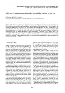
With respect to the criteria set above, an initial concept was derived. The details of the initial design are explained in the next sub-section. Initial Design of CT Initially, the idea was to blow water jets onto pile of dirt right from the middle of the operational head, which is composed of a nozzle and a duct. This way, water jets would dissolve mud on the archeological object into the sea water and then, through a suitable suction action, dissolved particles would be collected by the duct. As described in [2], suction is an appropriate method for collecting mud, and it reduces the chance of damaging artifacts beneath the pile of mud. Relying on that idea, some modifications, in particular to the nozzle and the duct, are issued as shown in Figure 1. The dark blue arrows show the water jet going through the nozzle to dissolve the mud while the light blue arrows indicate the direction of the sucking action to remove the dissolved mud with water from the sea floor.
Figure 1: Sketch of the general concept Conceptual design based on this idea is given in Figure 2. It is designed to have a pipeline attached next to the suction line or the pipeline can be supported with bars to be placed right in the middle of the suction line. Also, there is an active propeller or pump to generate a suction force in the suction line. In this design, there is a physical blockage in the suction line in front of the sucked particles due to the propeller and/or nozzle supply line. Particles in dissolved mud could vary in size and shape and eventually can build up along flow direction, which can reduce system performance or result in system failure. Another case is the suction of an archeological object within the mud. Finally, there should be two actuation systems to create the water jet and to activate the suction action for this design. In this case, the physical blockage can result in damaging the archeological object. According to these foreseen problems, the initial design had to be modified.
Figure 2: Concept with the suction-head The design is modified to carry out the suction action by the motive fluid. This way, there will be no parts within the suction line to create blockage and no unexpectedly sucked archeological objects will be damaged. This design modification is further explained in the next subsection. Working Scheme and Design of the Cleaning Tool The general working principle of the system is that a pump supplies water to both the nozzle for dissolving the mud on the archeological object and to the water ejector as motive fluid for sucking the dissolved mud. Therefore, no sucked particles will move through the blades of the pump which results in a safer option for underwater mud cleaning service. The fundamental idea beneath the key part of cleaning module, which is the water ejector, is to increase the flow velocity in front of the
inlet so that the pressure at the intermediate volume drops to lower values. This physical phenomena, known as Venturi Effect [3], generates a depression thanks to that the ejector sucks the carrier fluid with dissolved mud particles. Flow of the motive fluid to generate suction effect is denoted with red arrows and suction direction of the carrier fluid with particles is shown in yellow in Figure 3. In the studied case, carrier fluid is seawater and, as it flows drag forces are introduced on dissolved particles tangential to flow streamlines. These forces compensate for the gravitational and buoyancy forces acting on particle motion and, therefore, generated flow transports particles without letting them drop out of the flow line [4].
Figure 3: Working principle of the water ejector As explained in [4], to carry solid particles in a pipe, velocity of the carrying fluid is critical to have turbulent flow for the carrying fluid. Since Reynolds number (Re) has to be greater than 4000 for an internal flow to become turbulent, the mean velocity of the internal flow has to be greater than 0.134 m/s through the 40 mm suction line. However, when heavier particles are carried and energy losses are considered in the outlet pipe, this value represents a lower limit and required velocities to compensate for the weight of the particles in water are determined by experimentation. Another consideration in this design is the necessity of generating enough suction force for the system to be able to collect mud piles that are 100 mm away from the suction inlet. This distance criterion is set to have a safe distance of the AUV with respect to the sea floor. However, as a result of the pressurized water from the nozzles, dissolved mud particles will be scattered. This phenomenon is shown in Figure 4. Therefore,
suction capability of the system has to be determined with respect to the suction range described from the center of the duct inlet, R in Figure 4.
Figure 4: Visualization of the action near the suction zone
Complying with the suction performance requirement set above, the mean velocity of the main flow for the carrier fluid is determined iteratively through CFD analysis and selected to be Vinlet = 3 m/s. Flow set at this value provides an effective suction at R in the range of 100 to 150 mm. Mean velocities within the ejector system are shown in Figure 5: Vmb is the motive fluid mean velocity, Vp is the mean pump flow velocity and VA is the mean velocity at the mixing chamber.
Vp
Figure 5: Flow velocities inside the ejector
Pressure and flow rate of supplied water are determined to support both nozzle water jet and ejector motive fluid. Vmb and Pmb are the velocity and pressure of the motive fluid used to find the nominal flow rate and pressure of the pump flow according to the equations expressed as:
Vp 2
Pmb Vmb 2 Zp Zmb ρg 2g ρg 2g Pp
;
(1)
As along the ejector the height difference can be neglected, Zp = Zmb ; Pp −Pmb ρg
=
Vmb 2 −Vp 2 2g
.
(2)
We can define head pressure in meters, hp, as; Pp −Pmb ρg
(3)
= hp
This value of hp coincides with the one that is required to be supplied by the pump. Substituting equation (3) into equation (2), 2ghp + Vp 2 = Vmb 2
(4)
Due to continuity equation, which imposes Vp Ap = Vmb Amb , 2ghp
Vmb = √ A 2 1−( mb ) Ap
.
(5)
Amb and Ap are cross-sectional areas of the motive fluid outlet and ejector inlet in which flow directions are along the normal of these cross-sections. Whereas Vinlet and VA are determined through CFD analysis, Vmb is obtained by solving the continuity equation (6).
Vinlet Ainlet Vmb Amb VA AA
(6)
After Vmb is calculated, hp is determined by equation (5). A resistance curve for motive fluid outlet is constructed to be used in iterations for pump selection and design improvement. Using equation (5), Table 1 is constructed to observe the pressure required to generate intended motive fluid velocity, which is Vmb = 13.4 m/s as calculated from equation (6). For convenience, only the vicinity of the required motive fluid velocity is represented in the table. Table 1 Required pressure to supply motive fluid mean velocity H (m) 9.000 10.000 11.000
Q (m3/h) 12.300 13.000 13.600
Q (m3/s) 0.003 0.004 0.004
Q (L/s) 3.417 3.611 3.778
Q (GPH) 3249.317 3434.237 3592.741
Vmb (m/s) 12.7 13.4 14.1
In order to have dissolved mud within the carrier fluid to be transported through the ejector, firstly, mud has to be dissolved by pressurized water from the nozzles. Pressurized water to the nozzles is also supplied from the same pump with same pressure as selected in Table 1. Mud on the archeological object has to be dissolved by peripherally guided 4-outletnozzle block with nozzle outlet diameters of 2 mm each. This block is designed to spray a symmetrical flow over the mud on the archeological object and, at the same time, it does not let dissolved mud cloud to move away from the suction zone. The range of the nozzles is selected to be comprised between 100 to 150 mm. With respect to the design criteria mentioned above, Table 2 is derived to visualize the mean velocity of the pressured water going off the nozzles and the required pressure for this action.
Table 2 Required pressure to supply nozzle jet flowrate Hn (m) 9.000 10.000 11.000
Qn (m3/h) 0.600 0.700 0.700
Qn (m3/s) 0.0002 0.0002 0.0002
Qn (L/s) 0.167 0.194 0.194
Vnozzle (m/s) 13.300 15.500 15.500
Data for 10 m head in Tables 1 and 2 are then superposed in Figure 6 as resistance curve of the combined ejector motive fluid and nozzle outlet to reveal the final characteristic of the pump.
Figure 6: Resistance curve of the motive fluid outlet With respect to this information, an impeller of the pump is chosen. Once the impeller is selected, accordingly, the electrical power requirement is set by considering the efficiency of the pump. Suction pipe and duct are important components in the cleaning module as they collect the mud cloud up to some point. They are designed for the least space requirements while holding the flow as is. This means that the inner diameter for these parts is chosen in order to avoid a blockage within the pipe.
Analysis Results for the Selected Design Parameters A pressure drop in the passage ejector is expected to generate a mean suction flow velocity over 3 m/s and the previous calculations were made according to this criterion. Numerous assumptions and simplifications are made in previous calculations such as steady-frictionless-incompressible flow along a streamline having no shear work. In order to incorporate these effects in the calculations and enhance the design performance, CFD analyses are carried out for the ejector assembly. In these analyses, environmental pressure and temperature are taken to be 1114575 Pa and 4 °C [5]. According to the performed analysis, pressure drop is 1089086 Pa, which results in 0.255 bar of vacuum pressure.
Figure 7: Cross-sectional plot of the water ejector showing pressure and velocity contours The results of the CFD analyses are shown in Figure 7 for pressure and flow velocity values. From this analysis, the flow in the suction pipe is calculated to have an average velocity of 3 m/s in the cross-section of inlet diameter of the ejector. In order to reach this value, numerous iterations are made in the ejector design. With these analyses, the calculations have been confirmed, concept is improved and the design is made ready to be manufactured. Manufactured System Overall system assembly consists of 4 main parts as shown in Figure 8; (1) pump assembly, (2) nozzle assembly, (3) ejector assembly and (4) distributer.
Figure 8: Cleaning Module Assembly Initially, the pump assembly is modified from a bilge pump. This modification includes the change of the outer shell for easiness of the assembly procedure and of the outlet of the pump for increased performance. Part 1 in Figure 9 is revised outer shell to be mounted onto the chassis of the cleaning tool. This revision on pump enables us to mount the bilge pump on chassis with this threaded outlet. Part 2 in Figure 9 is the distributer assembly. Materials for these parts are chosen
among corrosion resistant ones; Delrin and coated steel for the structural parts of the CT.
Figure 9: Pump and Distributer The nozzles, indicated with 1 in Figure 10, are made of aluminum and the nozzle frame is made out of coated steel. The nozzle assembly is designed with two separate parts to simplify the change of the part, if required during the maintenance. Nozzle-Duct assembly, indicated with 2 in Figure 10, is fastened to the ejector and completes the suction division of the CT. Materials for the ejector assembly and the duct are also Delrin and coated steel. Number 3 in Figure 10 is the quick coupling to connect the pipeline from the pump to the ejector to generate the motive fluid.
Figure 10: The ejector assembly, the duct and the nozzles In this working prototype, piping from the pump to the nozzle set and ejector is constructed by easy couplings and rubber tubes designed for pneumatic systems. This type of piping is not to be maintained for
operational use. However, it is used only for testing purposes of the suction performance of the device since it was an preliminary design. Evaluation of the Intermediate Design The critical issues about the design include the cleaning performance of the CT and the forces applied by the CT to the AUV during the operation. An experimental test set-up is constructed to measure the weight of the CT in water and the force it exerts to the AUV through a three-axes force sensor. In the tests, the weight of the device was measured to be 64.77 N in air and 55.23 N in clean water. In correspondence to the CT full performance in terms of power, the force induced along the cleaning outlet channel of the ejector is measured to be 2.52 N. During the experimentation, some observations are made and listed in this paragraph. Air bubbles are observed to be trapped inside the ejector that degrades the total suction performance of the device. The device tested in this experimentation has a diameter of 60 mm in the suction inlet but 40 mm diameter in the cross section A as shown in Figure 5. This drop of cross-sectional area is then re-evaluated by the archeologists of the ARROWS project and found to be the candidate of source of stuck parts during operation. Based on these observations, acquired force data and feedback from the archeologists, a number of improvements for the intermediate design are discussed as: 1) A hole can be drilled in the pump and ejector where the air is trapped and after deploying the device underwater, these holes can be closed with a plug. 2) The capacity of the pump can be increased for the increased diameter to evacuate the air trapped. In addition, sharp corners along the path of the pumped water can be softened or avoided to increase efficiency. 3) Without the need of an increase in the pump capacity, an active separator can be implemented to switch between the ejector action and the nozzle action. Therefore, only nozzles can be activated to dissolve the mud on the archeological subject and only the ejector can be activated right after the nozzle action to suck away the dissolved mud particles over the archeological object. 4) Dimensions of the device can be decreased to a constant 40 mm diameter cross-section throughout the ejector (instead of 60 mm diameter and a 40 mm high velocity passage) to increase the overall performance and to avoid stuck particles.
III. FINAL DESIGN OF THE CLEANING TOOL A final revision is issued as a consequence of the conclusions derived from intermediate design test results and observations. Critical changes made for the design are:
Suction duct and ejector cross-sections were narrowed from 60 mm to 40 mm as a constant cross-section from the inlet to the outlet;
A new pump supplying 3600 GPH flowrate and 1 bar pressure is designed and integrated with the system;
New ejector and nozzles are designed for optimum suction and dissolving action;
Volutes for both pump and ejector are designed and implemented on the system to increase efficiency in transmitting flow and pressure;
Braces (mounting part for the cleaning tool to be mounted on the vehicle) for the cleaning tool has been revised to have a lighter and more rigid system complying with the AUV mounting details.
Solid model of the final revision is presented in Figure 11 with the abovementioned design changes. In this design, working principle of the system remained the same with the same main parts as the ejector, nozzles and the pump. However, volutes are integrated to the outlet of the pump and inlet of the ejector to increase the efficiency of the system. The flow from the pump to the ejector system is initiated with 1 in Figure 11, continued with 2, which distributes the pump outlet to the nozzles and the ejector, and finalized with 3, which is the new volute on the ejector to supply a uniform flow for the motive fluid. This pump is designed and assembled to maintain 10 m head (approximately 1 bar of pressure) while giving a flow rate of 3600 GPH at 2500 rpm.
Figure 11: Final Design for Cleaning Module The impeller for this pump is chosen and manufactured for the specific requirements of the ejector and the nozzles. In choosing impeller, the resistance curve of the system and performance curve of the impeller are intersected at 1 bar pressure and 14 m3/h flowrate complying with the previous design calculations. The impeller is powered by 1024 W Permanent Magnets Direct Current (PMDC) motor. Motor is driven by 28 VDC and can reach up to 2600 rpm.
Ejector Inlet
1
Figure 12: The volute designed to supply a uniform flow through the perimeter of the ejector for the motive fluid Since the volute presented in Figure 12 is integrated with the ejector, it is now possible to reduce the number of connections of the ejector motive fluid inlets to one. Therefore, the weight and the head loss of the system are reduced by reducing the number of the connectors. The volute also
provides homogeneous flow distribution along the ejector’s bursting perimeter. Stationary blades are positioned in the bursting channel to direct the rotating flow into bursting flow. In Figure 12, stationary blades are indicated by 1.
Analysis of the Results According to intermediate design’s performance tests, it is observed that the overall system can be made lighter by excluding the heavy brass connectors and using lighter plastic connectors. In addition, the number of the connectors can be reduced by supplying pressurized water through a single pipe to the ejector and the nozzles. Based on the results and observation on the intermediate design, a volute is designed and integrated with the ejector so that supplied pressured water of the ejector can flow homogeneously within the ejector's bursting channel. These design changes are evaluated according to the performance parameters such as flow velocity, vacuum pressure, and head losses in flow analysis software. One of the results for the final iteration is given in Figure 13: it can be observed that the flow into the ejector is homogenous. The sucked fluid velocity is around 3 m/s as it was specified for the design. It can be also observed that the stationary blades in the jet channel convert rotational flow into linear one. Finally, according to ejector analysis, the pump characteristics are calculated.
Figure 13: Velocity trajectories of the motive fluid and the sucked fluid
Manufactured system Final design of the CT is manufactured and it is shown in Figure 14. Parts of the device are manufactured from aluminum alloy and Delrin due to their high strength and their weight ratio. Aluminum is used in manufacturing the heat dissipation jacket of the motor casing and the blades of the impeller assembly.
Figure 14: Overall system design With the integrated volute in both sides, the design has only one pipeline from the pump to the ejector and nozzles. The CT became more rugged with the reduced number of pipes and tubes and fail-safe as protruding tubes were vulnerable to any entangling of the objects in the environment, which might cause the system to fail in the middle of an operation.
The Experimental Test Setup for Performance Measurements The experimental test set-up is presented in Figure 15 and it is composed of a tank that contains clean water and particles to be dissolved and sucked (4), the CT to be tested (3), the connection parts (1), the force sensor (2) and the data acquisition system. The water tank area size is 1.5 m x 1.5 m. A 3-axis force sensor from Kistler is used (for force measurements). Force measurement data are acquired through a data acquisition card (DAC) by Humusoft. The pump used for the device was specifically designed within this study. The pump is powered by a 28VDC 36 A motor, having 1 kW of nominal power.
Figure 15: Experimental set-up and working axes The force sensor is activated and re-calibrated for its initial measurement, to start at zero. The experiment is initiated with the measurement of the device (including the pump, ejector and nozzles) by mounting it onto the force sensor when the water tank is empty of water. It is done by plugging the connection pins, denoted by (5) in Figure 15, and then releasing the lifters below the device so that the weight is directly measured by the sensor without introducing noise in the measure process. Then, the clean water inlet for the water tank is opened to fill the water tank until the water level reaches the red level drawn in Figure 15, which represents the AUV “connection interface”. During the rising of water in the water tank, the force measured by the force sensor along the z-axis is recorded to calculate the buoyancy force acting on the device. After the buoyancy force calculations are completed, the pump is run at various DC voltage levels (9V, 12V, 15V, 18V and 24V) and the measurements are recorded for the forces induced by the device along the x-axis and z-axis as indicated in Figure 15. The reason to record only the force along these axes is that the vehicle’s head-tail direction is along the x-axis and the device ejects the water and the collected sand along the xaxis while sucks the water and sand along the (-) z-axis. In the measurements, the sampling rate for data acquiring is set at 10 Hz.
IV. PERFORMANCE TEST RESULTS The first test conducted is to measure the weight of the CT and the buoyancy forces acting on the CT. Figure 16 reports the force acquired by the force sensor along the z-axis direction during this test. Initially the force readings are set to zero and then the CT is mounted on the bridge system. Until about 1000 seconds, the CT is fixed onto the bridge and the
forces during the fixing action can be observed. As the CT is fixed to the bridge, the water tank is started to be filled with water. After 2000 seconds the water level starts to reach the level of the CT and the force drop can be observed in Figure 16 until 7000 seconds when the CT is fully submerged in water. Data presented in Figure 16 are processed with a low-pass filter at 10 rad/s. According to the test results, it is observed that the CT weighs about 171 N in air. As a result of the buoyancy forces acting on the CT, after the CT is fully submerged in the water, the force measured along the z-axis rises to -82 N from -171 N, which means the weight of the CT in water is 82 N. Weight Change During Submerging 200 150 100
Weight, (N)
50 0 -50 -100 -150 -200
0
1000
2000
3000 4000 5000 Test Duration, (s)
6000
7000
8000
Figure 16: Experimental results showing change of weight while submerging Figures 17, 18 and 19 show the forces measured along the x-axis of the CT during the test from the lowest power to operate the system to the vicinity of the highest power achievable by the system, which is reached at 24VDC supplied to the pump motor. After the initial peak at 9 VDC, force in the positive x-direction settles at 1.3 N as shown in Figure 17. Therefore, the force acquired along x-axis is in the range of 1 N to 3 N and, during the continuous operation condition, the forces applied on the AUV by the CT reaches a maximum of 1.3 N.
Drag Forces vs Time at 9V 9A 3.5
3
Force (N)
2.5
2
1.5
1
0.5
0 0
5
10
15
20 Time (sec)
25
30
35
40
Figure 17: The experiment result for forces acting along x-axis at 9 VDC (filtered at 10 rad/s) Data presented in Figure 18 represent the system running at a mid-level power range when the pump motor is run at 15 VDC. Initially there is an overshoot that reaches 6 N and then it is settled to just below 3 N in steady-state operation.
Drag Forces vs Time at 15V 13A 7
6
Force (N)
5
4
3
2
1
0 0
5
10
15
20
25
Time (sec)
Figure 18: The experiment result for forces acting along x-axis at 15 VDC (filtered at 10 rad/s) Figure 19 shows the performance of the system around its maximum range of power at 24 VDC and 25 A. The overshoot of the force happens initially at a maximum of just above 18 N. The force induced by the CT to the test bridge is about 12 N during the steady-state operation.
Drag Forces vs Time at 24V 25A 20 18 16 14
Force (N)
12 10 8 6 4 2 0
0
5
10
15
20 Time (sec)
25
30
35
40
Figure 19: The experiment result for forces acting along x-axis at 24 VDC (filtered at 10 rad/s) During operation, the CT also applies a force to the test bridge along the z-axis direction due to not symmetrical flow directions. This phenomenon is explained by momentum equations presented in [3]. Since this force can result in a drift of the AUV in operation, force along the z-axis direction was also acquired in tests and processed to be used in real operations as control input for the controller of the AUV. Figure 20 shows the suction force applied on the test bridge along the z-axis direction. Since the force in every run shows the similar trend, only the final graph showing the suction force at 24V and 25A is presented in this paper. The forces measured are -2 N, -5 N, and -6 N respectively from the lowest to the highest power supplied to the pump motor. Suction Forces vs Time at 24V 25A 8 6 4
Force (N)
2 0 -2 -4 -6 -8
0
10
20
30 Time (sec)
40
50
60
Figure 20: Experiment result for force acting along the z-axis at 24 VDC (filtered at 10 rad/s)
Evaluation of the Final Design The final version of the CT has a decreased diameter for suction. A specifically designed pump is used to supply flow and pressure to both the nozzles and the ejector. Performance of the system dramatically changes as expected when the impeller of the pump is run around the vicinity of designed speed, which is 2500 rpm. Arrangement of nozzle directions is affecting the performance of dissolving the mud and has to be well guided before each operation. With respect to these observations and collected data during the performance test stage, a number of conclusions and recommendations are derived: 1. Pump should be operated at 28 VDC which is required for 2500 rpm operation; 2. Dimension of the device is enlarged due to high power requirement. This is good in the sense of lowering the weight in water. The dimension of the device can be further decreased by designing a combined pump-ejector system; 3. Nozzles should be properly directed before operation for better muddissolving
performance
and
should
be
targeted
around
the
projection of the suction pipe on the target ground; 4. In case the motor is not changed, buoys can be added to provide 82 N of buoyancy force to make device neutrally buoyant.
V. CONCLUSIONS The work presented in this paper is carried out to develop an innovative CT for underwater applications. The main idea was to design a CT that can dissolve the mud over an underwater archeological object and suck the dissolved mud over the object. To fulfill this task, a water ejector combined with a pump and a set of nozzle was considered. This design was chosen to eliminate the chance of failure during operation and to decrease maintenance costs. At each iteration step of this concept, the prototypes are manufactured and tested to verify the engineering calculations based on design criteria, which was set by archeologists and the AUV design team. According to the outcomes of the performance tests, many improvements towards the final design of the cleaning tool were made. The performance of the device increased and it is calculated to be 1/6 grams per Joule. This performance value is calculated with the mass flowrate values and the
required power. According to this performance rating, the final design is able to transport 100g in 1 second while consuming 600 W electrical power. In other words, it drains 1 grams of mud per 6 Joules of energy from 100 mm range. The final design has fewer parts and connectors with lighter materials. Furthermore, there is no reduction of cross-section in the ejector. As a result of this, any particle that is able to pass through the inlet can go out from the outlet without getting stuck in the ejector. A new impeller is manufactured to provide required flowrate to the nozzles and ejector at the same head pressure. Therefore, using the designed pump, a flow control unit listed as an improvement in the intermediate design evaluation is no longer required. The weight of the system in air is about 171 N. On the other hand, buoyancy force acting on the final design is 89 N (it was 12 N in previous prototype of the cleaning tool). In order to decrease the weight of the system in water, a lighter in weight Brushless Direct Current (BLDC) motor having the same mechanical power output at rated speed can be chosen for future studies and by possibly adding a suitable buoyant force generated by external buoys. Finally, it is worth to note that a particle filter can be added too to the pump system to secure to the supply line from any blockage.
VI. ACKNOWLEDGEMENTS This work has been supported and funded by the European ARROWS project, that has received funding from the European Union’s Seventh Framework Programme for research, technological development and demonstration under grant agreement no. 308724. REFERENCES 1. 2.
3. 4.
5.
FP7 ARROWS project. Overview, 2012-2015, http://www.arrowsproject.eu W. Vlasblom, S. Miedema, F. Ni, Course Development on Topic 5: Dredging Technology, Dredging Equipment and Dredging Processes, Delft University of Technology and CICAT, Delft July, 2000. R.W. Fox et al., Introduction to Fluid Mechanics, 7th ed., John Wiley & Sons, 2010. A. Moshfegh, M. Shams, Numerical Simulation of Particles Dispersion and Deposition in Channel Flow over two square cylinders in tandem, Journal of Dispersion Science & Technology, 31(6), p. 852-859, 2010. J.H. Reissmann, R. Feistel, E. Hagen, H.U. Lass, V. Mohrholz, G. Nausch, L. Umlauf , G. Wieczorek, State of the Art Review on vertical mixing in the Baltic Sea and consequences for eutrophication, in Eutrophication, H. Buchard, Editor, Leibniz Institute for Baltic Sea Research (IOW), 2007.
6.
7.
8.
9.
10.
11.
12.
13.
14.
15.
H. Kato, Y. Sega, Y. Takei, T. Harada, Development of Dredging Method for Hard-Packed Sand, Proceedings of the 2000 International Symposium on Underwater Technology, p. 508 – 512, 2000. Y. Li, K.M. Lo, Dynamics and Kinematics of Novel Underwater Vehicle-Manipulator for Cleaning Water Pool, Proceedings of the 2009 IEEE International Conference on Mechatronics and Automation, Changchun, China, 2009. M. Lee, J.W. Park, S. Park, J. Lee, S. Park, J. Kim, Y. Hong, J. Suh, Y. Lee, An Underwater Cleaning Robot for Industrial Reservoirs, 8th IEEE International Conference on Automation Science and Engineering, Seoul, Korea, 2012. D. Souto, A. Faifia, F. Lopez-Pefia, R. J. Duro, Lappa: A new type of robot for underwater nonmagnetic and complex hull cleaning, 2013 IEEE International Conference on Robotics and Automation (ICRA), Karlsruhe, Germany, 2013. F. Bruno, A. Gallo, F. de Filippo, M. Muzzupappa, B.D. Petriaggi, P. Caputo, 3D documentation and monitoring of the experimental cleaning operations in the underwater archaeological site of Baia (Italy), IEEE Digital Heritage International Congress, p. 105-112, 2013. K.M. Kalumuck, G.L. Chahine, G.S. Frederick, P.D. Aley, Development of a DYNAJET cavitating water jet cleaning tool for underwater marine fouling removal, 9th American Waterjet Conference, Dearborn, Michigan, 1997. B. Allotta, R. Costanzi, A. Ridolfi, et al., The ARROWS project: adapting and developing robotics technologies for underwater archaeology, IFAC Workshop on Navigation Guidance and Control of Underwater Vehicles (NGCUV 2015), Girona, Spain, 2015. B. Allotta, R. Costanzi, E. Meli, L. Pugi, A. Ridolfi, G. Vettori, Cooperative localization of a team of AUVs by a tetrahedral configuration, ROBOTICS AND AUTONOMOUS SYSTEMS, Elsevier, vol. 62, pp. 1228–1237, 2014. B. Allotta, L. Chisci, R. Costanzi, F. Fanelli, C. Fantacci, E. Meli, A. Ridolfi, A. Caiti, F. Di Corato, D. Fenucci, A comparison between EKF-based and UKF-based navigation algorithms for AUVs localization, OCEANS’15 MTS/IEEE GENOVA, Italy, Genova, 2015. B. Allotta, R. Costanzi, A. Ridolfi, et al., Design of a modular Autonomous Underwater Vehicle for archaeological investigations, OCEANS’15 MTS/IEEE GENOVA, Italy, Genova, 2015.