interfaces the standard VME64x cycles to the required user cycles. The bus interface ... FPGA has been selected for implementing the control logic due to its several advantages compared to. CPLD, as ... Register Transfer Level (RTL) code has to be in VHDL. II. .... After that bit pattern â1010101010101010â is written and.
IOSR Journal of VLSI and Signal Processing (IOSR-JVSP) Volume 4, Issue 5, Ver. I (Sep-Oct. 2014), PP 12-17 e-ISSN: 2319 – 4200, p-ISSN No. : 2319 – 4197 www.iosrjournals.org
Design and Verification of VHDL Code for FPGA Based Slave VME Interface Logic Manju Mohan, Nishi G Nampoothiri (Dept. of ECE, Musaliar College of Engineering. & Technology, Pathanamthitta, Kerala, India)
Abstract: Versa Module Europa (VME) bus is used in various applications in order to ensure safety and security. VME64x based Real Time Computer (RTC) system with various types of Input / Output (I/O) hardware modules is being designed and developed for use in various safety critical and safety related Instrumentation & Control (I&C) systems. Analog Output Card (AOC) is one of the I/O hardware modules as part of VME64x RTC development. The AOC uses Field-Programmable Gate Array (FPGA) as VME bus system controller. This paper discusses the design and development of a VME64x bus controller so as to meet the required specifications correctly. Keywords: A16/A24/D16 Bus interface, Analog Output Card (AOC), Field Programmable Gate Array (FPGA), VHSIC Hardware Description Language (VHDL), VME64x bus
I.
Introduction
VME64x is a Mechanical and Electrical superset of original IEEE 1014-1987 and VME64 ANSI/VITA 1-1994 standard. This VME bus system consists of a processor card, Analog I/O cards and Digital I/O cards. Analog Output Card (AOC) is one of the I/O hardware modules that is used as part of VME64x RTC development. AOC designed for the display and control applications in the Instrumentation & Control systems consists of buffers/transceivers, bus interface logic, Digital to Analog Converters (DAC), isolation and read back control mechanism (Isolation, Multiplexers, amplifiers and Analog to Digital Converter (ADC)). Buffers are used to buffer the VME side signals. Field Programmable Gate Array (FPGA) is used for bus interfacing or the VME bus system controller which implements the complex bus control functions like bus interface, control signal generation for output and read-back paths. This paper discusses the design of a bus interface and analog output controller for a VME64x based Analog Output Card. The designed VME64x based slave interface logic interfaces the standard VME64x cycles to the required user cycles. The bus interface features includes: Data mode: D16 Address modes: A16 or A24 Read, write cycles Programmable rescinding DTACK D16 interrupt logic. It follows IEEE 1014-1987{VME} FPGA [1] is chosen as it has advantages over an Application Specific Integrated Circuit (ASIC) and CPLDs. The main advantage is the ability to reprogram. Hardware description language (HDL) [2] is used to describe the FPGA functionality. In this design, the coding is carried out by following the standard coding guidelines in VHSIC hardware description language (VHDL) as per the specifications. To ensure its correctness, the program is simulated and tested using test bench. FPGA has been selected for implementing the control logic due to its several advantages compared to CPLD, as listed below: 1. Their size, capability and speed are higher. 2. They are far more flexible. 3. They have multi-level logic. The AOC being designed has a special read back feature in it by which DAC outputs in addition to the field current values can be read back after passing through multiplexers and ADC. As per the requirement, the Register Transfer Level (RTL) code has to be in VHDL.
II.
An Overview Of VME64x Bus
VMEbus [3] is a standardized bus for use in real time computer systems. The bus consists of sub buses that includes data transfer bus, priority interrupt bus, arbitration bus, and utility bus. The data transfer bus is a high speed bus that is used for the data transfers between masters and slaves based on the control signals. The VME bus uses an asynchronous transfer protocol which allows the data transfer to be carried out at high speeds. www.iosrjournals.org
12 | Page
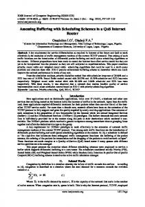
Design and Verification of VHDL Code for FPGA Based Slave VME Interface Logic It also has multiprocessing capability. The VME64x bus specification (ANSI/VITA 1.1-1997) is an extension of the VME64 standard ANSIVITA 1-1994. It defines a set of features that can be added to the VME and VME64 boards, backplanes and subracks. The structure of VME bus system is shown in Fig. 1. CONTROLLER Controls Access to the Bus Handles Interrupts
VME MASTER
SLAVE Allows Masters to Read/ Write Access
Bus Grant/Request R/W Interrupt Bus Data Bus Address Bus
Fig. 1: VME Bus System
III.
Typical Read/Write Cycle
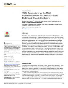
During a typical read/write cycle the master addresses a slave and then transfers Data through the data lines D00-D15 based on the control signals. For read and write operations, data strobes DS0* and DS1* must go low. For a read operation, master initiates the cycle by driving the address bus A01-A15/A01-A23, AM0-AM5, IACK* and LWORD*. These signals should be valid on the falling edge of AS*. WRITE* signal indicates the direction of data transfer. So the master negates WRITE* and asserts data strobes DS0* and DS1*. The slave decodes the address to check for a valid access and if so, the data is placed onto D00-D15 and then asserts data transfer acknowledge [DTACK*]. The master negates the data strobes after latching the data to inform slave the completion of transfer cycle. The slave then negates DTACK* and then the cycle is terminated. A write cycle is shown in the Fig. 2. In case of write cycle, master asserts the WRITE* signal and then places data onto the bus before either data strobe is asserted. Address
Valid
AM Code
Valid
AS* Valid
Data DS* DTACK*
Fig. 2: Write cycle timing diagram
IV.
Block Diagram of AOC
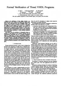
Fig. 3 indicates the top level block diagram of the AOC and it also shows the various interconnections between them. FPGA is chosen as the controller to interface the VME cycles and also to generate the required control signals for the DACs, Multiplexers and ADC.
www.iosrjournals.org
13 | Page
Design and Verification of VHDL Code for FPGA Based Slave VME Interface Logic
VME BUS
DACs Parallel DAC (0-2)
VME64x Interface & Control logic (FPGA)
Isolators Parallel/ Serial DAC (3)
(2nd level)
Output Connector
MUX
MUX ADC
V/I Convertor (0-3)
Amplifier
(1st level)
Isolators
Read Back Control Mechanism
Fig 3 Block Diagram of VME64x based Analog Output Card The specifications of the VME64x based analog output card are: 1. Number of channels :4 2. DAC resolution:14 bits 3. Accuracy:0.25% span 4. Type of output: Voltage/Current 5. Output range:0-10V/4-20 mA 6. Isolation (Channel-Channel):100Vrms (continuous) 7. Isolation (Input-Output) :100Vrms (continuous) 8. Load Resistance :2K Ω(min.) for Voltage output, 600 Ω(max.) for Current output 9. VME bus interface :A16/A24,D16 10. Read-back :Provided for each channel at DAC output Card output(isolated)
V.
Inputs-Outputs
The top level interface of the FPGA is as shown in Fig. 4. These signals are used to control data transfer through the VME interface. The VME side signals are vme_addr (address bus A01-A31), vme_as_n (address strobe AS*), vme_am (address modifier AM0-AM5), vme_ga_n (geographical address GA0*-GA4*), vme_lword_n (long word lword*), vme_iack_n (interrupt acknowledge IACK*), vme_iack_in and iack_out (interrupt acknowledge daisy chain (IACKIN*-IACKOUT*), vme_ds_1_n and vme_ds_0_n (data strobes DS0*-DS1*), vme_write_n (read/write signal WRITE*), irq7_1 (priority interrupt requests IRQ1*-IRQ7*), dtack_n (data transfer acknowledge DTACK*), bidir_data_bus (data bus D00-D31).
www.iosrjournals.org
14 | Page
Design and Verification of VHDL Code for FPGA Based Slave VME Interface Logic clk reset_n board_sel_sig_n
vme_addr
dtack_n
vme_as_n
iack_out
vme_am
irq7_1
vme_ga_n
DAC_wr_n
vme_lword_n
DAC_clr_n
vme_iack_n
DAC_data
vme_iack_in FPGA
vme_ds_1_n vme_ds_0_n vme_write_n ADC_busy ADC_data
DAC_addr SDAC_sync_n SDAC_sclk SDAC_sdin SDAC_clr_n SDAC_rstin_n ADC_rc_n bidir_data_bus mux_1_sel mux_2_sel
Fig. 4 Signal Interface of FPGA
VI.
Objectives of FPGA
The objectives of FPGA are as follows. 1. Interface with VMEbus. 2. Provide control signals to DAC for Writing/Reading back digital inputs, resetting outputs etc. 3. Provide control signals to MUX and ADC to implement analog to digital (A/D) conversion. 4. Provide diagnostic registers for testing bus interface.
VII.
FPGA Register Map
Table 1 shows the register map of the FPGA. Each register is 16-bit wide. Table 1: FPGA Register Map [A03-A01] Register name 000 DAC 0 001 DAC 1 010 DAC 2 011 DAC 3 100 Read back/ Convert Register 101 Diagnostic Register 1 110 Diagnostic Register 2 111 Status/ Reset Register
VIII.
Process in Detail
The VME bus Slave Core Component is a synthesizable VHDL core to incorporate the VMEbus slave function into an FPGA. The bus control functions are implemented inside the controller block. It monitors the Address and Data bus for the commands (Reads or Writes) sent to it. When the correctly decoded address is received, the Slave will either receive information from the data bus for a Write cycle or output information onto the Data bus in the case of a Read operation. The bus Master continues to control the Data bus during either interface. The DAC conversion starts by a VME write operation into the corresponding registers. By using the address bits vme_addr (3 down to 1), DACs are selected for updating or readback. For performing any operation on the DAC, FPGA must drive the data lines of the DAC and the address lines (dac_addr (1 down to 0)) that indicate which one of the 4 DACs has been selected. The write and clear signals are other DAC control lines driven by the FPGA. Analog to digital (A/D) conversion starts by VME write operation the vme_addr-100. The www.iosrjournals.org
15 | Page
Design and Verification of VHDL Code for FPGA Based Slave VME Interface Logic last three bits indicates the channel number of the analog output to be converted back. FPGA generates the select signals to the analog multiplexers (MUX) to select the corresponding channel based on these 3 bits of data. This AOC uses a two level multiplexer; 4:1 MUX select the field current analog values and 8:1 MUX selects the direct DAC outputs depending on the select lines. A delay is included to compensate the settling time of amplifiers. Then a Start of Conversion (SOC) command to ADC is given to start conversion. Once the ADC finishes conversion, End of conversion (EOC) signal is asserted. A Busy Bit (zeroth bit in status register) is used to indicate that the adc is functioning. Read-back/convert register stores the ADC output. If the CPU issues a conversion command when conversion is in progress, then the command will be ignored. The board can be reset through software by writing any word to the reset/status register. An interrupt interface is also included which can handle up to seven independent interrupts from the board.
Output signals
Internal Block Diagram of FPGA Latch and synchronization block
Input signals
Bidirectional tri state data buffer
IX.
Board select logic block
DTACK* signal generator
Tri state bus logic
Diagnostic register
Serial DAC control signal generator
Read back control logic block
Parallel DAC control signal generator
Fig. 5 Internal block diagram of the FPGA Fig. 5 shows the different modules used for interfacing the AOC to the VME64x bus. Latch and Synchronization block: It is used to latch the address and address modifier code and also to avoid the metastability condition [4] by synchronizing all the VME side signals. Board select Logic Circuit: To decide if an access is for the actual card or not, a decode logic has to be added externally. The signals vme_addr and vme_am allow a standard memory mapped address decoding scheme. The address modifiers may be used to differentiate between user/system access, io or memory etc. The vme_addr and vme_am signals are latched with the falling edge of as_n and are immediately valid. DTACK* signal generator: After the board select signal is asserted, based on the write* signal from the master, read or write cycle takes place. That means, the slave decodes the address and places the data onto the data bus for a read operation or receives the data in case of a write operation. Then it asserts the dtack* signal low to indicate that it has successfully received the data on a write cycle or to indicate that it has placed data on the data bus on a read cycle. DAC control signal generation: Five Digital to Analog Converters consisting of a Serial Input, 14Bit/16-Bit DAC and four 14-bit, parallel input Voltage output DAC are used in the Analog Output Card. The DAC control signal generator block generates the required control signals for the DAC present on the AOC. The PDAC accepts 14-bit parallel loaded data from the external bus into one of the input registers under the control of the WR and DAC channel address pins, A0–A2. The signals needed for the proper operation of the Parallel DAC are dac_wr_n, dac_data(14/16 bit), dac_addr(2 bit) and dac_clr_n. The signals needed for the proper operation of the Serial DAC are sdac_sync_n , sdac_sclk, sdac_sdin, , dac_clr_n, sdac_rstin_n, busy_bit. Read Back Control Block: The readback control circuit consists of a 2 level multiplexer circuit and an ADC. The output coming from the V/I converters are in the range of 4-20mA. An amplifier is also used to amplify output coming from the V/I converters before giving data to the second level MUX. The control signals needed for the proper working of readback control mechanism are mux_1_sel, mux_2_sel, adc_rc_n, data_out. Tri state Bus logic Circuit: Bi-directional bus means that devices connected to the bus can either take input from the bus, or put output on the bus. In order for this to happen without outputs colliding, tri-state buffers are used. When the buffer enable signal is low, the data is passed onto the data bus. Otherwise, a high impedance state is kept on the data bus. Diagnostic registers: They are used for checking the bus Interface lines. There are chances of faults like stuck at „1‟ or stuck at „0‟ faults occurring on the bus lines. Bit pattern “0101010101010101” are first written into the bus and read it through diagnostic registers. After that bit pattern “1010101010101010” is written and read back. So faults can be identified easily. www.iosrjournals.org
16 | Page
Design and Verification of VHDL Code for FPGA Based Slave VME Interface Logic X.
Design Structure and Test Approach
The designed FPGA is tested at module level and then tested on the whole at the top-level. That is, integrated FPGA is instantiated in the top-level Test Bench (TB) and all the interfaces of the FPGA are tested at the integrated top-level test bench. The RTL schematic for the Analog Output Card Controller is shown in Fig. 6.
Fig. 6 RTL Schematic
XI.
Conclusion
As part of this work, a major step towards designing the VMEbus controller (FPGA) using VHDL has been accomplished. The designed FPGA is a digital design, coded at Register Transfer Level (RTL) in VHDL, as per the requirements. A test bench was written to verify the functional and timing specifications of the FPGA.
References [1]. [2]. [3]. [4].
Field-programmable gate array - Wikipedia, the free encyclopedia. Douglas Perry, VHDL Programming (Tata McGraw Hill) An American National Standard, IEEE Standard for a Versatile Backplane Bus: VMEbus. Understanding metastability in FPGAs, ALTERA.
www.iosrjournals.org
17 | Page