Oct 27, 2014 - different ANSYS products and make design automation easier. 4 ... â¢Optimization outside ANSYS (Scripting: Python): ... using Test function).
Design Automation for ANSYS Workbench using VisualDOC Chen Liang (summer intern) Department of Civil and Environmental Engineering Vanderbilt University, Nashville, TN Oct. 27, 2014
VisualDOC Design Optimization for ANSYS Workbench
1
Chen Liang, Oct. 27, 2014
Overview
VisualDOC Optimization
Parametrization in ANSYS Workbench
Coupling method
Numerical Examples
User interface of VisualDOC
VisualDOC Design Optimization for ANSYS Workbench
2
Chen Liang, Oct. 27, 2014
VisualDOC Optimization • Integrated tool for design process integration, execution and automation • Single objective, multi-objective, DOE, Response surface, etc. • Visualized configuration and optimization flow
• Execution of external software to via batch mode
VisualDOC Design Optimization for ANSYS Workbench
3
Chen Liang, Oct. 27, 2014
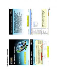
ANSYS Workbench
• Multidisciplinary engineering platform that integrates modeling, meshing, analysis and post-processing. • Change can be made to any part of the analysis, ANSYS Workbench will manage the execution of the required application to update the project automatically.
Parametric analysis facilitates management of parameters across different ANSYS products and make design automation easier VisualDOC Design Optimization for ANSYS Workbench
4
Chen Liang, Oct. 27, 2014
Coupling Tactic Two approaches for software coupling: Optimization outside ANSYS (Scripting: Python): Regard the ANSYS analysis as blackbox Specify the parameters within ANSYS Workbench
Call ANSYS from VisualDOC, extract variables from the parameter-set and classify the parameters into input and output files Run optimization, ANSYS Workbench will be executed in the batch mode
Optimizer as ANSYS plug-in (SDK: C#) Optimization within ANSYS (DesignXplorer) In progress VisualDOC Design Optimization for ANSYS Workbench
5
Chen Liang, Oct. 27, 2014
Flow Chart Problem Setup & Parametrization
Parameter classification
Solution Check
VisualDOC Design Optimization for ANSYS Workbench
Optimization
6
VisualDOC Setup
Chen Liang, Oct. 27, 2014
Numerical Examples Three examples are created to demonstrate VisualDOC design automation for ANSYS Workbench:
Single disciplinary single objective optimization for a heat transfer problem using Fluent
Multi-disciplinary multi-objective optimization for an aero-elastic wing analysis (FSI)
Response surface based multi-disciplinary optimization for an aero-elastic flapping problem (FSI transient)
VisualDOC Design Optimization for ANSYS Workbench
7
Chen Liang, Oct. 27, 2014
Heat transfer in a mixing elbow Mixed Flow
VisualDOC Design Optimization for ANSYS Workbench
8
Chen Liang, Oct. 27, 2014
Optimization Formulation Boundary conditions: Flows
Speed (m/s)
Temperature (K)
Cold inflow
0.2
293.15
Hot inflow
1.4
313.15
Mixed outflow
N\A
Output
Target:
Optimization setup:
Maximize the average outlet temperature: The Design variables include: • Inner radius of the torus: • Degree of the cylinder position angle: • Degree of the cylinder angle: VisualDOC Design Optimization for ANSYS Workbench
9
Chen Liang, Oct. 27, 2014
Software Coupling VisualDOC flow chart Extract defined parameter from ANSYS, and classify the input and output variables into two files (initially generated using Test function) Input file Execute ANSYS Workbench analysis Output file
VisualDOC Design Optimization for ANSYS Workbench
10
Chen Liang, Oct. 27, 2014
Define Parameters Synthetic variables:
All parameters in ANSYS Workbench
• The geometric parameters in ANSYS are the synthetic functions of the design variables. • Define synthetic variables in VisualDOC using the given equations. VisualDOC Design Optimization for ANSYS Workbench
11
Chen Liang, Oct. 27, 2014
Software Coupling Parameter Extraction
Run ANSYS
Script that extracts and classifies the variables
Script that executes ANSYS
Click Test to initialize input and output text files VisualDOC Design Optimization for ANSYS Workbench
12
Chen Liang, Oct. 27, 2014
Identify I/O Variable
Input file
Output file
Highlight and name the target string Highlight and name the corresponding values to write (read) VisualDOC identifies the values by relative positioning Note that the design variables are not necessarily the direct input to the model VisualDOC Design Optimization for ANSYS Workbench
13
Chen Liang, Oct. 27, 2014
Data Linker
No links since they are not direct inputs
VisualDOC Design Optimization for ANSYS Workbench
14
Chen Liang, Oct. 27, 2014
Results Best objective history
• Unconstraint optimizer: BFGS • 4 optimization iterations • 31 function evaluations
• 3,300 seconds on i-5 desktop • Temperature drop from initial 299.18 minimum 298.77
Initial
VisualDOC Design Optimization for ANSYS Workbench
Optimum
15
Chen Liang, Oct. 27, 2014
Multi-Objective Wing Design CFD
FEA Displacement
Pressure
Stress, deflection, etc.
Lift, drag, moment, etc
Targets: High lift-to-drag ratio Small wing deflection(stress) VisualDOC Design Optimization for ANSYS Workbench
16
Multi-objective optimization (Pareto Frontier) Chen Liang, Oct. 27, 2014
Optimization Formulation Model description: • NACA 0012 airfoil • Cantilevered wing • Turbulent model: • Inlet speed: 100m/s Optimization setup:
Design variables: • Backsweep angle (BSA) • Taper ratio (TR) • Root chord length (L) • Angle of attack (AoA) • Wing span (S)
Calculated in ANSYS or VisualDOC Optimizer: • Non-dominated sorting genetic algorithm – II (NSGA-II) multi-objective optimizer
• Population size: 20 (func eval / iter) • Maximum number of iteration: 20 VisualDOC Design Optimization for ANSYS Workbench
17
Chen Liang, Oct. 27, 2014
VisualDOC Setup
Design variable, but not direct input to the model
Synthetic functions VisualDOC Design Optimization for ANSYS Workbench
18
Chen Liang, Oct. 27, 2014
Result Pareto frontier: • Number of function evaluations: 400 • Total computing time: ~ 80 hours Optimal Pareto frontier
VisualDOC Design Optimization for ANSYS Workbench
• Grey points are Paretos from other iterations. • Best Pareto is given in blue dot One objective cannot be improved without worsening the other.
19
Chen Liang, Oct. 27, 2014
Response Surface Based Optimization
0.005 sec
Optimization Maximize the largest deformation Stress constraint
Design variables: plate height, thickness
VisualDOC Design Optimization for ANSYS Workbench
20
Chen Liang, Oct. 27, 2014
Design of Experiments Deform
Approach Optimal Latin Hypercube sampling Number of design points: 20
Total computational time: 168 min
Thickness
Height
Optimization using RSM Full-quadratic DOE model MMFD Optimizer: 7 iterations, 81 function evaluations Optimum: MaxDef = 7.61mm, 𝜎𝑣 = 60,300Pa
ANSYS Validation At the optimum: MaxDef = 5.13mm, 𝜎𝑣 = 93,261Pa VisualDOC Design Optimization for ANSYS Workbench
21
Chen Liang, Oct. 27, 2014
Large bias
Response Surface Approximated Optimization Approach Using the previous 20 design points Optimization validate result update RMS re-optimization 6 design points are added and the computational time is ~48 min
Deformation
Thickness
Height
Thickness
Height
Note that the response surfaces are built based on the weighted value of the points VisualDOC Design Optimization for ANSYS Workbench
22
Chen Liang, Oct. 27, 2014
Summary Coupled analysis for VisualDOC and ANSYS Workbench • Design automation using VisualDOC optimizers • Multi-disciplinary, multi-physics analysis and optimization based on ANSYS Workbench • Parameter management (ANSYS) and parameter identification (VisualDOC python) guarantee the non-intrusive analysis to preserve the integrity of ANSYS models
Features of methodology • Heat transfer in a mixing elbow • Multi-objective MDO for an aero-elastic wing • Pareto frontier • Design of experiments
• Response surface based optimization VisualDOC Design Optimization for ANSYS Workbench
23
Chen Liang, Oct. 27, 2014
Thank you !
VisualDOC Design Optimization for ANSYS Workbench
24
Chen Liang, Oct. 27, 2014