Nov 15, 2006 - the analysis of an MGDM point-to-point link, transparent to the transmission ..... “High capacity multi-service in-house networks using mode group ... [11] J. R. Barry, E. A. Lee, and D. G. Messerschmitt, Digital Communica- tions.
IEEE PHOTONICS TECHNOLOGY LETTERS, VOL. 18, NO. 22, NOVEMBER 15, 2006
2359
Design Considerations for a Transparent Mode Group Diversity Multiplexing Link C. P. Tsekrekos, Student Member, IEEE, A. Martinez, Member, IEEE, F. M. Huijskens, and A. M. J. Koonen, Senior Member, IEEE
Abstract—Mode group diversity multiplexing (MGDM) is an optical multiple-input–multiple-output technique that aims at creating independent communication channels over a multimode fiber, using subsets of propagating modes. This letter deals with the analysis of an MGDM point-to-point link, transparent to the transmission format. The geometry of a mode-group selective multi/demultiplexer is optimized in order to minimize the crosstalk among the channels. The power penalty is calculated when a zero-forcing algorithm is used to mitigate the crosstalk. Index Terms—Graded-index multimode fiber (GI-MMF), mode group diversity multiplexing (MGDM), optical multiple-input–multiple-output (MIMO), transparent optical link.
I. INTRODUCTION N SHORT-REACH optical networks, multimode fiber (MMF), primarily graded-index (GI) MMF, has been the medium of choice. Its large core diameter makes MMF splicing easier than that of single-mode fiber (SMF). On the other hand, the bandwidth of an MMF is significantly lower than that of an SMF in the classical intensity-modulation direct-detection approach. This is due to the differential mode delay (DMD) among the propagating modes. To enhance the performance of GI-MMF links, techniques such as selective mode launch [1] and spatially resolved equalization [2] can be applied. As a step further and aiming at the integration of several services—such as analog/digital TV, Internet traffic and voice—over a common optical infrastructure, different groups of modes can be excited and used as independent, parallel communication channels. This is the objective of the mode group diversity multiplexing (MGDM) technique [3]. MGDM is an optical multiple-input–multiple-output (MIMO) scheme that requires electronic processing of the received signals to mitigate the crosstalk among the channels. MIMO is a well-known principle in wireless communications to provide larger robustness and capacity. At the transmitter, sources, each exciting a different group of modes there are detectors selectively respond to a and at the receiving side different part of the near-field pattern (NFP) at the fiber output. . The more receiving antennas, the In MIMO systems larger the total received power. However, when the transmission medium is an MMF, the total received power remains constant
I
Manuscript received April 20, 2006; revised August 31, 2006. This work was supported in part by the Freeband Impulse Programme of the Ministry of Economic Affairs of the Netherlands. The authors are with the COBRA Research Institute, Eindhoven University of Technology, 5600 MB Eindhoven, The Netherlands (e-mail: c.tsekrekos@tue. nl). Color versions of Figs. 2 and 3 are available at http://ieeexplore.ieee.org. Digital Object Identifier 10.1109/LPT.2006.885282
and is simply split among the detectors. This is why preferably in the case of MGDM. In general, the relation between the received and the transmitted electrical signals is not simple. Propagation in the MMF introduces dispersion and mode mixing. However, in some cases this relation can take the form of a simple matrix [4]. In other is related to words, the received electrical signals vector via matrix , the transmitted electrical signals vector , where is a noise comi.e., ponent. If dispersion can be neglected, the transmission matrix are real-valued, expressing the proportion of the elements power transmitted by the th source and received by the th detransmitted tector. The signal processing unit recovers the is known. Electronic signals by matrix inversion, when processing and fiber dispersion bound the bandwidth of the link. can be arbitrary. In this sense, the However, the format of link is transparent. In this letter, a transparent MGDM point-to-point link is analyzed, yielding a scheme consistent with high coupling efficiency ( ) and simplicity. A significant part of the analysis is based on an experimental estimation of the optical crosstalk m silica GI-MMF, the among the channels, for a most commonly installed type of MMF. II. GEOMETRIC CONSIDERATIONS AND CROSSTALK ESTIMATION One way to selectively excite a GI-MMF is by launching a Gaussian beam at its front facet. Compared with other techniques, such as using a mask at the input of the GI-MMF [5] or side launch through a prism [6], excitation with a Gaussian beam is simple and provides high . The set of excited modes depends on the launch conditions, i.e., the beam waist radius, as well as the radial , angular , and axial offsets. These offsets refer to the radial and angular displacement of the beam with respect to the GI-MMF axis and the distance of the beam waist from the input facet of the GI-MMF. In order to obtain the narrowest possible mode spectrum, the beam waist should lie on the fiber facet (zero axial offset) with its radius varying according to the wavelength, the index profile, and the radial offset [7]. A good compromise is to use a standard (for a given wavelength) since this ensures SMF. The angular offset is chosen and, as it will be shown, yields a design inhigh for large dependent of the GI-MMF length. In the following, a 3 3 link will be discussed, serving as one. The multiplexer an example for the design of an consists of three radially offset beams. At the receiving side, a three-segment receiver geometry is proposed. The segment areas are chosen so as to minimize the crosstalk among the channels.
1041-1135/$20.00 © 2006 IEEE
2360
IEEE PHOTONICS TECHNOLOGY LETTERS, VOL. 18, NO. 22, NOVEMBER 15, 2006
value of . Assuming linear superposition of the three power coefficients can be distributions at the GI-MMF output, the estimated by
where
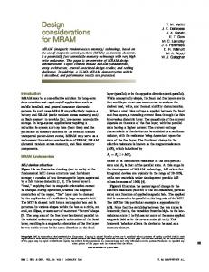
is the intensity distribution of the NFP caused by the polar coordinates on the fiber facet with on is the area of the th receiver segment, and the fiber axis, the core radius of the GI-MMF. The resulting matrix is Fig. 1. NFP at the output of a 62:5=125 �m silica GI-MMF under selective excitation with a radially offset beam.
Fig. 2. (a) Normalized annular flux of the NFP at the output of a 75-m 62:5=125 �m silica GI-MMF, when the latter is excited by a radially offset beam. (b) Three-segment MGDM receiver geometry based on (a).
A 660-nm Fabry–Perot laser diode pigtailed to a 1 m SMF with mode field diameter 4.2 m and numerical aperture (NA) 0.12 was used to selectively excite three samples of m silica GI-MMF, with central NA 0.275, of lengths 1 m, 75 m, and 1 km. The SMF output was launched on the input facet of the GI-MMF with radial offsets of 0, 13, and 26 m, , and of the investigated corresponding to beams multiplexer scheme. The position of the SMF was controlled by computer-driven translational stages. The NFP at the GI-MMF , NA 0.75) output was observed through a microscope ( with a charged-coupled device (CCD) camera. The laser was operating above threshold and the 75-m and 1-km fibers were placed around a 15-cm diameter drum. In a real MGDM link, the three beams should be launched simultaneously. This can be achieved by means of a laser array or a planar waveguide [8]. The NFP has a disk shape whose radius length is similar to the radial offset of the launched beam (Fig. 1). It is evident that the disk radius is practically independent of the GI-MMF length, indicating that mode mixing is limited. Similar NFPs have been observed at 1300-nm wavelength [8]. Fig. 2(a) depicts the spatial overlap among the normalized annular flux of the three MGDM channels for the 75-m fiber. The result is similar for the other two fibers. The annular flux is the integrated over the fiber facet [9]. Due intensity between radii and to the circular symmetry of the GI-MMF, a circular three-segment receiver geometry is proposed, consisting of three annular segments [Fig. 2(b)]. The three radii that define the receiver seg, , and m. In legacy ments are GI-MMF, defects may occur in the refractive index profile, primarily close to the GI-MMF axis. This may mainly affect the
presented in the form . The matrix was similar for laser operation below threshold. The total optical crosstalk at is (dB). The receiver radii of the investigated 3 3 link minimize the crosstalk, given the input beams. For the 75-m fiber, , , and dB, crosstalk at channel 1, 2, and 3 is coefficients vary very moderately with respectively. The the GI-MMF length. Therefore, the dependence of the power budget of the proposed MGDM link on the fiber length will be mainly due to the fiber loss. Crosstalk could be reduced by bounding the propagating and . Annular NFPs power in the th channel between to the can be observed by introducing an angular offset input beams, in accordance with the launch of helical rays [10]. However, the thickness of such patterns varies with the fiber length. In addition, clear annular patterns appear when the coherence time of the source is very small, as in LEDs. Furthermore, in the case of the investigated 3 3 system, would result in very low introducing an angular offset to due to the small local NA. III. POWER PENALTY ANALYSIS A mode-group selective multi/demultiplexer has been hitherto proposed and the optical crosstalk among the channels has been estimated. To recover the input signals, electrical processing is required. For MGDM, the simplest receiver architecture is matrix inversion, a zero-forcing method in line with the requirement of service transparency [11]. In this section, we calculate the power penalty as a result of matrix inversion, and we examine its sensitivity to misalignments. After matrix inversion, the estimated transmitted signals are , where represents the noise from the demultiplexing unit and is an estimate of the inverted matrix . Assuming ideal channel estimation, i.e., . It is clear that, although matrix inversion recovers the transmitted and designals, noise increases. The two noise terms pend on the specific implementation of the receiver. To calcu, since late the power penalty, we focus on the term this term expresses the noise enhancement due to the demultiplexing algorithm. The variance of the noise at the th channel , where are the statistically inis dependent elements of the noise vector .
TSEKREKOS et al.: DESIGN CONSIDERATIONS FOR A TRANSPARENT MODE GROUP DIVERSITY
2361
TABLE I AVERAGE (MAXIMUM) POWER PENALTY, OPTICAL CROSSTALK, AND GEOMETRIC DESIGN PARAMETERS FOR AN N N MGDM SYSTEM
2
Fig. 3. Influence of misalignments on the power penalty of the mostly affected channel of (a) a 3 3 and (b) a 4 4 MGDM link. A1 corresponds to no mis�m and �m misalignment alignment (Table I). B1 and C1 correspond to at the transmitting side. A2, B2, and C2 correspond to A1, B1, and C1 with 2 �m misalignment at the receiving side.
2
2
+2
02
IV. CONCLUSION We distinguish the two cases where either shot or thermal noise is the prevalent noise source. The first one gives a fundamental limit of the system performance, while the second one is practically always present. Other sources of noise, such as modal noise, do not have a fundamental limit and are more related to the temporal behavior of the system. The signal-to-noise , where ratio (SNR) at the th channel is is the average power defined by the bias of the lasers. In the . The noise variance following, we assume that at the shot noise limit is and at . The power the thermal noise limit penalty at the th channel of an MGDM link is
In this letter, we have provided geometric considerations for an MGDM multi/demultiplexer, in the context of a simple transparent link. We have shown the tradeoff between the number of channels and the power penalty when a zero-forcing algorithm is used to demultiplex the received electrical signals. For the case m silica GI-MMF, to maintain robustness against of m), the number of channels should small misalignments ( not exceed three. The same approach can be applied to other types of GI-MMF, e.g., polymer optical fibers, viewed as suitable candidates for in-house networks [3]. ACKNOWLEDGMENT The authors would like to thank Dr. P. Matthijsse (Draka Comteq) for useful discussions and for providing the silica GI-MMF samples. REFERENCES
where is the average power required to maintain the SNR of the single-channel case. Table I shows the average and maxsystem imum power penalty and optical crosstalk for an with . It also gives the corresponding geometric parameters for the design of the multi/demultiplexer. Apart from optimizing the receiver radii, optimal offsets of the input beams have have been approximated as well. The matrix elements been measured using the 75-m fiber. A feature of MMF links is tolerance in alignment. In order to maintain this feature, the radially offset-most beam should lie , where is the maximum radial offset at the required tolerance in alignensuring a desired and ment. However, misalignments will change the spectrum of excited modes, and consequently the NFP. This will affect the crosstalk and therefore the power budget. Fig. 3 shows the influence of misalignments on the power penalty of channel 1, which is the mostly affected channel of the proposed MGDM link with and . The same tolerance m has been used at the transmitting and the receiving side. The 3 3 link is much more robust than the 4 4 one. The latter is primarily affected by the 2- m misalignment at the transmitting end, since a smaller part of the fiber core is used to propagate the optical signals.
[1] L. Raddatz, I. H. White, D. G. Cunningham, and M. C. Nowell, “An experimental and theoretical study of the offset launch technique for the enhancement of the bandwidth of multimode fiber links,” J. Lightw. Technol., vol. 16, no. 3, pp. 324–331, Mar. 1998. [2] K. M. Patel and S. E. Ralph, “Enhanced multimode fiber link performance using a spatially resolved receiver,” IEEE Photon. Technol. Lett., vol. 14, no. 3, pp. 393–395, Mar. 2002. [3] T. Koonen, H. P. A. van den Boom, I. T. Monroy, and G. D. Khoe, “High capacity multi-service in-house networks using mode group diversity multiplexing,” in Proc. OFC 2004, Los Angeles, CA, Feb. 22–27, 2004, Paper FG4. [4] H. R. Stuart, “Dispersive multiplexing in multimode optical fiber,” Science, vol. 289, pp. 281–283, July 14, 2000. [5] S. Berdagué and P. Facq, “Mode division multiplexing in optical fibers,” Appl. Opt., vol. 21, no. 11, pp. 1950–1955, Jun. 1, 1982. [6] P. S. Szczepanek and J. W. Berthold III, “Side launch excitation of selected modes in graded-index optical fibers,” Appl. Opt., vol. 17, no. 20, pp. 3245–3247, Oct. 15, 1978. [7] J. Saijonmaa, A. B. Sharma, and S. J. Halme, “Selective excitation of parabolic-index optical fibers by Gaussian beams,” Appl. Opt., vol. 19, no. 14, pp. 2442–2452, Jul. 15, 1980. [8] C. K. Asawa, “Intrusion-alarmed fiber optic communication link using a planar waveguide bimodal launcher,” J. Lightw. Technol., vol. 20, no. 1, pp. 10–18, Jan. 2002. [9] J. B. Schlager, M. J. Hackert, P. Pepeljugoski, and J. Gwinn, “Measurements for enhanced bandwidth performance over 62.5 �m multimode fiber in short wavelength local area networks,” J. Lightw. Technol., vol. 21, no. 5, pp. 1276–1285, May 2003. [10] M. Calzavara, R. Caponi, and F. Cisternino, “Selective excitation of annular zones in graded index multimode fiber,” J. Opt. Commun., vol. 5, no. 3, pp. 82–86, Jul. 15, 1984. [11] J. R. Barry, E. A. Lee, and D. G. Messerschmitt, Digital Communications. Norwell, MA: Kluwer, 2004.