1
Design Considerations for Deploying Underwater Sensor Networks Raja Jurdak∗ , Antonio G. Ruzzelli∗ , Gregory M.P. O’Hare∗ , and Cristina Videira Lopes† ∗ University College Dublin Belfield D4 Ireland {raja.jurdak, ruzzelli, gregory.ohare} @ucd.ie † University of California, Irvine CA 92697 U.S.A
[email protected]
Abstract— The reliance of underwater network deployments on specialized hardware for acoustic communication and modulation has impeded wide scale deployments of underwater sensor networks. This paper examines a system that integrates software modems with generic speakers and microphones that are builtin to sensor modules for establishing underwater acoustic links. The system enables cheap and easily deployable underwater sensor networks. Building on our recent field experiment in a river, canal, pond, and swimming pool, this paper outlines the technical and logistical challenges for deploying software-driven underwater sensor network. The software modem design choices include methods for signal modulation at the sender, and symbol synchronization, signal filtering, and signal demodulation at the receiver. Higher layer communication protocol issues for MAC and routing are also discussed, with a focus on cross-layer design to optimize the usage of scarce bandwidth and energy resources in the system. Practical solutions to logistical deployment challenges, such as waterproofing and casing, calibration, and fouling are proposed. The design guidelines in this paper lay the groundwork for further development of software-driven of underwater sensor networks.1
I. I NTRODUCTION The design of underwater communication systems has so far relied on expensive specialized hardware for acoustic communication and modulation. The conventional reliance on hardware acoustic modulation has stemmed from low processing speeds that did not allow the modulation of acoustic signals in software. Software modulation and demodulation [3, 4] is a recent alternative approach which overcomes most of the drawbacks of hardware modems. Recent advances in miniaturization and circuit integration have yielded smaller and more powerful processors that are capable of efficiently running acoustic modulation and demodulation software. Software modulation also provides a higher level of flexibility for on-the-fly tuning of modulation parameters, such as the data transfer rate and 1 This material is presented to ensure timely dissemination of scholarly and technical work. Copyright and all rights therein are retained by authors or by other copyright holders. All persons copying this information are expected to adhere to the terms and constraints invoked by each authors copyright. In most cases, these works may not be reposted without the c explicit permission of the copyright holder. °2007 IEEE. Personal use of this material is permitted. However, permission to reprint/republish this material for advertising or promotional purposes or for creating new collective works for resale or redistribution to servers or lists, or to reuse any copyrighted component of this work in other works must be obtained from the IEEE.
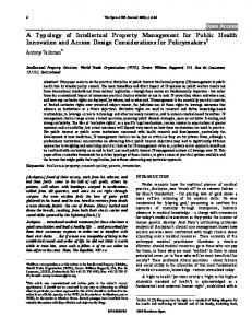
symbol duration, to suit the variable conditions of a particular deployment environment. Coupling software modems with generic microphones and speakers that are built-in to off-the-shelf sensor modules eliminates the need for specialized communication hardware and reduces system cost, facilitating the dense deployment of motes to form underwater acoustic sensor networks. The use of low power generic acoustic hardware and software modems for underwater communication yields a low bit rate in the order of tens of bits per second. The achievable bit rate of the proposed system is sufficient for monitoring sensor networks, such as for environmental or habitat monitoring. In monitoring networks, the nodes sample their sensors and send the data once during each update period, typically in the order of minutes. Since each node must send only a handful of sensor values during each update period, a data transfer rate in the order of tens of bits per second provides more than enough throughput to communicate all the sensor values during an update period. The target network application is expected to consist of general purpose sensor modules that use software modems and generic hardware to communicate acoustically in shallow water and send the data to the base station. Figure 1 sheds more light on the target network application. We expect to deploy a network consisting of tens to hundreds of sensor modules in a shallow water environment. The sensor modules can communicate acoustically through wireless multihop links. The modules periodically sample their sensors, collecting physical indicator data such as temperature and salinity, which influence pollution levels in the water. After sampling their sensors, the nodes report their data to a surface node nearby. The surface node, known as the base station, consists of a portable computer or PDA with a water-immersed acoustic transceiver that communicates with the underwater nodes. The computer is also equipped with a long range wireless broadband communication card that uses a cellular or satellite connection. The computer streams the network data towards a central database that acts as the main data repository. The collected data will feed into a data repository that archives historical data from the monitored area. The proposed network deployment will stream near-real time data from the aquatic environment into the data repository, providing professionals in the water management and research communities with access to sizeable and timely data from the water. The application will also leverage existing environmental information
2
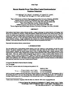
management platforms [5] for providing the tools necessary for analyzing, displaying, and sharing the collected data. The work described in this paper outlines the design considerations for the development of software-driven underwater sensor networks for monitoring pollution indicators in rivers, lakes, estuaries, and coastal areas and subsequently providing the data to environmental engineers in near realtime. While recent surveys cover underwater acoustic networks [1] and practical issues in these networks [2], the focus here is on software-driven underwater sensor networks in shallow water. In particular, this paper leverages our recent field experiments to identify suitable design choices for the acoustic communication link including signal modulation, symbol synchronization, filtering, and demodulation. The paper also visits MAC and routing layer issues and proposes minimalist cross-layer design to cope with limited bandwidth and energy resources of underwater sensor networks. Our field experiments have also revealed several logistical issues for underwater sensor network deployments, including waterproofing, casing, calibration, and fouling. Concrete solutions to these logistical issues are addressed. The rest of the paper is structured as follows. Section II discusses the technical design considerations of the software modems in detail. It also touches on the higher layer communication protocol design, including cross-layer optimizations for minimizing overhead. Section III presents the logistical challenges faced during our field experiments and proposes solutions for overcoming these challenges. Section IV concludes the paper. II. T ECHNICAL C ONSIDERATIONS This section examines technical considerations for the establishment of wireless underwater acoustic communication links through software, with a focus on the physical layer issues. The latter part of the section briefly discusses higher layer considerations. A. Physical Layer The physical layer design for our system involves both communication and modulation. The communication hardware is simply the microphone and speaker built-in to sensor nodes, serving as receiver and transmitter respectively. The focus then, is on signal modulation, which takes place through software resident on the motes. Figure 2 shows the block diagram for the communication system. The following discussion explores the main components of Figure 2 separately. 1) Modulation: The first component of the acoustic communication system is software modulation, that takes digital data as input and modulates an acoustic signal with the data. The potential choices of modulation schemes for software modems include amplitude shift keying (ASK), phase shift keying (PSK), and frequency shift keying (FSK). ASK varies the signal amplitude to encode digital data into the signal. Propagation effects, interference, and frequency selective fading in different underwater scenarios are variable and unpredictable, which renders the use of ASK in low-power underwater networks impractical. PSK encodes digital data by
changing the signal phase. A key challenge for using PSK with off-the-shelf sensor modules is that typical PSK receivers incorporate an array of receivers [2], an option that is not available in off-the-shelf modules. Augmenting the sensors with receiver arrays is not an option either, as it increases system cost and violates the off-the-shelf design strategy. In general, FSK uses 2N frequencies to encode N bits per frequency. The signal demodulation at the receiver can use low complexity techniques, such as the Fast Fourier Transform (FFT), to determine the frequency content of the signal. By choosing a number of frequencies that have high signal-tonoise ratio (SNR) for the channel and by ensuring sufficient spectral separation between the frequencies, FSK can provide robust underwater communication for low power transmissions with minimal processing complexity at the receiver. We recently performed an empirical study to investigate the spectral properties of the underwater channel in a controlled water environment [6]. The study used the Tmote Invent from Moteiv [9] module speaker as the transmitter of acoustic signals and a generic PC microphone as the receiver. The components were waterproofed using off-the-shelf elastic latex membranes that vibrate sufficiently to preserve most the acoustic properties of the speaker and microphone. The study evaluated the SNR of frequency tones between 400 and 6700 Hz at 100 Hz increments. The selection of the 100 Hz band separation between frequencies provides for low complexity frequency detection at the receiver. Note that narrower separation bands enable the use of more frequencies within the same available bandwidth, which increases bit rates but also reduces signal quality at the receiver. In general, there is a tradeoff in digital modulation techniques between the number of signal levels (in phase, amplitude, or frequency) and the quality of the signal. In our case, increasing the number of frequencies by using narrower frequency bands requires the use of higher order filters or FFT transforms at the mote to decode the signal. This is not feasible with the limited processing power of the motes. The study revealed that the channel, which includes the speaker, latex membranes, the water, and the microphone, exhibits the highest SNR at frequencies in the range of the 1000 Hz to 2500 Hz. The SNR drops steadily at frequencies above 3 Khz. Building on these results, we designed a software FSK modem that uses 8 frequencies in the 1-2.5 Khz range to represent 8 symbols of 3 bits each. The testing of the modem investigated 4 different bit rates from 6 bps to 48 bps, by varying the symbol duration from 500 ms to 62.5 ms. The experiment results revealed a low bit error rate for all data transfer rates within a transmission distance of 17 m, which was the size of the testing area. The output of the modulator block is a modulated acoustic signal that is then transmitted over the wireless medium through the built-in speaker. 2) Symbol Synchronization: The transmitted signal is received by the microphone at another node, on which the software then proceeds in the decoding process. Essential to acoustic communication with software modems is the ability of the receiver to synchronize to the first symbol of an incoming data stream. Traditional symbol synchronization approaches rely on
3
Interactive Maps
Base station Broadband Radio Connection To Internet
laptop
Simulation and Analysis tools data repository
Surface buoy
Acoustic links
Underwater sensor nodes Query and Download tools
Fig. 1.
Target network application
Digital data
Modulator
Modulated acoustic signal
Speaker
Transmitted mechanism [11], that uses Short Signature Synchronization acoustic signal Symbols (S 4 ) to align symbol boundaries at the receiver. The
(a) Received signal at microphone
Microphone
S4
Filter (Bandpass or FFT)
Synch
Demdoulator
(b) Fig. 2. Block diagram for software modem (a) Modulator/Transmitter (b) Demodulator/Receiver
the transmission of a predefined sequence of symbols, often referred to as a training sequence. The conventional approach makes two assumptions about the communication channel that do not hold for software-driven acoustic communications, namely: (1) a bit rate at least in the order of tens of kilobits per second; (2) a bit error rate (BER) in the order of 10−6 or lower. Software-driven acoustic communication, both aerial and underwater, supports lower bit rates that range between tens to hundreds of bits per second [4, 6–8]. In addition, the bit error rate of software-driven acoustic communication is several orders of magnitude higher than the radio frequency bit error rate. The higher bit error rate in acoustic communications tends to cause loss of training sequence symbols, preventing proper symbol synchronization. Furthermore, providing high redundancy in the training sequence to mitigate training symbol losses is not an option for the narrow usable bandwidth of software-driven acoustic communications. We recently proposed and tested the S 4 synchronization
design of the signature symbol aims at a high probability of correlation at the receiver even in cases of partial loss of the symbol and at low probability of false synchronization with ambient noise or data symbols. To this end, the symbol features include two square waves, with each square wave transmitted at a predefined frequency, separated by a predetermined guard time. The use of two frequencies for the signature symbol mitigates the effects of frequency selective fading or interference. The signature symbol guard time duration is chosen so that it is not equal to, and not a constant multiple of, the inter-symbol guard times to avoid high correlation with data symbols. In sum, the signature symbol features that promote high correlation at the receiver despite potential signal losses are the two frequencies, the duration of the square wave signals, and the guard time. The output of the S 4 provides the index of the first data sample in the received signal. 3) Filtering: The receiver then proceeds to filter the received signal. Filtering the acoustic signal at the receiver minimizes the effect of out-of-band noise on the decoding process. A suitable choice of filtering method depends highly on the processing capability of at the receiver. Our system currently provides two filtering methods, with the first method employing narrow bandpass filters at the relevant frequencies. The second filtering method applies a Fast Fourier Transform (FFT) to the received signal and examines the signal amplitude at the FFT samples corresponding to the relevant frequencies. The narrowband filtering method provides a finer signal quality as it only focuses on the frequencies of interest and excludes all interference outside this spectrum. The superior performance of the narrowband filtering method comes at the cost of higher processing activity at the receiver. In fact, the narrowband filtering method is suitable for running on a PC or
4
a PDA that acts as a base station for the underwater network, as in Figure 1. The FFT method can run on the motes themselves as it lower processing complexity. Running the FFT method on motes enables the deployment of a multi-hop network where nodes can autonomously decode, process, and relay received signals. The FFT method provides a coarser signal quality than filtering since it does not exclude interference from outside the frequency spectrum of interest. 4) Demodulation: The filtered signal then proceeds to the demodulator component. The demodulator begins examining the signal at the first data sample, which has been determined by the S 4 block. Starting at the first data sample and taking the number of samples that corresponds to one symbol, the demodulator determines the frequency component with the highest amplitude within this window, and outputs the data symbol corresponding to the highest frequency. For subsequent bits, the demodulator shifts the start sample of the previous symbol by the symbol length, and repeats the process of determining the strongest frequency component. B. Communication Protocols The design of the higher layer communication protocols for this system should adopt a minimalist approach to avoid creating high overhead in this bandwidth and energy limited system. The MAC protocol design for underwater sensor networks cannot exploit traditional low duty cycle protocols for terrestrial sensor networks. The reason is that the energy cost of transmission is generally much higher than the cost of signal reception in underwater networks, whereas the cost of transmission and reception is almost the same in terrestrial sensor networks [13]. Thus, signal transmissions dominate the energy consumption profile of underwater nodes. As such, the MAC protocol design should minimize control overhead messages, such as RTS and CTS, rather than implementing sleep policies. One possibility for our system is to use burst tones at the beginning of transmission to reserve the channel. In particular, the S 4 preamble can serve as a burst tone for reserving the channel at the MAC layer. For routing data towards the surface node, our communication system advocates the use of short multi-hop links for deploying dense underwater sensor networks. Keeping in line with the system’s minimalist approach, the network should make use of simple multi-hop routing techniques, such as the directed broadcast with overhearing method of MERLIN [14]. The relatively low cost of receiving signals actually favors the use of overhearing. Our recent study on the upper bounds for transmissions in directed broadcast networks with overhearing has shown that this method has only few redundant packet, resulting in low overhead for large networks. The proposed communication protocol design concepts exploit cross-layer interactions [15] to optimize the use of bandwidth and energy resources for this system. The use of the S 4 preamble from the physical layer to reserve the MAC channel exemplifies one cross-layer design coupling mechanism to limit overhead. Another example is overhearing packet at the MAC layer to suppress the transmission of duplicate packets.
We expect that further cross-layer optimization opportunities will arise as the project advances. The multi-hop topology of our network aims at limiting disruption to marine wildlife. Sending high power sound waves underwater has implications for marine wildlife, such as whales and dolphins. Recently, there have been several incidents in which whales or dolphins were disoriented and stranded because of human noise pollution resulting from sonar, oil exploration, and shipping [10]. Avoiding adverse effects on marine biology is a major consideration for environmental preservation. Because our network relies on multihop short range low power links between sensor nodes, it minimizes sound interference with the marine wildlife. III. L OGISTICAL C ONSIDERATIONS Underwater sensor network deployments involve a plethora of logistical challenges, which include waterproofing and casing, calibration, and fouling. The following discussion visits each logistical challenge separately. A. Waterproofing and Casing The most common waterproofing method for underwater communications hardware is to place the hardware in a custom-designed waterproof case with a special air-locked hole for the hydrophone and transducer that are in contact with the water. The cost associated with the material and design of the custom-designed casing strategies significantly increases system cost and discourages large scale deployments of underwater sensor networks. Our project’s design strategy advocates the use off-theshelf components not just for communication and sensing, but also for the protection and waterproofing of the components. As such, our design places the sensor nodes in elastic latex membranes that are cheap and readily available on the market. The latex membranes take the form of a balloon that is sealed to waterproof the sensor nodes. Since the sensor module includes the speaker and microphone, these acoustic communications components are also fully enclosed within the latex membranes. The elasticity of the membranes ensures that the acoustic waves transmitted by the speaker are transferred to the water through the elastic membrane. At the receiver side, the membranes vibrate upon the reception of an acoustic signal, transferring the signal to the interior of the membrane where the microphone can detect it. The use of the latex membranes causes relatively small reductions in signal amplitude. Our recent study [12] compared the suitability of two membranes for waterproofing the sensor nodes: (1) a vinyl membrane; and (2) a latex membrane. Table I illustrates the percentage of correctly received symbols for bit rates ranging between 6 bps and 96 bps for both membranes. The vinyl membrane experiments were conducted with a generic PC speaker as a transmitter, while the latex membrane experiments were conducted with Tmote Invent speakers of comparable power rating. The results in Table I show that the latex membrane has a better coupling with the water, yielding a notably lower bit error rate at the higher transmission rate of 48 bps.
5
Air
River Dodder
(a)
(b)
Grand Canal
Ranelagh Ponds
(d)
(c)
Fig. 3. Shape of S 4 symbol as received at the Tmote Invent speaker in (a) Indoor aerial channel (b) River Dodder (c) Grand Canal in Dublin and (d) Ranelagh Gardens pond.
Transfer rate (bps) Latex mem. Up to 17m Vinyl mem. Up to 10m
6
12
24
48
96
≥95%
≥90%
≥81%
≥79%
N/A
N/A
≥90%
≥78%
≥35%
≥10%
TABLE I C OMPARISON OF THE PERCENTAGE OF SYMBOLS CORRECTLY RECEIVED FOR THE PC SPEAKERS AND T MOTE I NVENT EXPERIMENTS
B. Calibration Our field tests in different bodies of water, including swimming pools, ponds, rivers, and canals, have revealed a distinct background noise and interference pattern in each case. For instance, the primary noise source in swimming pools is water pumps, whereas the noise sources in a river include currents and wildlife activity. The dependance of the noise profile on the deployment environment requires calibration steps, which could be manual or automatic, prior to placing the sensors in the water. Fortunately, the implementation of modulation and communication in software provides maximum flexibility for performing on-the-fly calibration. A central issue for calibration is the frequency-selective noise in the deployment environment. The choice of frequencies for the S 4 synchronization symbol must avoid frequencies with high noise in a particular deployment environment. The selection of the S 4 frequencies is critical for proper system operation, as choosing unsuitable frequencies causes large synchronization errors, resulting in many bit misalignments. Similarly, it is also important to to choose data symbol frequencies that avoid the high noise frequencies. The selection of the suitable frequencies for S 4 synchronization and the data symbols can be done automatically. During
an initial setup phase, one node, typically the base station, can be designated as a calibration receiver, and another as a calibration transmitter. Upon deployment, the designated transmitter sends an apriori known calibration signal that includes a diverse set of S 4 symbols with different frequency combinations, followed by a sequence of frequency tones that covers all the possible symbol frequency tones. Another set of S 4 symbols serves as a post-amble to conclude the reference signal. The designated receiver processes the calibration signal by comparing the processed signal against a locally stored version of the reference signal. The receiver then selects the frequencies that have been received with the highest SNR, and transmits a short broadcast message indicating these frequencies to the other nodes.
Another calibration issue is ensuring that the stored S 4 symbol at each node is representative of the symbol as it is received in the current deployment environment. Our field experiments have shown that the structure of a received S 4 symbol with the Tmote Invent microphone in air is different than the structure in water. As Figure 3 shows, the structure even varies across different water media, depending on the current, depth, and suspended solids in the water. For instance, the envelope of the S 4 symbol differs significantly when the signal is received in the river (Figure 3(b)) and in the pond (Figure 3(d)). The plots in Figure 3 illustrate that the relative amplitude of each of the square signals changes depending on the medium. Other signal artifacts, such as impulses at the beginning or end of the signal, are also dependent on the deployment environment. As such, each node should store at least one instance of the S 4 symbol as it is received in the current deployment environment. This maximizes the probability of successful correlation and synchronization through the S 4 mechanism.
6
C. Fouling Fouling is a process by which marine wildlife, such as barnacles, zebra mussels, weeds, and algae attach themselves to still object in the water. Fouling is an important consideration for the deployment of underwater sensors that remain stationary in the water for prolonged periods. For this project, avoiding fouling effects is especially important since the attachment of organisms to the membrane could limit or change the membrane’s vibration characteristics. Traditional anti-fouling approaches include the use of special copperbased paints to prevent the attachment of organisms to boat bottoms. Current research focuses on developing alternatives to paint-based solutions, which are harmful to the ambient environment. For example, Port Zlande in New Zealand is developing a way to strip layers of dirt from boat hulls which is absolutely safe for the environment [16]. Our project aims at protecting the environment, and not damaging it in the process, so we intend to adopt one of the emerging anti-fouling techniques. One interim solution under consideration is to place the nodes in the latex membranes and then to fix the membranes inside a resilient cubic plastic box whose purpose is to shield the nodes from fouling and other hazards in harsh underwater environments. The surfaces of the plastic box would be perforated to maintain acoustic coupling between the box contents and the outside medium. IV. C ONCLUSION This paper has presented the lessons learned so far from our field experiments with software-driven underwater sensor networks. The main technical challenges include the design and integration of the modulation, synchronization, filtering, and demodulation techniques for the software modems. The design of higher layer communication protocols for this system should also adopt a minimalist approach to minimize control overhead. This requirement will likely benefit from crosslayer design to enable various layers to better coordinate their functions. Logistical considerations for underwater networks depend on the deployment environment. We have identified common logistical considerations low-power underwater networks, which include the need for resilient waterproofing and casing, calibration, and anti-fouling measures. Our initial experiments in various bodies of water have exposed the benefits of using software modems for underwater communications capable of functioning on off-the-shelf multi-purpose sensors. The design guidelines in this paper lay the groundwork for further development of software-driven of underwater sensor networks. R EFERENCES [1] I.F. Alkyildiz, D. Pompili, and T. Melodia. “Underwater Acoustic Sensor Networks: Research Challenges,” ’newblock Elsevier Ad Hoc Networks, 3(3):257-279, May 2005. [2] J. Partan, J. Kurose, and B. N. Levine. “A Survey of Practical Issues in Underwater Networks,” In Proc. The First ACM International Workshop on UnderWater Networks (WUWNet), 2006. [3] C. V. Lopes and P. Aguiar. “Acoustic Modems for Ubiquitous Computing,” IEEE Pervasive Computing, Mobile and Ubiquitous Systems, Summer 2003.
[4] R. Jurdak, C.V. Lopes, and P. Baldi. “Software Acoustic Modems for Short Range Mote-based Underwater Sensor Networks,” In Proc. of IEEE Oceans Asia Pacific. Singapore. May, 2006. [5] California Sustainable Wetland/Watershed Information Manager. available at: www.calswim.org. [6] R. Jurdak, P.M.Q. Aguiar, P. Baldi, and C.V. Lopes. “Software Modems for Underwater Sensor Networks,” To appear in proc. of IEEE/OES Oceans - Europe ’07, Aberdeen, Scotland. June, 2007. [7] R. A. Iltis, H. Lee, R. Kastner, D. Doonan, T. Fu, R. Moore and M. Chin. “An Underwater Acoustic Telemetry Modem for Eco-Sensing,” In proc. MTS/IEEE Oceans’05, September 2005. [8] T. Fu et al. “Design and Development of a Software-Defined Underwater Acoustic Modem for Sensor Networks for Environmental and Ecological Research,” In proc. MTS/IEEE Oceans, September, 2006. [9] MoteIV Corporation available at: www.moteiv.com [10] R. Black. “Research Needed on Marine Sound,” BBC News article, available: news.bbc.co.uk/2/hi/science/nature/4706670.stm [11] R. Jurdak, A. G. Ruzzelli, G.P.M. OHare, and C. V. Lopes. “Reliable Symbol Synchronization in Acoustic Sensor Networks,” Submitted to IEEE GlobeCom, 2007. [12] R. Jurdak, P. M.Q. Aguiar, P. Baldi, and C.V. Lopes. “Software Acoustic Modems for Underwater Sensor Networks,” Submitted to IEEE Journal on Oceanic Engineering, November, 2006. [13] P. Harris, M. Stojanovic, and M. Zorzi. “When Underwater Acoustic Nodes Should Sleep With One Eye Open: Idle-time Power Management In Underwater Sensor Networks,” In Proc. The First ACM International Workshop on UnderWater Networks (WUWNet), 2006. [14] A. G. Ruzzelli, G.M.P O’Hare, M.J. O’Grady, and R. Jurdak. “MERLIN: Cross-layer Integration of MAC and Routing for Low Duty-Cycle Sensor Networks,” To appear in Special Issue of Elsevier Ad Hoc Networks Journal. December 2007. (in press) [15] R. Jurdak. Wireless Ad Hoc and Sensor Networks: A Cross-Layer Design Perspective. Springer-Verlag, 2007. [16] The Maya2 Project. available: http://www.mayanet.org/index.php?url=/maya2/partners/maya2partnergroup/mi