Dec 12, 2012 - Combining the plasma fluid momentum equation, plasma continuity .... regime: (a) electron density n/n0, (b) axial electric field Ez/E0, (c) .... The growth rate of the electron-hose instability scales as .... erator) [49] and FACET (Facilities for ACcelerator science and Experimental Test beams at SLAC) [50] have ...
Design Considerations for Plasma Accelerators Driven by Lasers or Particle Beams C. B. Schroeder, E. Esarey, C. Benedetti, Cs. Tóth, C. G. R. Geddes and W. P. Leemans Lawrence Berkeley National Laboratory, Berkeley, California 94720, USA Abstract. Plasma accelerators may be driven by the ponderomotive force of an intense laser or the space-charge force of a charged particle beam. The implications for accelerator design and the different physical mechanisms of laser-driven and beam-driven plasma acceleration are discussed. Driver propagation is examined, as well as the effects of the excited plasma wave phase velocity. The driver coupling to subsequent plasma accelerator stages for high-energy physics applications is addressed. PACS: 52.38.Kd, 52.40.Mj
INTRODUCTION Plasma-based accelerators have attracted considerable attention owing to the ultrahigh field gradients sustainable in a plasma wave, enabling compact accelerators. These relativistic plasma waves may be excited by the nonlinear ponderomotive force of an intense laser or the space-charge force of a charged particle beam. Laser-driven plasma accelerators (LPAs) were first proposed in 1979 by Tajima and Dawson [1]. (For a recent review of laser-plasma acceleration, see Ref. [2].) At the time that laser-plasma accelerators were proposed, the technology to produce intense (& 1018 W/cm2 ), short-pulse (sub-ps, the duration of the plasma period) lasers did not exist, so beating two long laser pulses to produce the required temporal structure was considered (i.e., the plasma beat wave accelerator [3]). Chirped pulse amplification was developed in the mid-1980’s [4], making sources of intense, high-power lasers available, and the field of laser-plasma acceleration has benefitted greatly from the rapid advances in compact high peak power laser technology over the last decade. The basic mechanism for acceleration by particle beam-driven plasma waves was first analyzed by Chen et al. [5]. In beam-driven plasma accelerators, or plasma wakefield accelerators (PWFA), the electron plasma wave (space-charge oscillation) is created by a charged particle beam displacing electrons in a neutral plasma. The PWFA mechanism was experimentally demonstrated in the late 80’s in a set of experiments at ANL [6], where a witness bunch was delayed to map the plasma wave excited by a drive beam. Beam-driven plasma accelerators have benefitted greatly by recent improvements in linac technology that allow the production of high density beams of ultrashort ( )nb (r′ , ζ ′ )/n0 ,
� � r′ dr′ sin k p (ζ − ζ ′ ) I1 (k p r< )K1 (k p r> )∂r′ nb (r′ , ζ ′ )/n0 ,
(2) (3)
where ζ = z − ct is the co-moving variable, r< (r> ) are the smaller (larger) of r and r′ , and Im and Km are modified Bessel functions of the mth kind. Equations (2) and (3) indicate that the radial extent of the beam-driven wakefields is given by the larger of the plasma skin depth k−1 p and the beam radius. For narrow bunches (k p rb ≪ 1, where rb is the beam radius) the fields extend a skin depth independent of the beam size. For a laser driver (nb = 0) in the linear regime, the fields are given by [13] ~E/E0 = −
Z
� � dt ′ sin ω p (t − t ′ ) ~∇a2 (t ′ )/2.
(4)
The radial extent of the fields driven by a laser is on the order of the transverse laser intensity profile, i.e., the laser spot size. Transversely, the laser ponderomotive force is determined by the local gradient in laser intensity, whereas the fields of a narrow beam driver always extend a plasma skin depth. As discussed below, this fact has consequences if shaping the transverse fields (controlling the focusing forces) are required. It is desirable to have independent control over the accelerating and focusing forces in an accelerator, i.e., one would like to independently tune the focusing forces for matched beam propagation. For a given normalized emittance εn and beam energy γb , the matched spot size of the beam is rb = (εn /kβ γb )1/2 , where kβ is determined by the focusing force Fr /(γ mc2 ) = −kβ2 r. For a laser driver, the transverse focusing force is determined, from Eq. (4), by the local transverse gradient of the laser intensity Fr ∝ ∂r a2 . Hence, by shaping the transverse laser intensity profile, the amplitude of the focusing force can be controlled. In practice this may be done by combining higher-order laser modes (which can all be guided in a parabolic plasma channel) [14]. Since the self-fields of the beam extend a plasma skin depth, to shape the transverse fields in a beam-driven plasma wave requires using a broad beam such that the beam radius is many skin depths k p rb ≫ 1. In this situation, the return current passes through the drive beam, and, hence, the beam is subject to filamentation instability [12]. Temporal growth rates for the beam filamentation instability are given in Ref. [15]. Most present experiments in beam-driven or laser-driven plasma acceleration do not operate in the linear regime, but in a highly-nonlinear regime. This nonlinear regime is characterized by expulsion of plasma electrons from behind the driver and formation of a co-moving cavity. This regime was first analyzed by Rosenzweig et al. [16] for beam
61
12
kpx
0.0
-12 12
kpx
-0.3 (f)
0.08
kpx
Er/E0
-12 -12
-1.5 kp(z-ct)
Ez/E0
-12 12
1.5
(c)
0.3
kpx
-2.5
-12 12
0.66 (e)
Ez/E0
kpx
n/n0
-12 12
2.0
(b)
1.6
(d)
n/n0
kpx
-12 -12
12
15
(a)
6
Er/E0
kp(z-ct)
6
-0.08
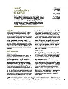
FIGURE 1. Left: Plasma wave excitation in the nonlinear regime: (a) electron density n/n0 , (b) axial electric field Ez /E0 , (c) transverse electric field Er /E0 . Laser with a0 = 3.5, k p r0 = 5, and k p L = 1 is propagating to the right [centered at k p (z − ct) = 0]. Positron acceleration and focusing only possible in electron density spike at back of the cavity k p (z − ct) ≃ −6. Right: Plasma wave excitation in the quasi-linear regime: (d) electron density n/n0 , (e) axial electric field Ez /E0 , (f) transverse electric field Er /E0 . Laser with a0 = 1, k p r0 = 5, and k p L = 1 is propagating to the right [centered at k p (z − ct) = 0]. Nearly symmetric regions of focusing and acceleration for both electrons and positrons in quasi-linear regime. Numerical modeling shown in (a)–(f) performed using INF&RNO [19].
drivers. This nonlinear regime has several attractive features for electron acceleration. In particular, in the cavity, the focusing forces are linear (determined by the ion density) (Er − Bθ )/E0 = k p r/2, and the accelerating forces are transversely uniform Ez /E0 = k p ζ /2. The condition for cavity formation, referred to as the blow-out regime, is that the beam density be greater than the plasma density nb > n0 , the beam dimensions be less than a skin depth k p rb < 1 and k p L < 1. It was later discussed [17, 18] that this cavitated regime can also be accessed with a laser-driver, and for laser drivers is referred to as the bubble regime. The condition to enter this regime using a laser driver is that the nonlinear 2 2 1/2 ∼ n/n − 1, or, for a Gaussian ponderomotive force balance the space-charge force of the bare ions k−2 0 p ∇⊥ (1 + a ) 2 2 1/2 2 2 pulse profile, a /(1 + a ) ∼ k p r0 /4. Therefore, for laser-drivers, by increasing the laser intensity, the nonlinear bubble regime can be accessed. Note that one can also enter this regime by using a sufficiently tight laser focus to produce a large transverse ponderomotive force. Figure 1(a)–(c) shows a laser-plasma accelerator entering the bubble regime. As the laser intensity increases, the regions of focusing and defocusing of electrons become highly asymmetric. This is shown in Fig. 1(c). This asymmetry in the wake may be an issue if acceleration of positrons are desired for high energy physics applications. Positrons can be accelerated and focused on the electron density spike at the back of the cavity [cf. Fig. 1(a)], where the attractive properties of the nonlinear bubble regime are lost. As the plasma wave becomes more nonlinear, the phase region where positron acceleration and focusing is possible becomes narrower. By reducing the laser intensity, the laser-plasma accelerator enters the quasi-linear regime, as shown in Fig. 1(d)– (f). In the quasi-linear regime the fields are nearly symmetric for electrons and positron acceleration and focusing. In addition there is no self-trapping, stable laser propagation can be achieved in a plasma channel, and the transverse focusing forces can be controlled via the transverse laser intensity profile as discussed above. Accessing the linear regime of beam-driven plasma accelerators (to facilitate positron acceleration) requires Ez√ /E0 . 1. Assuming a bi-Gaussian electron beam with k p rb ≪ 1, the solution to Eq. (2) is Ez /E0 ≈ 2π (nb /n0 )(k p L) exp (−k2p L2 /2)(k p rb )2 ln(1/k p rb ) ∝ Nb n1/2 . Hence operating in the linear regime re-
62
quires low plasma density or low beam charge. For fixed bunch charge (i.e., fixed driver energy to be transferred to a witness bunch), operating in the linear regime requires low plasma densities. Lower plasma densities result in smaller accelerating gradients Ez = 2E0 k p re Nb ln(1/k p rb ) ∝ Nb /L2 ∝ Nb n ∝ 1/Nb . In the nonlinear blow-out regime of PWFA, particle-in-cell simulations have shown [20] that the linear beam length scaling for the accelerating gradient holds in the nonlinear regime, namely Ez ∝ Nb /L2 ∝ Nb n, assuming the resonant √ condition k p L ≈ 2 (i.e., optimizing the beam length). The operational density in the nonlinear blow-out regime is determined simply by the availability of short drive bunches, and the size of the accelerating field is proportional to the plasma density. For example, given a 30 µ m beam length, indicates one should operate at ∼ 1017 cm−3 to maximize the accelerating gradient. The energy gain in a beam-driven plasma wave is given by the transformer ratio: R = ∆γ /γdrive , where ∆γ is the energy gained by an electron at the peak of the accelerating field and γdrive is the energy in the drive bunch. Under general considerations [21], R ≤ 2 for plasma waves driven by symmetric beams. Higher transformer ratios may be achieved by using asymmetric beams to drive the wake. In particular, transformer ratios with R > 2 can be achieved using a long (k p L ≫ 1), ramped beam (i.e., triangular bunch with low density at the head), or, equivalently, a train of bunches with increasing charge. A higher transformer ratio enables a more compact accelerator via the use of lower energy drive beams (potentially produced from smaller conventional accelerators). Appropriately shaped ramped bunches have been produced experimentally [22], as well as ramped bunch trains [23]. Experiments using a ramped bunch train in a dielectric-loaded wakefield accelerator have demonstrated high transformer ratios [24]. One limitation with using long beams for high transformer ratios, is that long beams are subject to instabilities, and, in particular, the electron-hose instability [25, 26]. The growth rate of the electron-hose instability scales as −1/6 Γhose ∼ γb (ω pt)1/3 (k p L)2/3 , indicating that the most effective way to suppress hosing is to reduce the bunch length. In a laser-plasma accelerator, the energy gain is limited by the laser energy depletion length. The laser depletion length [27], for fixed laser intensity, scales as Ld ∝ n−3/2 . Since, for fixed intensity, the accelerating field of the plasma wave scales as Ez ∼ E0 ∝ n1/2 , the energy gain in a single laser-plasma accelerator scales with plasma density as ∆γ ∼ Ez Ld ∝ n−1 . Achieving higher energy gains in a single laser-plasma accelerator requires going to lower density, lower gradient, and longer interaction lengths. Present laser-plasma accelerator experiments typically rely on selftrapping of plasma electrons. The self-trapping threshold is determined by the phase velocity of the plasma wave [28]. In contrast to beam-driven plasma waves, the phase velocity of the laser-driven plasma wave is a function of plasma density, and for fixed intensity, the Lorentz factor of the phase velocity scales as γ p ≈ ω0 /ω p ∝ n−1/2 , where ω0 = 2π c/λ0 is the laser frequency. Hence, to achieve high energy gains requires operating at low plasma density, and, as a consequence of the increased phase velocity, using some form of triggered injection. Several methods of trigged injection are actively being explored, such as colliding pulse injection [29, 30], using plasma density gradients [31, 32], and ionization injection [33–36].
DRIVER PROPAGATION AND COUPLING Plasma-based acceleration can be limited by the laser-plasma or beam-plasma interaction length. This interaction length may be set by either the characteristic propagation distance of the driver, or driver-plasma instabilities. For a beam-driver, the characteristic scale length for beam evolution is the beta function β = γ rb2 /εn , over which the beam diverges. In the nonlinear blow-out regime, the body of the beam may be self-guided in the cavity, but the head of the beam (outside the cavity) will continue to diverge, leading to beam head erosion. The rate of head erosion will be proportional to the beam emittance. A straightforward solution to extending the beam-plasma interaction length is to use a low emittance beam. For example, using a beam with a geometric emittance of εn /γb = 10−10 m-rad and a 10 µ m beam radius, yields β = 1 m. A tightly focused laser diffracts, and the length over which the laser diffracts is the Rayleigh range ZR = π r02 /λ0 , where r0 is the laser spot size and λ0 is the laser wavelength. In the nonlinear bubble regime, the body of the laser may be guided in the cavity, but the head of the laser will be outside the cavity and will continue to diffract, leading to erosion of the head of the laser. The Rayleigh range is typically the shortest length scale for laser evolution. For example, ZR = 2 mm for r0 = 25 µ m and λ0 = 1 µ m. The geometric emittance of the photon beam is fixed by the laser wavelength, and therefore some form of external guiding must be employed. Preformed plasma density channels (i.e., tailoring the transverse plasma density profile such that there is a density minimum on axis) have been successfully demonstrated as an effective mechanism for guiding a laser pulse [37–39]. Hydrogen capillary discharge waveguides [40] have been used to generate long (few cm), low density (few 1018 cm−3 ) plasma channels suitable for producing
63
high-energy beams in a laser-plasma accelerator [7, 41]. The phase velocity of the plasma wave is approximately equal to the driver propagation velocity. The velocity of the beam driver is typically ultra-relativistic, e.g., γb = γ p ∼ 104. These large phase velocities have several advantages: no trapping of background plasma electrons (dark current free), negligible slippage between the drive and a witness bunch, and reduction of beam-plasma instabilities (i.e., a stiff driver). For laser-driven plasma waves the phase velocity is rather low. The laser driver propagation velocity is approximately the driver velocity, and using λ0 = 1 µ m wavelength in typical plasma densities n ∼ 1017–1019 cm−3 , γg ≈ γ p ∼ 10–100. This relatively low plasma wave phase velocity can allow trapping of background plasma electrons as discussed in the previous section. The low phase velocity also results in slippage between the plasma wave and the beam. The distance over which the beam slips from an accelerating to a deceleration region of the plasma wave, or dephasing length, is Ld ph ∼ λ p γ p2 . This slippage may limit the energy gain ∆γ ∝ γ p2 . One solution to slippage is to taper the plasma density longitudinally [42, 43], i.e., on the scale of the dephasing length, slowly increase the plasma density, thereby decreasing the plasma wavelength λ p ∝ n−1/2 and maintaining the phase of the beam in the plasma wave. By tailoring the plasma both transversely (for laser guiding) and longitudinally (for beam-wake phase-locking) both diffraction and dephasing may be overcome. In this case the single stage energy gain in a laser-plasma accelerator is limited by laser energy depletion. For fixed driver energy, increasing the beam energy requires staging plasma accelerators. The total size of the accelerator will be determined not only by the length of the plasma accelerator, but also by the distance to couple a new driver into subsequent plasma accelerator stages. Consider an accelerator stage consisting of the plasma length and the driver-coupling distance: Lstage = Lcouple + Lplasma . The total length of the accelerator will be Ltotal = Nstage Lstage = (Wfinal /Wstage )(Lcouple + Lplasma ), where Wfinal is the required final energy and Wstage is the energy gain per stage (approximately the driver energy). Minimizing the accelerator length and maximizing the geometric gradient requires Lcouple . Lplasma . For example, coupling a ∼ 25 GeV beam into a plasma while preserving beam quality, requires ∼ 100 m. Coupling tens of J of laser energy, while avoiding damage to optics, requires several meters using conventional focusing optics. A laser-driver may also be in-coupled using a plasma mirror [44, 45]. A plasma mirror uses an overcritical plasma created on the surface of a renewable material (tape or liquid jet) by the foot of an intense laser pulse to reflect the body of the laser pulse. Using a plasma mirror, laser-driver in-coupling may be achieved in . 10 cm. Using laser-drivers offers the potential of ultrahigh average or geometric gradients of the staged plasma accelerator [9, 10]. Note that given a driver of sufficient energy, coupling additional drivers would be unnecessary. For example, in the case of a high-energy beam-driven accelerator, a proton beam could be accelerated to TeV energies in a conventional circular accelerator, and used to drive a plasma wave, transferring a large fraction of its energy to a plasma wave in a single stage [46]. In the case of a laser-driven plasma accelerator, even with a sufficiently high energy laser driver, staging is desirable to maintain high accelerating gradient. As discussed above, obtaining high energy in a single laser-plasma accelerator requires operating at low plasma density Wstage ∝ 1/n, with longer plasmas Lplasma ∝ n3/2 and lower accelerating gradients Ez ∝ n1/2 . A more compact accelerator design (with higher average gradient) would use multiple highdensity, ultrahigh gradient laser-plasma accelerator stages [10].
SUMMARY AND CONCLUSIONS In this proceedings paper we have discussed some of the similarities and differences between plasma acceleration using laser drivers or particle beam drivers. Although laser-driven and beam-driven plasma acceleration are equivalent in some aspects, there are some fundamental differences that arise from the physics of the excitation mechanisms. For the case of the laser drivers, excitation is from the nonlinear ponderomotive force, and for beam drivers, from the space-charge force. The different physical mechanisms, as well as the typical characteristics of the drivers, have important implications for the design of plasma-based accelerators. The field structure of the plasma wave can be strongly dependent on the driver. For example, in the linear regime, the fields of a tightly focused electron beam extend at least a plasma skin depth, independent of the transverse bunch structure, and therefore shaping the transverse fields by shaping the drive bunch is problematic. In contrast, the transverse fields of the laser-driven plasma wave are determined by the local transverse gradient in laser intensity, and therefore the transverse fields (and the focusing forces) can be controlled by controlling the transverse laser intensity profile. The nonlinear cavitated regime can be accessed by either a beam driver or a laser driver. In this regime the phase
64
region where positron acceleration is possible is greatly reduced. For beam-drivers of fixed charge, operating in the linear regime requires using low density (and consequently low accelerating gradient). The accelerating gradient of the beam-driven plasma wave scales as Ez ∝ 1/L2 , and, hence, the operational density is determined by the availability of short particle beams. The operation density for laser-driven plasma waves is determined by the laser pulse energy and laser depletion length. In practice the phase velocity of the beam driven plasma wave is typically much larger than the phase velocity of the laser-driven wave γb ≫ γg . One consequence is the potential for self-trapping of background plasma electrons in laserdriven plasma accelerators. Another consequence is slippage between a relativistic witness beam and a laser-driven plasma wave. This slippage can limit the energy gain, and plasma tapering may be used to overcome this limitation. In this paper, we have discussed PWFAs driven by electron beams. Plasma waves may also be excited by positrons, where the driver attracts electrons in an initially neutral plasma creating a space-charge oscillation [47]. Proton beams are also being actively considered for plasma wave excitation [46]. The challenge for proton beam drivers is generating short (on the order of the plasma period) proton beams to resonantly excite large plasma waves. PWFAs driven by electron beams have received the most attention because of the availability of high average and peak power electron beams for drivers. Minimizing the driver coupling length is also essential to staged plasma accelerator design. In a multi-stage plasma accelerator the size of the machine (and the average/geometric gradient) will be determined by the distance to couple a fresh driver into subsequent stages. Lasers offer the possibility of short coupling distances, commensurate with the plasma length, enabling ultra-high average/geometric gradients for the multi-stage plasma accelerator. In this paper we have also focused on accelerator properties arising from plasma physics, and not addressed the driver technology. It should be noted that high-power, high efficiency, high repetition rate charged particle beams are presently available from conventional accelerator systems. The footprint of such a conventional accelerator system (e.g., using S-band linacs) is large. The footprint may be reduced, for example, by using X-band technology to accelerate the drive beams and beam shaping to yield a high transformer ratio. Significant R&D is required to realize high transformer ratios (R > 2) with stable beam propagation in beam-driven plasma accelerators. Presently, the laser technology exists to deliver intense, short laser pulses, e.g., tens of J of laser energy in tens of fs (i.e., PW peak power laser systems), operating at 1-10 Hz. Such a PW laser system occupies a small footprint (