Design Considerations for Stand-alone Haptic Interfaces Communicating via UDP Protocol Ryan M. Traylor,1 Daniel Wilhelm,1 Bernard D. Adelstein2 and Hong Z. Tan1 1 Haptic Interface Research Laboratory, Purdue University, West Lafayette, IN 47906 {traylorr, dwilhelm, hongtan}@purdue.edu 2 Human Factors Division, NASA Ames Research Center, Moffett Field, CA 94035
[email protected] Abstract This work was motivated by the need for high-speed communication between a stand-alone haptic interface and an external computer running haptic rendering algorithms. This paper describes our recent work with User Datagram Protocol (UDP) over Ethernet as a communication channel between a remote computer and a custom embedded controller built for a fingerscale 3 DOF force-feedback haptic interface (the 3DOF ministick). The results and observations from three experiments are contrasted with theoretical timing models in order to isolate potential problems and verify predicted models. Details of the controller hardware that enabled a haptic update rate of 3800 Hz are provided. Information that may reduce development time for other systems requiring Ethernet communication is also presented.
1. Introduction As haptics technology becomes more mature, there has been much work in recent years toward developing stand-alone and plug-and-play haptic interfaces. Instead of using proprietary ISA or PCI bus cards to interface a haptic interface to a PC, the trend is to use the parallel or USB 2.0 port for inter-device communication. Recently, we have experimented with User Datagram Protocol (UDP) over Ethernet for a 3DOF force-feedback hardware platform, and succeeded in a haptic update rate of 3800 Hz. We employ custom embedded controller hardware capable of both controlling a variety of different haptic interfaces and communicating via Ethernet with remote computers. Rather than focusing on the embedded controller, this paper examines Ethernet communication and more specifically, the pitfalls encountered while
implementing and utilizing the protocol to control haptic interfaces. Several different types of communication protocols are used in COTS (commercial off-the-shelf) haptic interfaces being marketed today. For instance, the Delta Haptic Device [1] utilizes a proprietary PCI interface card, the Phantom Desktop [2] a parallel port, the Omega Haptic Device [1] USB 2.0 protocol, while the Phantom Omni [3] uses IEEE-1394 FireWire®. Another widely available computer communication protocol, Ethernet, can potentially be included, even though it is not widely used for controlling haptic interfaces. Each of these communication protocols has its advantages and disadvantages. Among the various metrics for comparing and contrasting between protocols are bandwidth, design complexity, protocol efficiency, and scalability. With the possible exception of the parallel port, each protocol offers enough bandwidth to support communication with haptic interfaces running at update rates requiring the transfer of several thousand data frames per second. The design complexity eliminates a PCI interface card since developing a custom circuit board to interface with a computer’s bus is rather complicated and time consuming. This leaves FireWire®, USB, and Ethernet as viable candidates. By far the most scalable is Ethernet communication because many haptic devices and computers can be linked together on a single Ethernet network. Many devices such as Ethernet switches and routers are commercially available to link the embedded controller with one or more remote computers locally or globally. Of the many available Ethernet protocols, the most commonly used are Address Resolution Protocol (ARP), Internet Control Message Protocol (ICMP), Transmission Control Protocol (TCP), and UDP. Of these four, UDP and TCP are best suited to transfer blocks of data between the embedded controller and a remote computer due to the protocol’s structures. TCP
guarantees the delivery of each packet at the expense of requiring that an acknowledgement packet be received and processed within a certain amount of time after the initial transmission. While UDP does not require this extra acknowledgment packet, the embedded controller would never know if a packet were lost or dropped for any reason before reaching the remote computer. Packet dropping associated with UDP, however, does not present a major problem for the following reasons. First, it is assumed that the controller will be interfaced with a remote computer through either a direct crossover cable connection or a switched connection on a local area network. In this case, it is easier to identify where and why packets might be dropped. The computer or the embedded controller could potentially drop packets if the communication rate becomes too high for either to handle. If the packets were traveling over a larger network such as the Internet, routers and nondeterministic network traffic increases the possibility that a packet might be dropped or lost all together. Second, we can control somewhat deterministically the communication bandwidth required between the controller and computer by adjusting the haptic update rate. The haptic update rate is dictated by how often the haptic device transmits position data to and receives actuator commands from a remote computer. Thus, the bandwidth required over an Ethernet communication channel is directly proportional to the haptic update rate. Assuming that the bandwidth consumed by average traffic on a local network connection is minor compared to the overall bandwidth required to sustain the necessary haptic update rates, the update rate can be tuned such that it is not overwhelming the embedded controller or computer. Since the computer’s processor is capable of performing operations at least two orders of magnitude faster than the particular microcontroller used in the current embedded controller design, it is assumed for the purposes of this design that the embedded controller will determine the limit on the maximum communication bandwidth. Third, even in the rare event that a few packets out of the many thousands streaming over the network are lost, it may not cause any noticeable change in the controller behavior on the average. For instance, if a packet is dropped, the controller will hold the last command until the next packet arrives. As long as the force command does not change significantly until the next packet arrives, the user should not notice any effect. Another advantage of using UDP is its eight byte fixedlength header as opposed to TCP’s variable header length (>20 Bytes). In short, sending smaller packets saves time. For all of these reasons, UDP was chosen
as the protocol used to transfer information between the embedded controller and remote computers. The remainder of this paper is organized as follows. We discuss the embedded controller and the 3-DOF force-feedback haptic device in Section 2. Three experiments involving different modes of utilizing UDP are reported in Section 3. The last section offers recommendations for using UDP communication protocols with stand-alone haptic interfaces.
2. Hardware platform 2.1. Embedded controller specifications The embedded controller is based on an 8-bit ATMEGA128 [4] microcontroller running at 16 MHz. It is wired to a Packet Whacker [5] 10 Mbps halfduplex Ethernet controller card through the microcontroller’s common communication bus. An extremely streamlined UDP/IP Ethernet stack is implemented in the firmware stored onboard the microcontroller. The Ethernet stack is simply the portion of the firmware that is in charge of taking a packet from the Ethernet controller, then decoding, managing, and processing it based on the packet’s individual protocol. Our stack is loosely based on Fred Eady’s full TCP/IP stack [6], with modifications made for the use of static IP headers, but without checksum calculations or TCP protocol management. It is assumed for our design that the controller will simply take raw position data from sensors, send them to the remote computer, and then receive data in return that contain the instantaneous commands to the actuators. The remote computer will be in charge of the calculations for updating the virtual environment and for computing actuator commands based on the predefined kinematics of the haptic interface. Consequently, two 64-Byte Ethernet UDP communications take place (one transmission and one reception) during each haptic update period. With haptic update rates potentially exceeding 1000 Hz, it is evident why streamlining the stack is so important. Specifically, it allows for higher haptic update rates, higher immunity to livelock conditions even in the presence of potential network traffic, and it leaves sufficient time for computationally intensive calculations taking place on the remote computer.
2.2. The 3-DOF ministick The haptic interface housing the embedded controller is a point-force interaction-type device (i.e., a joystick) that couples three rotationally actuated degrees of freedom to 3-DOF endpoint force and motion. The joystick’s design is based on a unique fully-parallel, 10
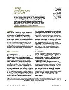
rigid link, 12 revolute joint spatial architecture [7] that affords the structural stiffness typically associated with parallel mechanisms, but with the range of motion approaching that of serial linkages. Importantly, from a computational standpoint, both the forward and inverse kinematics for this device can be expressed and solved in closed form [8]. The device’s parallel linkage is composed of three five-bar loops. Its two spherical loops include the three brushless motor actuators and the base plate onto which the motors are mounted. Its single planar loop is effectively an extendable parallelogram arm that pivots about the shared center of the two spherical loops. In the current finger-scale implementations [9-10], the parallelogram’s upper and lower arm links are each 50.8 mm (2 in) in length. The device’s usable, interference-free workspace is enclosed within the hemispherical volume bounded by singularities in the plane of the actuator axes and the radius of maximum arm reach [8] and occupies a region roughly 9 cm by 9 cm by 6 cm (see Figure 1). In addition to reducing inertia and mass by mounting its three actuators on its base plate, the mechanism is passively balanced through individual link shape design and alloy selection [10]. The passive mass balance allows actuator effort to be allocated completely to endpoint simulation force production and not the support of individual link weight against gravity.
processes the commands, and then sends a packet of position readings back to the computer. Since the embedded controller in this case relies on the computer to initiate and sustain communication, this mode of operation is called the client mode. For this and all subsequent experiments, the remote computer is equipped with a 2.8 GHz Pentium processor and 3Com 3C940 Gigabit Ethernet card and running the Windows XP Professional SP1 operating system. 3.1.1. Experiment configuration With the embedded controller in client mode, the remote computer was programmed to send off one “initialization” packet to start off the communication, then simply wait until receiving a reply from the controller to transmit another packet. In this scenario, one would expect to observe the maximum round trip frequency (the highest haptic update rate) obtainable by the system because both the controller and computer simply wait for the other to respond, then immediately reply back, thereby wasting no time. 3.1.2. Results and discussions It is straightforward to compute the theoretical maximum round trip frequency (RTF). One merely needs to take the inverse of all the time spent by the computer and controller processing, sending, and receiving a packet, and the travel time for each packet from source to destination. At 10 Mbits/s, the transmission time for one 64-byte UDP packet plus 64 preamble bits and four checksum bytes is:
1s ≈ 61 µs 7 10 bits
(1 Packet ) × 608 bits × 1 Packet
For client mode operation, the controller spends 230 µs receiving, processing, and sending a packet. The computer spends about 155 µs doing the same. Therefore, the maximum theoretical RTF is:
1
(155 µs + 61µs + 230 µs + 61 µs ) Figure 1: The 3-DOF ministick.
3. Experiments with UDP 3.1. Client mode In this experiment, the embedded controller’s firmware is modified so that it waits to receive a packet of actuator commands from the remote computer,
= 1972 Hz
The experimental measurements show that a RTF of about 2000 Hz was sustained throughout the course of each trial, validating the theoretical maximum RTF. The RTF was computed in software by using the Microsoft Windows high resolution performance counter to measure the time between each round trip. The round trip times were averaged over a group of 100 round trips.
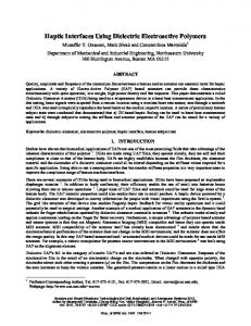
However, when two “initialization” packets were sent at the beginning of one of the trials, the result was an initial update rate close to 3800 Hz which lasted for a seemingly random period of time (on the average around several seconds), then a sudden drop to a sustained rate of about 2000 Hz. Further tests showed that this occurrence was repeatable. How an update rate exceeding the 1972 Hz theoretical maximum could be sustained for even a short period of time is addressed by the timing diagrams in Figures 2 and 3. Figure 2 shows a simulation of the client mode operating at the theoretical maximum update rate of 1972 Hz. The “high” portion of the pulses occurs when the corresponding device is active. The “R” and “T” labels respectively indicate from the embedded controller’s perspective whether the packet is being received or transmitted. The same labeling convention is used for all subsequent timing diagrams in this paper. One can verify from the recorded data that the maximum update rate has been reached by observing in the figure that there is no delay between the time the controller transmits a packet to the computer and the time the computer processes that packet and then replies back to the controller. However, something different happens when two “initialization” packets are sent to start the communication as simulated in the timing diagram of Figure 3.
Figure 2: Timing diagram for client mode operation running at 1972 Hz.
Figure 3: Timing diagram for client mode operation running at 3800 Hz. One can see immediately that it is indeed possible to achieve an update rate of 3800 Hz, however, there is a tradeoff. The packet containing the actuator commands is no longer sent by the computer in response to the packet loaded with position data by the controller in the previous haptic update period. Instead, it is from the packet sent one sample period prior to the previous update period. Essentially, the update rate is almost twice as high as the previously computed theoretical maximum. However, the delay between when the positions are sent from the controller and the time when the actuators are updated in response to those positions is roughly the same. We conjecture that the return of the communication pattern back to that of Figure 2 occurs when a packet is somehow lost. This is most likely the cause for the sudden and seemingly random drop in update rate from around 3800 Hz to around 2000 Hz as observed in the experiment. No dropped packets were detected while the system was running at 2000 Hz based on the observation that the system did not stall at this rate. The loss of a second packet would mean that either the embedded controller will not receive a packet, in which case it will never send a reply, or the remote computer will not receive a packet, in which case it will never send a reply. Both cases result in stalled operation. A special version of software was written, which commanded the remote computer to send an extra packet to the embedded controller if it detected that the update rate fell from 3800 Hz to 2000 Hz. The result was a system that ran with a sustained rate of 3800 Hz, which supports the packet dropping hypothesis. The main conclusions from this experiment are that it is theoretically possible to push the update rates of the system up to ~3800 Hz under certain conditions, and that the embedded controller is the limiting factor
in determining the maximum update rate because, as shown in Figure 3, its processor running very close to full time at that rate.
3.2. Server mode In this experiment, the embedded controller’s firmware transmits successive position data packets at a fixed interval, then processes the actuator command packets sent in response by the remote computer as they arrive. Since the embedded controller initiates and sustains communication with the remote computer in this case, this mode of operation is called the server mode. 3.2.1. Experiment configuration The embedded controller was set to server mode and given a certain fixed update rate at which to transmit position packets. The remote computer was then programmed to simply wait until a position packet arrived, process the data, and then immediately send back an actuator control packet to the controller. 3.2.2. Results and discussions Based on the results of the client mode experiments, it was expected that the update rate in server mode should easily approach 1972 Hz and should be able to push well into the 3000 Hz range, assuming similar processing times for the embedded controller and computer in both modes. The actual observations, however, proved otherwise. Before discussing the results in detail, the slight change in processing times of the controller and computer in server mode should be noted. The embedded controller no longer spends a single chunk of time receiving, processing, and sending a response to the remote computer as it did in the client mode operation. In the server mode, data processing is split in two, with parts associated with the transmit and receive functions, as shown in Figure 4. The controller spends 128 µs sending a packet and 109 µs receiving a packet. The computer processing time is still 155 µs, but the response packet is actually sent only 80 µs into the 155 µs window, instead of at the end of the 155 µs processing time. These changes have the result of slightly increasing the theoretical maximum update rate. The embedded controller can potentially try to send packets faster than it or the computer can manage. To analyze the data traveling over the Ethernet line to detect such problems, Ethereal [11], a “packet sniffer” program, was employed to monitor, record, and timestamp Ethernet packets traveling over the remote computer-embedded controller network. If the packet sniffer were to observe any packets out of order or
more transmissions by the embedded controller than receptions by the remote computer, then there would be an indication that the update rate was set to too high. When the update rate exceeded ~2300 Hz, the Ethereal data capture showed that packets “doubled up” in the computer. Instead of the computer replying back to each position packet individually, it actually received two packets, then replied to them both at once. This observation leads one to believe that the remote computer may really be the bottleneck in the system, since the evidence seems to point to the computer falling behind while servicing incoming packets. The same phenomenon occurred during the client mode operation as well. However, the packet sniffer was not used during the client-mode experiments as it was deemed that the system would automatically limit its update rate to meet the constraints of the slowest device. It is helpful to consult the timing diagrams for the server mode operations, shown in Figure 4 for the relatively conservative update rate of 1972 Hz. For comparison, Figure 5 shows the server mode timing diagram for a haptic update rate of 3800 Hz. Neither timing diagram shows any immediate visual sign of conflict such as an unachievable processing workload, or missed packets.
Figure 4: Timing diagram for server mode operation running at 1972 Hz.
fast for the computer to handle. Increasing the interrupt rate limit to 10,000 interrupts per second enabled the haptic update rate to increase to around 3800 Hz without the problems associated with packet buffering. Therefore, it is clear that the embedded controller again becomes the bottleneck once the interrupt moderation rate is increased to a sufficient level.
3.3. Distributed mode
Figure 5: Timing diagram for server mode operation running at 3800 Hz. In order to understand and resolve why the packets seem to be buffered and serviced two at a time, one must understand the interaction between the computer’s network card and its operating system. The network card lets the operating system know when a packet has been received or transmitted by issuing an interrupt to the processor. Upon receiving the interrupt, the operating system makes an appropriate response to handle the incoming or outgoing data, which consumes a small amount of time. As more and more packets are received and/or transmitted, those small bits of time add up and soon the computer starts to become sluggish. The remote computer in all experiments used a 1 Gbps Ethernet card. However, if that bandwidth was truly approached, the interrupts associated with the large number of packets being transferred would cause the system to grind to a halt. Consequently, a feature called “interrupt moderation” is employed with Gigabit Ethernet cards to limit the allowable rate of interrupts per second. If the interrupt rate limit is exceeded, the network card simply buffers the events and presents them all during the next single interrupt. The maximum interrupt rate limit on the computer used in these experiments was originally set to the default of 5000 interrupts per second. The background interrupts that the card produces due to random network traffic was found to hover around 400 interrupts per second using the Microsoft Windows Performance Monitor. Therefore, when the haptic update rate reached 2300 Hz, there were 4600 interrupts per second (one interrupt for each packet transmission and reception) due to the experiment. Those interrupts combined with the background interrupts actually reached the interrupt rate limit, which caused the incoming packets to be buffered and appeared as if they were coming in too
Although the embedded controller was proved to be the limiting factor in determining the maximum update rate of this system, it is feasible that in the future a different embedded system equipped with a much faster processor and Ethernet interface could actually cause the computer to be the limiting factor. It is also conceivable that a very complicated virtual environment could cause the computer to take much longer than the 155 µs allotted in both the client-mode and server-mode experiments thereby causing the computer to become the limiting factor. A novel way to alleviate these potential problems is by distributing the workload of processing the Ethernet packets among more than one computer using the scalability afforded to the system by Ethernet communication protocol. This scalability allows for the straightforward addition of more remote computers on the network, which all possess the ability to communicate directly with, and thus control, the embedded controller. Due to the fact that in this configuration the packets are distributed for processing over more than one computer, this mode of operation is called the distributed mode. 3.3.1. Experiment configuration Two remote computers and one embedded controller are linked together over Ethernet through the use of a common Ethernet switch. The embedded controller is programmed to send its first position packet to the first remote computer, then one haptic update period later, a second position packet is sent to the second remote computer. This process repeats itself such that all odd position packets are sent to the first computer and all even position packets are sent to the second computer for processing. The embedded controller receives and processes the actuator command packets as they are received from the remote computers. In this scheme, the desired haptic update rate is realized, while only requiring half of the processing power from each remote computer as from the single computer used in the server mode experiments. The actual configuration of the experiment is illustrated in Figure 6.
Figure 6: Experiment configuration for distributed mode operation. 3.3.2. Results and discussions A timing diagram for an implementation of the distributed mode with a haptic update rate of 3200 Hz utilizing two computers is shown in Figure 7. Detailed records of network traffic captured by Ethereal were examined to verify that the real-world model behaved as expected from the timing diagram.
significantly increase the maximum achievable haptic update rate include using a faster microcontroller, a 100 Mbps Ethernet controller with full-duplex capabilities, and a more streamlined Ethernet stack. Several points need to be considered during the design and evaluation process. It is important that a streamlined Ethernet stack be implemented on an embedded controller with modest processing power as it will tend be the limiting factor for the overall haptic update rate. Developing a model and simulations using expected timing parameters and comparing these with real-world observations of the system is essential. Using real-time packet sniffers such as Ethereal is highly recommended to record and observe what data are really traveling over the network, because it may not be what is expected even if other observations indicate otherwise. Finally, special attention must be paid to the interrupt moderation feature and its effects on the true haptic update rate as the use of Gigabit Ethernet cards becomes more prevalent.
Acknowledgments This work was supported in part by a National Science Foundation award under Grant 0098443-IIS, and in part by NASA under award no. NCC 2-1363. The mechanical hardware for the 3-DOF ministick was purchased from UC Berkeley.
References [1] Force Dimension – Product Information. 29 Aug. 2004. 12 Nov. 2004. [2] Products: Phantom Desktop. Sensable Technologies. 12 Nov. 2004.
Figure 7: Timing diagram for distributed mode operation running at 3200 Hz.
4. Conclusion UDP protocol over Ethernet has been shown to be a viable method of communication between haptic devices and remote computers. A haptic update rate of 3800 Hz was shown to be an approximate upper bound for reliable operation in our system. Because this bound was found to be dictated by the speed and efficiency of the embedded controller used in our design, it is by no means a global upper bound for communication with haptic devices using UDP. Ways to modify the embedded controller in order to
[3] Products: Phantom Omni. Sensable Technologies. 12 Nov. 2004. [4] Atmel Corporation. “Atmel ATMEGA128(L).” Datasheets. Available: Nov. 2004. [5] Eady, Fred. Introducing the Packet Whacker, Part 1: Hitching a Ride on the PICDEM.NET. Circuit Cellar Online. Oct. 2001: 3-7. Available: [6] Eady, Fred. Introducing the Packet Whacker, Part 2: Setting a Course with Code. Circuit Cellar Online. Nov. 2001: 4-16. Available: [7] Adelstein, B.D. (1998) Three Degree of Freedom Parallel Mechanical Linkage, US Patent 5,816,105, Oct. 6, 1998.
[8] Adelstein, B.D. Ho, P., & Kazerooni, H. (1996) Kinematic design of a three degree of freedom parallel hand controller mechanism. Proceedings of the 5th International Symposium on Haptic Interfaces for Virtual Environment and Teleoperator Systems, DSCVol. 58, American Society of Mechanical Engineers, New York, pp. 539-546. [9] Chung, R., Adelstein, B.D. , & Kazerooni, H. (2001) Electronic hardware for improved haptic interface performance. In M. McLauglin (ed.), Touch in Virtual Environments, Prentice-Hall, pp. 73-96. [10] Steger, R., Lin, K., Adelstein, B.D., & Kazerooni, H. (2004) Design of a passively balanced spatial linkage haptic interface. Submitted to ASME J. Mech Design. [11] Ethereal: A Network Protocol Analyzer. 21 Oct. 2004. 12 Nov. 2004.