DESIGN CONSIDERATIONS FOR THE DUAL-FED DISTRIBUTED POWER AMPLIFIER. K. W. ECCLESTON Dept of Electrical Engineering National University of Singapore SINGAPORE 119260 E-mail:
[email protected] The dual-fed distributed amplifier is a variation of the conventional single-fed distributed amplifier whereby the input signal is fed to both ends of the input line using a hybrid, and signals appearing at both ends of the output line are combined using another hybrid. Such a configuration allows utilisation of output power in the backward as well as forward waves. Much of the previous work in the literature only considered small-signal analysis and small electrical spacing between FETs, and did not lend insight into the operational behaviour. This paper therefore considers the development of a design method for the dual-fed distributed power amplifier with large electrical spacing. The simulations demonstrate optimum loadlines are achieved for all FETs and that all FET output power is utilised.
1
Introduction
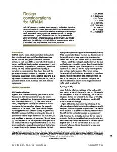
The conventional distributed amplifier has proven highly successful for small-signal broadband applications. However, its success in power applications has been limited for a number of fundamental reasons such as: uneven output power distribution among the FETs [1], and output power wastage in the back-ward waves [2]. The first problem results in under utilisation of some of the FETs, whilst the second problem results in lowered efficiency due to wasted output power. Typically at microwave frequencies, the FETs nearest the output terminal contributes the most power whilst the FETs farthest away contributes minimal. Over some frequency ranges, some of the FETs sink rather than source power [1]. Methods such as output line tapering [2] may be used to minimise power in the backward waves and circuit optimisation [3] may be used to improve the output power distribution among the FETs. However, their success is limited as the problems they aim to cure are fundamental in nature. A variation to the distributed amplifier topology, the dual-fed distributed amplifier, has been proposed as a means to utilise output power in both the backward and forward waves [4]. The circuit diagram of the modified distributed amplifier is shown in Figure 1 and essentially involves a dual-feed at both the input and output lines using hybrids. Despite the promise that such feeding should provide, the previous work [4][5][6] only considered a small-signal analysis and small electrical spacing between FETs, and did not lend insight into the operational behaviour. Recent work by this author [7], which considered large electrical spacing between the FETs, determined the conditions whereby power equalisation among all the FETs can be achieved. With power equalisation it is possible to have all FETs operating into an optimum lineline. It is therefore the purpose of this work to develop design guidelines for power amplification using the dual-fed distributed amplifier based on the conclusion of the previous investigation [7].
2
Theory
For the purposes of developing design equations, the circuit shown in Figure 1 may be represented by a simplified circuit depicted in Figure 2 [7]. It has been assumed that FET input and output capacitances have been absorbed into the respective transmission lines [7] or effects neutralised by a resonant circuit. The input hybrid may be replaced by a pair of Thevenin sources representing the signals appearing at the output of the input divider. The output hybrid may be replaced by the loads seen by the output transmission line. For argument sake, we will further assume that the input and
Authorized licensed use limited to: University of Canterbury. Downloaded on November 29, 2009 at 22:14 from IEEE Xplore. Restrictions apply.
output transmission line sections are lossless, have equal length, both have effective characteristic impedance Zo and phase constant β. It will be assumed that the couplers are both matched to Zo at the frequencies of interest. Let the complex variable z (“delay variable”) equal exp(- jlβ ). The voltages and currents in Figure 2 are peak values and refer to signals and do not include dc bias. If the FETs are operated in class-A mode, and have high linearity then the drain current of the kth FET is approximately given by: I d k = Gm Vg k ...1
where Gm is the large-signal transconductance. We will assume, as many other such analyses assume, that feedback may be neglected.
Figure 1 Dual-fed distributed amplifier
Figure 2 Equivalent circuit of dual-fed distributed amplifier.
Let EinA is equal to E, and EinB equal to E exp(jφ). The gate voltage of the kth FET will consist of two components, one due to EinA, and the other due to EinB :
Vgk
=
(
E z k −1 z + z n − k e jφ 2
)
...2
and hence the drain current of the kth FET will be:
I dk
=
(
G m E z k −1 z + z n − k e jφ 2
)
...3
All drain current sources drive into a load impedance of Zo/2 and expressions for the drain voltages can however be written in terms of the drain current sources:
Vd k
=
(
Zo ... + z 2 I d k − 2 + z I d k −1 + I d k + z I d k +1 + z 2 I d + 2 + ... 2
)
...4
The point to realise is that the kth drain voltage is not solely due to the kth FET drain current but has contributions from all FET drain currents. The previous work [7] determined that z equal to –1 (spacing of 180 °) results in output power equalisation among the FETs. For n equal to 4 and setting z equal to –1 gives: Vd1 (−1) = Vd3 (−1) = − Vd 2 (−1) = − Vd 4 (−1) = − jG m E Z o 1 − e jφ ...5a
(
I d1 (−1) = I d 3 (−1) = − I d 2 (−1) = − I d 4 (−1) =
(
jGm E 1 − e jφ 2
)
)
...5b
We see that the two output voltages will be 180° out of phase, the drain voltage and current for each FET are 180° out of phase and the magnitude of their ratio is 2Zo. In other words the effective
Authorized licensed use limited to: University of Canterbury. Downloaded on November 29, 2009 at 22:14 from IEEE Xplore. Restrictions apply.
loadline resistance of each FET under this condition is 4 times the actual load resistance Zo/2. One could conclude that for (at least) even n, the loadline resistance is n times Zo/2. Figure 3 shows idealised drain i/v characteristics with an optimum class-A load trajectory overlaid. The optimum loadline resistance is given by the reciprocal of the slope of the load trajectory and equating to nZo/2 we obtain the optimum characteristic impedance of the output transmission line for n even:
Z oopt
V − VD min = 2 D max I D max n
...6
Figure 3 FET drain dc i/v characteristics
3
Design Example
We consider the design of a dual-fed distributed amplifier with a centre frequency of 10 GHz employing four FETs (n = 4), rat-race hybrids at both the input and output (hence φ is 180°). The FETs have a minimum and maximum drain voltage of 1 V and 10 V respectively, and a maximum drain current of 60 mA. The FETs were each spaced by 180° at 10 GHz so as to achieve power equalisation at 10 GHz [7]. Using (6) the optimum value of the output line characteristic impedance was found to be 75 Ω which was coupled to the 50 Ω rat-race hybrid by quarter-wave transformers. The dc gate and drain bias voltages were set to –1 V and 5.5 V respectively. The input line characteristic impedance was set to 50 Ω. The input and output of each FET was resonated using parallel resonators with Q chosen to trade-off distortion and bandwidth. The gate and drain bias voltages were fed to the FETs using the resonator inductances. Further calculations revealed that the output power of each FET would be 68 mW (18.3 dBm), and hence the total output power should be 272 mW (24.3 dBm), and the drain efficiency to be 41 %.
Parameter β b VTO α Vbi CGS0 CGD
Value 0.205 AV-2 6 AV-1 -2 V 2 V-1 0.85 V 0.41 pF 0.027 pF
Table I FET Parameters Parameter Value RG 0.6 Ω RS 1.7 Ω RD 2.0 Ω LG 0.17 nH LS 0.054 nH LD 0.12 nH CDS 0.14 pF
Parameter CRF RC VBR
Value 1 µF 500 Ω 15 V
Simulations using HP MDSTM were used to check the validity of the calculations and their corresponding assumptions. The FETs were modelled using the well known Statz-Raytheon model of which the parameters are given in Table I. At 10 GHz with an input level of 12 dBm: the load
Authorized licensed use limited to: University of Canterbury. Downloaded on November 29, 2009 at 22:14 from IEEE Xplore. Restrictions apply.
trajectories (as seen by the drain current source) were essentially optimum and identical for all FETs. Each FET sourced 18.1 dBm, and the total output power was 24.2 dBm meaning all power in the forward and backward waves was recovered. The simulation therefore confirmed the design procedure. The drain efficiency was found to be 39 %, whilst the power added efficiency was 37 %. Figure 4 shows the output voltage waveform (across 50 Ω load) whilst Figure 5 shows the smallsignal transducer gain frequency response.
Figure 4. Output voltage waveform with input power level of 12 dBm.
4
Figure 5. Small-signal transducer gain.
Conclusion
In this paper we have shown the development of a design method for the dual-fed distributed power amplifier that achieves power equalisation and optimum loadline trajectory for all FETs. For power equalisation, the spacing between the FETs must 180° at the centre frequency, and for an optimum loadline, the characteristic impedance of the output line must be 2/n times the optimum loadline resistance for the case of an even number of FETs. Simulations have demonstrated the validity of this approach. Work is continuing to improve the bandwidth and to apply the design concepts developed in this paper for MMIC realisation.
References [1] J. L. B. Walker, "Some Observations on the Design and Performance of Distributed Amplifiers", IEEE T. on MTT, 40(1), Jan 1992, pp 164 - 168. [2] G. D Vendelin, et al, Microwave Circuit Design Using Linear and Nonlinear Techniques, John Wiley, 1990, p 350 - 369. [3] M. Campovecchio, et al, "Large Signal Design Method of Distributed Power Amplifiers Applied to a 2-18GHz GaAs Chip Exhibiting High Power Density Performances", Int. J. of Microwave and MMW CAE, 6(4), 1996, pp 259 - 269. [4] C. S. Aitchison, et al, "The Dual-Fed Distributed Amplifier", 1988 IEEE Int. Microwave Symp., MTT-S, pp 911 - 914. [5] S. D'Augustino & C. Paoloni, "Power Distributed Amplifier With Input-Output Combiners", Microwave and Optical Tech. Letters, 7(7), May 1994, pp 312 - 315. [6] I. A. Botterill & C. S. Aitchison, “Effect of hybrids on gain performance of dual-fed distributed amplfiers”, Electronics Letters, 30(13), 23 June 1994, pp 1067 – 1068. [7] K. W. Eccleston, et al, “Analysis of the Dual-Fed Distributed Power Amplifier”, 1999 Asia-Pacific Microwave Conference, pp 638 – 641.
Authorized licensed use limited to: University of Canterbury. Downloaded on November 29, 2009 at 22:14 from IEEE Xplore. Restrictions apply.