software. Unfortunately, development and maintenance of the control ... are custom developed and typically are highly complex and understood by only a ...
The International Journal of Flexible Manufacturing Systems, 9 (1997): 5-30 © 1997 Kluwer Academic Publishers, Boston. Manufactured in The Netherlands.
Design Guidelines for Deadlock-Handling Strategies in Flexible Manufacturing Systems MARK LAWLEY Departmentof Industrial Engineering, University of Alabama, Tuscaloosa, AL 35487-0288 SPIRIDON REVELIOTIS School of Industrialand Systems Engineering, GeorgiaInstitute of Technology, Atlanta, GA 30332-0205 PLACID FERREIRA Department of Mechanical andIndustrial Engineering, University of Illinois at UrbanaChampaign, Urbana, IL 61801
Abstract. Deadlock-free operation of flexible manufacturing systems (FMSs) is an important goal of manufacturing systems control research. In this work, we develop the criteria that real-time FMS deadlock-handling strategies must satisfy. These criteria are based on a digraph representation of the FMS state space. Control policies for deadlock-free operation are characterized as partitioning cuts on this digraph. We call these structuralcontrol policies (SCPs) because, to avoid deadlock, they must guarantee certain structural properties of the subdigraph containing the empty state; namely, that it is strongly connected. A policy providing this guarantee is referred to as correct. Furthermore, an SCP must be configurable and scalable; that is, its correctness must not depend on configuration-specific system characteristics and it must remain computationally tractable as the FMS grows in size. Finally, an SCP must be efficient; that is, it must not overly constrain FMS operation. We formally develop and define these criteria, formulate guidelines for developing policies satisfying these criteria, and then provide an example SCP development using these guidelines. Finally, we present an SCP that guarantees deadlock-free buffer space allocation for FMSs with no route restrictions. Key Words: agile manufacturing, deadlock, flexible manufacturing, manufacturing system control
1. Introduction Manufacturing has undergone a fundamental shift from the mass production markets of the mid 1900s to the diverse, quality-oriented markets of today. With this shift, smallbatch manufacturing has become increasingly important, and manufacturing flexibility has emerged as a key competitive organization feature. Technology-based attempts to achieve manufacturing flexibility include the flexible manufacturing system (FMS), a set of manufacturing machines serviced by automated material handling all under computer control (see Luggen 1991). The FMS is intended to combine the efficiency of highly automated mass production with job shop flexibility. Benefits over manual small-batch production include reduced inventory costs, shorter lead times, and higher quality. An FMS can exhibit many different kinds of flexibility. Among those mentioned by Chryssolouris and Lee (1992) is expansion flexibility, the ability to add new components such as machines to the FMS. More generally, configuration flexibility refers to the ability to
6
MARK LAWLEY, SPIRIDON REVELIOTIS, AND PLACID FERREIRA
modify either the physical or logical structure of the system. Changes to the physical structure include adding or removing machines or updating machine capabilities, while changes in the logical structure entail adding new part types and routes or reorganizing existing systems. In the long term, this type of flexibility is essential, since part mix or volume, and therefore processing requirements, might change dramatically. Obviously, changing either the components of the FMS or their logical relationships requires alteration of the control software. Unfortunately, development and maintenance of the control software has emerged as one of the most difficult problems associated with building an FMS. The control software development can constitute up to 40% of total cost (see Upton 1992). Controllers usually are custom developed and typically are highly complex and understood by only a handful of skilled technicians. Furthermore, the knowledge needed to complete an FMS expansion or modification typically is not transferred from the vendor to facility personnel. Because of these issues, the software controller, potentially the most capable and flexible system component, is characterized by its inflexibility, making it a major limiting factor in effective FMS deployment. Several manufacturing researchers have recognized and addressed the FMS control problem. Representative examples are Ausfelder, Castelain, and Gentina (1994), Charr, Teichroew, and Volz (1993), Cossins and Ferreira (1992), Jafari (1992), Joshi, Mettala, and Wysk (1992), and Tirpak, Deligiannis, and Davis (1992). A common theme is that the control function differs fundamentally from the more traditional planning and scheduling functions and represents a new area of manufacturing-related research. Much of the available literature expresses the need for software engineering environments to support the development of control software. The Petri net formalism typically is taken as a basic modeling paradigm, with system models being generated automatically from high-level specification formalisms. Research suggests that these system models can be automatically translated into control executables. Controller configuration then is a matter of updating the system specification and automatically generating the control code for the new system. A perusal of the literature (see section 2) shows that deadlock has emerged as a primary concern in designing configurable FMS controllers. Deadlock can be broadly described as the situation in which there exists a set of concurrently executing processes such that each process in the set is waiting for an event that can be caused only by another process in the set (see Silberschatz and Peterson 1991). When an FMS enters deadlock, the whole system can cease to operate in spite of no apparent machine failure. Deadlock-free operation, therefore, is a principal requirement of FMS control. All other objectives, including performance, must be pursued within the constraints required to ensure continuing operation. For example, dispatching and order release policies can easily drive a manufacturing system into deadlock while trying to optimize some performance measure. The system controller, therefore, must implement some additional policy to (1) handle deadlock when it occurs or (2) prevent it from happening in the first place. This work takes the second approach and develops a set of requirements that deadlock-free FMS control policies must satisfy along with a set of guidelines for developing these policies. We call these structuralcontrol policies (SCPs). These policies identify strongly connected operational regions of the FMS state space. Note that the FMS state space is represented naturally as a directed graph with states as vertices and state transition as directed edges (see section 3). In digraph theory, structuralanalysisrefers
DESIGN GUIDELINES FOR DEADLOCK HANDLING
7
in part to the identification of strongly connected digraph components, those subdigraphs exhibiting equivalence with respect to vertex reachability (see Robinson and Foulds 1980). Structural control, therefore, constrains system operation to strongly connected regions of the FMS state space (containing the empty state), thus ensuring that the system always can be emptied under normal operation. SCPs must guarantee deadlock-free operation while remaining computationally tractable and supporting FMS configuration flexibility. The provably correct SCP provides the deadlock-free guarantee, while the scalable SCP can be executed in a number of steps bounded by a polynomial function of FMS configuration size. Furthermore, the configurable SCP can be generated (again in a polynomial number of steps) from high-level system specifications without configuration-specific deadlock analysis. Finally, since highly restrictive policies can severely restrict system operation, SCP efficiency is an important concern. An abstract discussion of these issues along with a concrete example of policy development based on these requirements is provided. The next section will discuss resource allocation and provide a taxonomy for resource allocation systems (RASs) in manufacturing as well as some background on deadlock. Literature dealing with manufacturing deadlock will be reviewed with respect to this taxonomy. In section 3, we observe that the FMS is a discrete event system, nicely characterized by its state space. Deadlock then is related to certain topological structures in this state space. The proposed set of SCP requirements results form this analysis. Section 4 discusses guidelines for developing SCPs, and section 5 provides an example of policy development. The paper concludes with a summary and discussion of the difficulties involved with this approach.
2. Resource allocation and deadlock in manufacturing systems RASs control the allocation of finite system resources to competing processes. The most basic resource allocation model consists of a finite set of resource types, each exhibiting one or more identical instances, and a set of concurrent processes, each requiring the use of a set of resource instances to finish (see Silberschatz and Peterson 1991). RASs can be classified according to the allowable request structures of the competing processes (see Brzezinski, Helary, Raynal, and Singhal 1992). Such classification is important since the nature of deadlock depends on how processes request resources. The following taxonomy of resource allocation in manufacturing, therefore, is useful for projecting required controller sophistication and providing the context for current and future deadlock-related research. The concurrent processes are assumed to be parts progressing through the FMS, while FMS resources include buffer space, tools, jigs, fixtures, and the like. No claim of completeness is made. * Single resource allocation: A part requires n units of a single resource type for its next processing step. * Disjunctive resource allocation: A part requires ni units of one resource type from a set of resource types (ni depending on resource type) for its next processing step.
8
MARK LAWLEY, SPIRIDON REVELIOTIS, AND PLACID FERREIRA
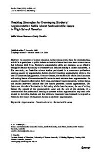
* Conjunctive resource allocation:A part requires ni units of each resource type from a set of resource types for its next processing step. · Conjunctive/disjunctive resource allocation: The request structure of a part can be any combination of ANDs and ORs. In each of these models, a single-unit allocation results when the number of units of each resource type requested always is 1. This work addresses the design of control policies for allocating buffer space to competing parts in an FMS. We assume the FMS to be composed of a set of machines that produce a set of part types. Further, we assume each machine to have a finite amount of buffer capacity and each part type to require a single unit of buffer capacity at each machine in its predefined sequence of machines (its route). This resource allocation scenario falls under the singleunit single-resource model, and the four necessary conditions for deadlock that follow (see Silberschatz and Peterson 1991) either are present or can arise easily. 1. Mutualexclusion: A unit of buffer capacity cannot be occupied simultaneously by several parts. 2. Holdand wait: A part maintains exclusive use of one unit of buffer capacity while waiting for the next required unit to be allocated. 3. No pre-emption: Parts cannot force other parts to give up their buffer capacity. 4. Circularwait: States exist in which there is a sequence of n parts such that the ith requires the buffer capacity of the (i + 1)th and the nth requires the buffer capacity of the first. Furthermore, for single-unit single-resource buffer allocation, deadlock is defined as follows. Definition 1: An FMS is deadlocked if a set of parts exists in the system such that each part in the set has requested and is awaiting the buffer capacity occupied by another part in the set. In general, the RAS state can be concisely described using a system resource allocation graph, as shown in figure 1. This is a bipartite graph with one set of nodes representing the resources and the other representing the processes. A directed edge connects process to resource (request edge) if that process is requesting a unit of that resource. A directed edge connects resource to process (assignment edge) if aunit of that resource is granted to that process. Note that dots in the resource nodes indicate the number of instances of the resource. A cycle in this graph (circular wait) is a necessary but not a sufficient condition for system deadlock. For example, figure la shows a system state in which a cycle but no deadlock exists. The system in figure lb is in deadlock. Methods for dealing with deadlock either preclude the possibility of deadlock by preventing some necessary condition (such as a cycle in the resource allocation graph) or detect and resolve a deadlock when it occurs. In general, these methods are categorized as follows:
9
DESIGN GUIDELINES FOR DEADLOCK HANDLING
R2
(a)
R2
(b)
Figure 1. System resource allocation graph.
* Deadlock prevention methods prespecify how processes can request resources so that the four necessary conditions are never satisfied simultaneously. * Deadlock avoidance uses current state information along with some additional information on how processes request resources to control resource allocation so that the four necessary conditions are never satisfied simultaneously. · Deadlock detection and resolution allows deadlock to occur, then employs algorithms for detecting and correcting them. Deadlock prevention in manufacturing places extensive restrictions on system operation so that deadlock is not possible. A typical prevention policy would group part types so that the FMS could run each group as a flow line. In this way, circular wait, and therefore deadlock, never occurs, although system flexibility is greatly reduced. Because of this flexibility cost, manufacturing researchers have tended to focus on detection/resolution and avoidance strategies. Almost all manufacturing-related deadlock literature deals with buffer allocation under the single-unit, single-resource classification of the taxonomy. In a series of papers, Wysk, Yang, and Joshi (1991, 1994), Kumaran, Chang, Cho, and Wysk (1994), and Cho, Kumaran, and Wysk (1995), discuss detection and recovery approaches based on system status graphs similar in nature to the allocation graph presented earlier. Cycles in the graph are identified and then analyzed for a deadlock sufficiency condition. If a deadlock is indicated, reserved buffer space is judiciously applied to eliminate the deadlock. In general, this work suffers from the complexity involved in cycle enumeration (see Mateti and Deo 1976). Required computation becomes intractable as the system size increases and so the approach is not scalable. Leung and Sheen (1993) discuss a detection and recovery approach that maintains a single unit of free buffer capacity in a central storage area. The detection algorithm checks to see if all machines are blocked simultaneously. If so, careful swapping between the deadlocked machines and the free buffer space is implemented until the deadlock is resolved. Although detection/recovery is adequate for computer systems where deadlocked processes simply can be "killed," this approach has several disadvantages in manufacturing where deadlocked processes are tangible entities that must be physically manipulated (and that represent wealth). First, decisions regarding the set of deadlocked parts to move during recovery must be automated. Furthermore, all parts removed from the system (or placed
10
MARK LAWLEY, SPIRIDON REVELIOTIS, AND PLACID FERREIRA
in idle buffers) during recovery must be tracked and reintroduced as quickly as possible, lest orders go unfilled. Also, resolution must be expedient, otherwise the system spends a good deal of time in an unprofitable state. Finally, once deadlock is resolved, there is no guarantee that it will not quickly reoccur. Because of these problems, deadlock avoidance is the preferable deadlock handling strategy for allocating buffer capacity. Deadlock avoidance strategies use current state information when deciding whether to grant pending resource requests. Several researchers have investigated avoidance methods. Viswanadham, Narahari, and Johnson (1990) develop a deadlock avoidance method based on Petri net models of the system. Finite-step look ahead of the Petri net reachability tree is used to search for and avoid deadlock states. Although the procedure reduces the probability of deadlock, it does not guarantee deadlock-free operation. The approaches discussed in Wysk et al. (1991, 1994), Kumaran et al. (1994), and Cho et al. (1995), are extended to avoidance but problems with cycle enumeration remain. Cho et al. (1995) assert that potential next states must be checked for both deadlock and impending deadlock (although deadlock is not present, it cannot be avoided). They then develop approaches for detecting impending deadlocks. As will be discussed later, however, the problem of detecting an impending deadlock (which we refer to as a deadlock-free unsafe state) is NP-complete for this resource allocation class. As before, these approaches do not scale. Leung and Sheen (1993) develop a hardware-based deadlock avoidance strategy that uses free buffer space in a central buffer to resolve a deadlock when it occurs. The approach depends on a physical swapping mechanism that is expensive in both time and resources when applied to manufacturing systems. Banaszak and Krogh (1990) develop a policy that models the production sequence of each part type as a Petri net. To fire, enabled transitions must satisfy a deadlock avoidance algorithm (DAA). DAA requirements are established by partitioning each production sequence into a set of zones, each composed of shared and unshared subzones. The DAA constrains the number of parts in a zone to be no greater than the capacity of the unshared subzone. Furthermore, a part can proceed in a shared subzone only if capacity is available on all remaining resources in the shared subzone. The authors also introduce the important concept of a restricted deadlock, a situation in which a deadlock avoidance policy admits states from which the empty state is unreachable due to policy imposed restrictions. This will be discussed in detail later. Hsieh and Chang (1994) model the FMS as a controlled-production Petri net and generate a distinguished marking, X, that encodes the minimal resource requirements for parts in the system. An enabled control action is allowed if a constrained search reaches a marking that "covers" *. Scheduling heuristics are used to constrain the search. Finally, our research, beginning with Gaarder (1993), extended in Lawley (1995) and Reveliotis (1995), and reported in Lawley and Ferreira (1994), Lawley, Reveliotis, and Ferreira (1996), Reveliotis and Ferreira (1996a, 1996b), and Lawley, Reveliotis, and Ferreira (1997), uses the finite state automaton as a computational model of the FMS state space. The topology of the state transition diagram provides the theoretical setting for study of the deadlock phenomena. Avoidance strategies (SCPs) are characterized as cuts that guarantee certain structural characteristics of the subdigraph containing the empty state (this will be discussed in detail later). Two families of SCPs, expressible as sets of linear integer inequalities, are developed. States satisfying the inequalities are admitted (the FMS is allowed to
11
DESIGN GUIDELINES FOR DEADLOCK HANDLING
visit these states), whereas states violating the inequalities are rejected (the FMS is not allowed to visit these states). Furthermore, a generic policy development procedure emerged that should prove useful to other researchers interested in developing deadlock avoidance strategies. This procedure is based on four requirements that any such policy must satisfy to be useful. In the next section, we discuss these requirements in depth and show each to be essential for a viable control policy. In section 4, we develop guidelines for researchers interested in developing new policies and justify the search for new policies. Section 5 presents an example policy development using these guidelines. 3. Requirements for structural control policies The objective of an SCP is to guarantee deadlock-free FMS operation in real time while supporting FMS configuration flexibility. This section precisely defines the implications of this statement in terms of the issues of policy correctness, scalability, configurability, and efficiency.
3.1. Introduction We begin by introducing sufficient formalism to model relevant FMS features. Let M = {M 1, M2,.... MIMI} represent the set of machines in the system, and C(Mi) be a function that returns the buffer capacity of machine i. Furthermore, let P = {P1, P2, ... , P1I 1} be the set of part types produced by the FMS where each Pk E P is represented as an ordered set of stages, Pk = (Pkl, Pk2 . . . PklPkl) Pkm represents the mth stage of part type k, and the symbol r denotes parts in the system (Tkm represents a currently executing part of type k in its mth processing stage). Let R = {R 1, R2, . ., Rp} be the set of routes, where Rk = (Mfk(l), Mfk(2) . . . Mfk(iPkl)) is the route for Pk. Note that fk(j) returns the jth machine of Rk for j = 1... Pk, and there is a natural mapping between Pk and Rk; namely, g(Pkm) = Mfk(m). Clearly, g partitions the set of all stages into IMI equivalence classes, based on the machine used. Let S(Mi) = {Pkm I g(Pkm) = Mi V k = 1 ... IPI, m = 1 ... IPk|}, that is, the set of all stages processed by Mi, and F(Mi) = {PklPkl I g(PklPkl) = Mi V k = 1... IPI}, that is, the set of terminal stages operated on by Mi. See table 1 for a notation summary. Definition 2: The state, S, of an FMS under the single-unit single-resource buffer allocation model is a nonnegative integer vector of the form
S = (Ir7lld, il2l ...t. ITPllIP; 1 r211,17221, 17Ilpl21... . .lpllplPll)T
7T2IP 21I . . ; ITipII I,
where Epk& E(M,) IrTkmI < C(M) V Mi E M and IrTkmI indicates the number of type k parts in the mth stage of processing that currently occupy buffer capacity in the FMS. The dimension of S is I kL IPk, the cumulative route length, CRL.
12
MARK LAWLEY, SPIRIDON REVELIOTIS, AND PLACID FERREIRA
Table 1. Notation M C(M,) P Pk Pkm 7rkm RkU
5(Mi) r(M,)
RUi LU, S SE
G = (VE) V E Vsafe Vunsafe VDL
VR VUR Gadmit =
(Vadmit, Eadmit)
Vadit Eadmil
RC(S,) Vsample Vsadmit Vsreject
G* = (V*, E*) V*
E* C(i;j) 0
Set of FMS machines Buffer capacity of machine i Set of part types produced by the FMS Part type k The mth stage of part type k Part of type k in its mth stage of processing Route of part type k The jth machine of the route of part type k Set of part stages processed by machine i Set of terminal part stages process by machine i Set of "right" and "undirected" part stages processed by machine i Set of "left" and "undirected" part stages processed by machine i FMS state vector Empty state State space digraph Set of all FMS states Set of all FMS state transitions Set of all states from which the FMS can be emptied using transitions in set E Set of all states from which the FMS cannot be emptied using transitions in set E Set of all FMS deadlock states Set of all states reachable from the empty state using transitions in set E Set of all states unreachable from the empty state using transistions in set E Subdigraph induced by an SCP Set of all states accepted by an SCP' Set of all state transitions between states admitted by an SCP Set of all states reachable from state S, using the transitions in Eadmit Amount of occupied buffer capacity in state Si Sample of FMS states Subset of sampled states admitted by an SCP Subset of sampled states rejected by an SCP Cospace of G Set of all FMS states, same as V Set all transitions of set E, each reversed in sense Number of ways of selecting j objects from i total objects "Big O" notation indicates approximate number of steps to perform a computation
The state vector, S, describes the current allocation of buffer space along with the current stage of processing for all parts residing in the FMS. It implicitly provides information regarding future requirements since routes are known. Note that the FMS changes state in one of three ways: (1) a new part is loaded into the system, (2) some part already in the system is advanced one step in its route, or (3) a finished part leaves the system. We assume that a single-state transition corresponds to the single-step advancement of a single part and that transitions are instantaneous. Finally, note that the "size" of FMS configuration is characterized by MI, the number of machines; IPI, the number of part types; and CRL, the cumulative route length. The FMS state space is the set of all such states augmented with state transition information. Such a space is represented conveniently by a directed graph, G = (V E), where vertices represent states and directed edges represent state transition. Directed edge (Si, Sj)
DESIGN GUIDELINES FOR DEADLOCK HANDLING
13
is present if and only if the single-step advancement of one part in Si results in Sj. In general, V can be partitioned based on state safeness, where a state is safe if and only if a sequence of state transitions exists that leads to the empty state, SE. State safety is defined inductively as follows. Definition 3: 1- SE E Vsafe 2. Sj E Vsafe A (Si, Sj)C E 3. Si Vsafe - Si E Vunsafe
Si E Vsafe
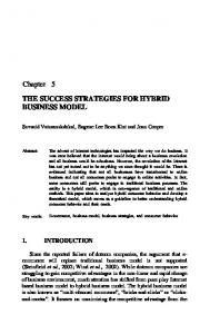
Let VDL represent the set of deadlocked states, and note that VDL C Vunsafe. It generally is not true that VDL = Vunsafe . For example, figure 2 demonstrates a deadlock-free unsafe state for a small system. Although the state in the top of figure 2 is deadlock free, both successor states exhibit deadlock. The implications of this will be discussed shortly. The term Si G Vsafe implies that SE is reachable from Si, not the converse. A state that is not reachable from SE, although it might be safe, will never be encountered under normal FMS operation. State reachabilityfromSE is defined inductively as follows. Definition 4: 1. SE E VR 2. Sj E VR A(Sj, Si) EE 3. Si T VR - Si E VUR
Si E VR
R 1= (M 1,M 2 ,M
3
) R 2 = (M 3 ,M 2 ,M 1)
Deadlock-free unsafe state
Successor deadlock states
Figure2. Deadlock-free unsafe state and successor deadlock states.
14
MARK LAWLEY, SPIRIDON REVELIOTIS, AND PLACID FERREIRA
Note that if state Sj is encountered under normal FMS operation, then Sj E VR. We now formally define strong connectedness with SE as follows. Definition 5: Si and SE are strongly connected in G if and only if Si E Vsafe n VR. These set relationships are summarized in figure 3. With these definitions, we are in a position to discuss the requirements that a viable SCP must fulfill. We begin with correctness. 3.2. SCP correctness An SCP that guarantees the existence of a sequence of state transitions leading to the empty state is referred to as correct. Let Vadmit be the set of states admitted by an SCP under normal FMS operation (Vadmit C VR). Then, there are three elements to policy correctness. First, note that SE E Vadmit, or else the SCP will not allow the system to be emptied. Second, if Vadmit n Vunsafe 0, then the policy admits some unsafe state and cannot be correct. Clearly, Vadmit n Vunsafe = 0 is a basic requirement for SCP correctness. Finally, assume Vadmit n Vunsafe = 0; that is, all states admitted by the SCP are safe. Consider the subdigraph induced by Vadmit, Gadmit = (Vadmit, Eadmit), where Eadmit = {Si, Sj) I Si, Sj E
Vadmit A (Si, Sj) E E}. Suppose there exists Su E Vadmit such that {S, I (Sn, Sv) E Eadmit} 0. Then, in the induced subdigraph, Gadmit, the safe state, Su, has no successor and is a deadlock. In figure 4, for example, no successor of admissible state SA is admitted. When the FMS visits state SA, policy constraints prevent all state transition, and the SCP must be violated to proceed. Once outside the protection of the policy, however, the system can easily cross the safe/unsafe partition and proceed to deadlock. This is the restricted or induced deadlock situation, where an SCP admits states from which the system cannot be emptied due to its own restriction. A more concrete example is the "naive" policy. This policy allows only those states that satisfy the following constraints: E Irkm < Pkam E(Mi)
Cc( Mi)
VMi E M
In words, this SCP rejects any state containing a full machine (note that it applies only to those systems with C(Mi) > 1 V Mi E M). Clearly, deadlock as given in Definition 1 will
Figure3. FMS state space.
DESIGN GUIDELINES FOR DEADLOCK HANDLING
15
Figure4. Policy induced deadlock.
Ri=(M 1 ,M 2 ) R 2 =(M 2 ,M 1) M,
M2
Figure5. Induced deadlock in the native SCP.
never occur. However, the policy induces deadlock, as demonstrated in figure 5. This small system has reached an admissible state that has no admissible successor state. If either part moves forward in its route, the SCP is violated. More generally, for every Si C Vadnmit, let RC(Si) = {Sj I Sj reachable from Si in Gadmit}.
An SCP induces deadlock if and only if Sk E Vadreit exists such that Vadmit \ RC(Sk) 0; that is, Gadit is not strongly connected. Note that this requirement implies Vadmit Vunsafe = 0. We, therefore, have the following definition.
n
Definition 6: An SCP is correct if and only if, under normal FMS operation (Vadmit C VR), its induced subdigraph, Gadmit = (Vadmit, Eadmit), satisfies the following conditions: 1. SE E Vadmit
2. V Si E Vadmit, Vadmit \ RC(Si) = 0
3.3. SCP scalability Consider an SCP for which Vadnit = Vsafe n VR. We refer to such a policy as optimal since
it allows every reachable safe state and rejects every unsafe state. In general, the optimal policy cannot be implemented as a real-time control policy, since the state safety problem is NP-complete for this RAS class (see Araki, Sugiyama, Kasami, and Okui 1977). This is a direct result of the existence of deadlock-free unsafe states; that is, VDL 0 Vunsafe, for
16
MARK LAWLEY, SPIRIDON REVELIOTIS, AND PLACID FERREIRA
Machines
4
Pat Types
4
Routes
(412)
Total States
183,367,800
Capacities (4 52 6)
(4131)
(312341)
(124234)
Figure 6. Example FMS state space size.
this RAS class (if VDL = Vunsafe were true, deadlock avoidance would be possible via detection in the next state, a tractable approach since deadlock detection can be carried out in polynomial time and space). Indeed, optimality can be computationally prohibitive for even small systems. To see this, we briefly investigate the number of states in the FMS state space. First note that Mi can be thought of as a collection of C(Mi) identical boxes, each of unit capacity. The stages in 5(Mi) can be modeled as ((Mi)I + 1) unlimited collections of objects, distinct between but identical within collections (we add 1 to denote the empty object). We now recall that the number of selections with repetition of r objects chosen from n types is C(r + n - 1; r). Therefore, the number of states in the FMS state space is FI= C[C(Mi) + 15(Mi)l; C(Mi)], where the ith term is the number of states exhibited by Mi. This product of binomial coefficients is no smaller than 21MI and typically much larger than IMIMI l, clearly exponential in the size of FMS configuration. For example, the small system of figure 6 exhibits 1.83 x 10⁸ states. In general, real-time control policies cannot perform explicit analysis or unconstrained search of the FMS state space for even small systems. For real-time policies, we require the amount of computation to be bounded by a polynomial function of FMS configuration size. For example, suppose SCPI executes in IMI3 steps (recall that IMI is the number of machines), while SCP 2 requires 21MI steps. If we have five machines, then neither policy is prohibitive. Clearly, however, the computational requirements of SCP2 grow much faster than those of SCP 1. If our system grows to, say, 50 machines, SCP 1 is still feasible, that is, it is scalable, whereas SCP 2 must be scrapped. We formally define SCP scalability as follows. Definition 7: An SCP is scalable if the time and space required for execution is bounded by a polynomial function of FMS configuration size.
3.4. SCP configurability As discussed in the introduction, configuration flexibility is an increasingly important characteristic for automated manufacturing systems. An SCP is configurable if the operating constraints that it imposes can be generated quickly for new FMS configurations. This implies that SCP correctness and scalability must be independent of FMS configuration; that is, configuration-specific deadlock analysis must not be required for a configurable SCP. Therefore, if new machines and part types are added to an existing system, the new deadlock-free operating constraints must be generated without analyzing the deadlock characteristics of the new configuration. We define configurability as follows.
DESIGN GUIDELINES FOR DEADLOCK HANDLING
17
Definition 8: An SCP is configurable if the time and space required for constraint generation is bounded by an polynomial function of FMS configuration size. 3.5. SCP efficiency In general, polynomial execution implies suboptimality, Vadmit C (Vsafe n VR) ( Vadmit; that is, a scalable SCP, in general, will reject many safe and reachable states. If too many of these states are rejected, however, the SCP will restrict flexibility and will not be usable. For example, a policy that allows only one part in the system at a time is correct, scalable, and configurable, although clearly too inefficient to be given serious consideration. An SCP should be as permissive as possible, allowing dispatching and order release policies the greatest possible leeway. The efficiency measure developed in this work is defined as follows. Definition 9: The efficiency of an SCP for a particular FMS configuration is the ratio IVadmitl/lVsafel-
4. Guidelines for developing structural control policies In section 3, we have developed the four key requirements that an SCP must fulfill if it is to be a usable solution to the deadlock avoidance problem. This section develops guidelines for designing policies satisfying these requirements. 4.1. Deadlock avoidance perspective SCP development is a creative process that begins with a unique perspective of how deadlock can be avoided. For example, Banaszak and Krogh (1990) use the perspective that some FMS machines are shared by many part types while others are used exclusively by single part types. When combined with concepts from the Banker's algorithm (see Silberschatz and Peterson 1991), this perspective leads to a viable policy. Hsieh and Chang (1994) use the perspective that deadlock can be avoided if a reachable state has sufficient available resources to cover the resource needs of all parts in the current state. Again, this perspective leads to a viable policy. Clearly, the first step in policy design is to develop a new perspective on how to avoid deadlock. Because there is no easy way to develop deadlock avoidance perspectives (since this depends on ingenuity and background), we believe that any new perspective leading to a correct, scalable, and configurable policy is a significant research contribution. In the following subsections, we discuss how to determine whether a perspective can be used to avoid deadlock. 4.2. Policy correctness Once a unique perspective as been established, deadlock must be characterized with respect to that viewpoint. There are two types of deadlock characterization. The first involves
18
MARK LAWLEY, SPIRIDON REVELIOTIS, AND PLACID FERREIRA
identifying necessary and sufficient conditions for deadlock. For example, if condition A is necessary and sufficient for deadlock occurrence, then A both implies and is implied by deadlock. If VA is the set of states exhibiting condition A, then VA = VDL. An SCP with Vadmit = V\VA clearly will reject VDL. However, since VA = VDL • Vunsafe (as was shown earlier), such an SCP, in general, will not be correct. Therefore, SCPs must use weaker necessary (and insufficient) conditions. For example, if B is necessary but insufficient for deadlock, then B exists when deadlock exists, but the converse is not true; that is, VDL C VB. An SCP with Vadmit = V \ VB will clearly reject VDL. Furthermore, if Vunsafe C VB, then the SCP will also reject Vu,safe. Therefore, our first step in defining a correct policy (with respect to our unique perspective) is to identify a necessary but insufficient condition, B, for deadlock and prove that VDL C VB ¢ VDL. This proof must be general, that is, it must not use configuration-specific information, otherwise the SCP will not be configurable. After we have proven the candidate condition, B, to be necessary but not sufficient for deadlock, we must develop an SCP that rejects a state, Si, if and only if Si E VB. Therefore, Vadmit = V\ VB. We must show that the induced subdigraph, Gadmit = (Vadmit, Eadmit), satisfies both conditions of Definition 6; that is, (1) SE E Vadmit and (2) V Si E Vadmit,
Vadmit \ RC(Si) - 0. Showing (1) is trivial. To show (2), we can proceed by direct proof or by attempting to construct an induced deadlock state. Note that, if some portion of the FMS is in induced deadlock, then, by allowing no new parts to enter, the remainder of the system can be either emptied or brought to induced deadlock as well. Let Cp(Si) return the amount of occupied buffer capacity in state Si. Then, if (Si, Sj) E Eadmit and Cp(Si) = Cp(Sj), Sj follows Si only as the result of the movement of a part already in the system. In this proof, we assume that some portion of the system is in induced deadlock, the remainder of the system has been emptied, and no new parts are allowed to enter. We then attempt to construct a state, Si, that satisfies the SCP, Si E Vadmit, but that has no successor state (under these assumptions) that does the same; that is, we attempt to show that the set {Sj I Cp(Si) = Cp(Sj) A (Si, Sj) E Eadmit} is empty. If a contradiction arises, we conclude that Si does not exist and the policy is correct. If the construction is successful, we conclude the policy to be incorrect. As before, this proof must not use configuration-specific information, otherwise the SCP will not be configurable. To summarize, we seek conditions that (1) are present in every deadlock state, (2) are present in every unsafe state, and (3) guarantee that, for any state not exhibiting the condition, there exists a sequence of states not exhibiting the condition that leads to the empty state. Although it is generally straightforward to prove that a condition satisfies (1), the proof for (2) and (3) typically is more involved. A formal framework that can be used for correctness analysis has been developed and is presented in Reveliotis and Ferreira (1996b). 4.3. Configurabilityand scalability Algorithms that set up the SCP must be developed. These algorithms should accept the FMS configuration as input and generate the required operating constraints. Note that we must show these algorithms to be polynomial with respect to FMS configuration size. Furthermore, we must show the resultant operating constraints to be polynomial with respect to FMS configuration size.
DESIGN GUIDELINES FOR DEADLOCK HANDLING
19
4.4. SCP efficiency Recall from Definition 9 that SCP efficiency is defined as Vadmntl/IVsafel. Note that the computation of either of these is an intractable problem. Therefore, a sampling approach must be developed. Suppose we wish to investigate the efficiency of SCP1 with respect to a particular FMS configuration and that we have collected a sample of states, Vsample C Vsafe. Then SCP 1 partitions Vsample as follows: Vsample = Vsadmit U Vsreject, where Vsadmit Vsreject = 0. Note that Vsadmit is the subset of sample states allowed by SCP1 and Vsreject is the subset of sample states rejected by SCP1. Clearly, Vsadmit C Vadmit and Vsreject C V \ Vadmit. A point
estimate of the efficiency of SCPI, therefore, is IVsadmitl\lVsamplel. Note, however, that deciding whether a given state belongs to Vsafe in general is NP-complete. We, therefore, require a state generation method that produces only safe states so that this intractable problem need not be addressed. The following definition is required. Definition 10: Let G = (V, E) be the state space digraph for a given FMS. Then the cospace is defined as G* = (V*, E*) where V* = V and E* = {(Sj, Si) (Si, Sj) E E}.
In words, the cospace, G*, reverses the sense of directed edges in G. The following theorem provides the basis for a safe state sampling procedure. Theorem 1: 1. VR = Vsafe 2. VUR = Vunsafe 3 Vaf, = VR 4
Vunsafe =
VUR
Proof. We prove 1 and leave 2-4 as an exercise for the reader. Suppose Si E VR. Then, there exists a sequence of edges in E* leading from SE to Si. Clearly, this sequence of edges (in reverse order and sense) represents a path from Si to SE in G; that is, Si E Vsafe. Therefore, V C Vsaf,. Now, suppose Si E Vafe. Then, there exists a sequence of edges in E leading from Si to SE. As before, this sequence of edges (in reverse order and sense) represents a path from SE to Si in G*; that is, Si E V. Therefore, V = Vsaf,. Note that 2-4 can be proven by similar reasoning. So, to generate a safe sample, Vsmpl, from G, we need only traverse the edges of G* and save every state encountered. This is easy to do, since following the edges of G* is equivalent to reversing the routes of the given FMS configuration and running it backward. Note that since some states might be encountered and saved several times, the resulting sample must be sorted and redundant states removed. Furthermore, note that, in general, Vsample VUR $A 0; that is, although Vsampe C Vafe, there is no guarantee that Vsample C Vsafe n VR. Indeed, we must take some precaution in our simulation, since we easily can encounter a state Si E VL C Vnafe that causes the simulation to halt. Finally, note that our traversal of G* should be as random as possible.
20
MARK LAWLEY, SPIRIDON REVELIOTIS, AND PLACID FERREIRA
4.5. Guidelines The following sequence of steps provides guidelines for developing SCPs: 1. Identify a necessary condition for-deadlock with respect to some unique perspective of the FMS. 2. Given this necessary condition, define a policy by the following rule. An enabled state transition is admissible if and only if the resulting state does not exhibit the necessary condition. 3. Develop algorithms for policy setup and show them to be polynomial in FMS configuration size. 4. Show policy execution to be polynomial in FMS configuration size. 5. Prove that the policy does not induce deadlock. 6. Perform policy efficiency studies through state space sampling. Note that the induced deadlock proof is deferred until step 5, since it is most difficult and need not be undertaken if steps 3 and 4 are not successful. Finally, we justify the importance of searching for new policies by noting that the disjunction of two or more correct policies is itself a correct policy; that is, SCPI V SCP 2 is correct if SCPI and SCP 2 are correct. Assume that SCPI and SCP2 are to be applied to a particular FMS configuration, and that VI and V2 are the state sets admitted by SCPI and SCP 2, respectively. Clearly, the set of states admitted by $CPI V SCP2 is Vl U V2. SCP 1 V SCP 2 provides better efficiency if (V1 ¢ V2) A (V2 4 V); that is, the admissible space of one policy is not a subset of the admissible space of the other. Note that V1 n V2 $ 0, since the empty state, SE, belongs to both. We now provide an example of SCP development using the preceding set of guidelines.
5. Counterflow systems and the order policy To demonstrate the guidelines discussed in the previous section, we develop an SCP for single-unit, single-resource buffer space allocation in counterflow systems (referred to simply as counterflow). We use the counterflow system for illustrative purposes because avoiding deadlock is nontrivial and yet the correctness proofs are relatively straightforward due to routing restrictions. For this analysis, we define a counterflow system as follows. Definition 11: A counterflow system is a special chse of the FMS with the following features: 1. P = {PR, PL}
2. IPRI = PLI IMI 3. 3f: {1, 2,...,PR} - {1, 2,...,IMI} (bijective) such that RR = (Mf(l), Mf(2), -. Mf (pRI)) and RL = reverse (RR) In words, there exist two part types, PR and PL, with routes passing through all machines (no cycles) and in opposite directions. In figure 7, for example, RR = (M 1, M2, M3 , M4)
21
DESIGN GUIDELINES FOR DEADLOCK HANDLING
and RL = (M4, M3 , M2 , Mi). Let us say that each rIR flows right and each rrL flows left. Counterflow systems have high potential for blocking and, therefore, prove useful in the study of deadlock. Our perspective for avoiding deadlock is that parts flowing through the same set of machines but in opposite directions, at some point, must be able to pass. Figure 8 demonstrates a deadlocked counterflow system. From this figure, we make the following observation: When a counterflow system is deadlocked, a machine is filled with instances of 7rR (M 1) and another is filled with instances of 7rL (M4 ) such that the first is to the left of the second. This condition is clearly not sufficient (it does not imply deadlock), as can be seen from figure 9 (empty the system by advancing one instance of 7rR to M2 and streaming the remaining instances of 7rL). If the condition can be proven to be necessary for deadlock, we can further investigate its use as a basis for an SCP. We state and prove the following theorem. Theorem 2: Let D be a set of deadlocked machines in a counterflow system. Then, there is a pair of machines in D, (Mi, Mk), such that Mi is filled with instances of irR, Mk is filled with instances of rTL,and Mi is to the left of Mk.
Proof. Let D be a set of deadlocked machines in a counterflow system, where a machine belongs to D if and only if it if filled with deadlocked parts. Let ML be the leftmost machine RR=(MI,M 2,M 3 ,M 4 ) Ml
RL=(M 4 ,M 3 ,M 2 ,M1)
M2
oO O 000000
M3
oo
Figure 7. Counterflow system. M2
I Figure 8. Deadlocked counterflow system. M1
M2
000 ©© QDOQ Figure9. Necessary but not sufficient for deadlock.
M3
22
MARK LAWLEY, SPIRIDON REVELIOTIS, AND PLACID FERREIRA
of D. If ML contains a WL, then TrL next requires a machine not in D. This implies that neither 7rL nor ML is deadlocked, and we have a contradiction. Therefore, ML must be filled with instances of irR. Similar reasoning shows MR filled with instances of irL, where MR is the rightmost machine of D. We can now proceed to formalize these concepts and develop an SCP that checks for this condition in the next state. Let the function h be a bijective mapping from the set of machines, M, to the set of integers {1, 2, ... , ]MI}, h: M - {1, 2 .. , IMI. For the counterflow system, h(Mf(i)) = i. Let RUi be the set of "right" stages in 5(Mi) and LUi be the set of "left" stages in ((Mi). Note that 5(Mi) \ F(Mi) = RUi U LUi (we ignore terminal stages). Then, the operating constraints are given as follows. Definition 12: E
PRERUi
17TRm +
)Y
PLMELUj
IrTLm < C(M) + C(Mj)
V Mi, Mj such that h(Mi) < h(Mj)
Note that a constraint is generated for each pair of machines. This constraint sums the current number of instances of iiR of the machine low in the order with the current number of instances of 7rL of the machine high in the order and ensures that this sum is always less than the combined capacity of the two machines. Applying this policy to the system in figure 7 yields the following: RUI = {TRI} RU 2 = {7rR2}
LU1 = 0 LU2 = {rL3}
RU 3 = {7TR3} RU 4 = 0
LU3 = {fTL2} LU4 = {IrLI}
ITRII + ITL3 < 3 + 4 = 7 ITRII + TL2 < 3 + 3 = 6 IrR11 + I,rLI < 3 + 2 = 5
4.
IITR2 + IL21 < 4 + 3 = 7
(M1 and M2 ) (M 1 and M3 ) (Ml and M4 )
5. 6.
ITR21 + LI I < 4 + 2 = 6 I7TR31 +I TLI < 3 + 2 = 5
(M 2 and M4) (M3 and M4 )
1.
2.
3.
(M2 and M3 )
Constraint 1, for example, assures that the number of instances of rR at Ml plus the number of instances of ITL at M 2 is always less than the combined capacities of M 1 and M2. These constraints will disallow states such as that of figure 9, which violates constraint 3. States such as that of figure 10, where machines filled with instances of ITL are to the left of machines filled those of IrR, are allowed. We now conjecture that this policy is both configurable (for counterflow as defined previously) and scalable; that is, it can be set up and executed in polynomial time. In general, the policy is not configurable, since it assumes certain restrictions on part types and routes. The approach is to show policy viability for counterflow and then extend it to systems with no restrictions.
23
DESIGN GUIDELINES FOR DEADLOCK HANDLING
M2
1R0 Figure10. Admissible state.
Theorem 3: The policy is configurable and scalable for counterflow systems. Proof The steps involved in setting up the policy for a counterflow system are as follows: 1. Order the machines with respect to the route, RR. 2. Partition ((Mi) \ F(Mi) into RUi and LUi for each Mi E M. 3. Generate a constraint for each pair of machines. Step 1 requires the computation of h(Mf(i)) for i = 1... IMI, which takes O(IMI) steps. For the second step, at most CRL stages must be categorized as "right" or "left." An upper bound is O(CRL). For the third step, the number of constraints will be C(IM; 2), that is, IMI machines taken two at a time, and each constraint will have no more than CRL terms. Therefore, an upper bound is O(CRL* MI2). Since constraint execution requires evaluation of IMI2 linear inequalities, each with no more than CRL terms, an upper bound on execution is O(CRL*1M12). At this point, for the restricted case of counterflow, we have established a unique perspective, identified and proven a necessary deadlock condition, developed an SCP that rejects any state exhibiting condition, and shown the SCP to be configurable and scalable. The next step is to determine whether the policy induces deadlock. Theorem 4: The order policy does not induce deadlock in counter-flow systems. Proof Assume that the policy induces deadlock, the FMS has been emptied of all parts not in induced deadlock, and no new part is allowed to enter the system. Then, there exists a state, Sk E Vadmit, such that {Sn Cp(Sk) = Cp(Sn) A (Sk, Sn) CEadmit} = 0; that is, Sk has no admissible successor. Note that Sk £ Vadmit implies that the constraints ' PRERUi
1irLm < c(M) + C(Mj)
E
I7TRm +
V Mi, Mj such that
h(Mi)
PLgLUj
are satisfied, and {S, I Cp(Sk) = Cp(Sn) / (Sk, Sn) moves forward in its route, we have
< h(Mj)
Eadmit} = 0 implies that, if any part
3Mi, Mj such that h(Mi) < h(Mj) with
E PRmERUi
IT7Rml +
E
I7TLm = C(M) + C(M)
PLmELUi
Then Sk must have at least one machine, say M, such that either EPLmELU. I7rLm = C(Mu) or YPRmERUu ITRm = C(Mu) since after the movement of one part, there will be two
24
MARK LAWLEY, SPIRIDON REVELIOTIS, AND PLACID FERREIRA
machines, one filled with instances of TR and one filled with instances of rL. Because the movement of one part cannot cause both, one already must exist. Without loss of generality, assume that MU is the machine of highest order, such that 1 PRERuu I*rTRmI = C(Mu); that is, it is the rightmost machine filled with instances of rTR. No machine of an order higher than Mu can be filled with rrL, otherwise the policy is violated. Also, all of the *R at Mu are blocked, otherwise a ITR of Mu could move to a machine of a higher order, and the resulting state would not violate the policy. Therefore, all rR of Mu are awaiting buffer capacity at a machine of a higher order that is filled to capacity, not with TR (by assumption), not with TL (since the policy is not violated), but with some combination of TR and iL. Let MW be this machine. Note that the *TR of M, are awaiting buffer capacity at a machine of a higher order and are blocked, else one could move forward with the resulting state not violating the policy. Now suppose Mz to be the machine of the highest order for which some *TR is waiting. Mz must be filled to capacity, not with TR (by assumption), not with rL (since the policy is not violated), but with some combination of TrR and TL. Furthermore, no rR on Mz is waiting for buffer capacity on a machine of a higher order (by assumption). These parts must be ready to leave the system and can do so without violating policy constraints (a contradiction). Therefore, the assumption that an induced deadlock state exists is incorrect, and we conclude that the policy is correct. A provably correct and scalable SCP has now been constructed for single-unit, singleresource buffer allocation in counterflow FMSs. For completeness, we extend the policy to systems without routing restrictions, but forego the proofs as being beyond the scope of the paper. For details, see Lawley (1995). Definition 13: Let (Mfk(m),Mfk(m+l ) ... Mfk(lpk)) be the remaining route of state Pkm. If the sequence (h(Mfk(m)), h(Mfk(m+l)),... h(Mfk(lpkI))) (where h totally orders M) is monotone increasing, then the stage Pkm is a "right" stage. If (h(Mfk(m)), h(Mfk(m+ )) ... h(Mfk(lpkl))) is monotone decreasing, then the stage Pkm is a "left" stage. Otherwise, Pkm is "undirected." If m = Pk, then the stage is terminal and ignored. Theorem 5: A correct, configurable, and scalable SCP with no route restrictions is given by , Pk,,ERU
I km +
A,
ITkml < C(Mi) + C(Mj)
Pk,,ELUj
V Mi, Mj such that h(Mi)