The multidisciplinary miniature robotics team at. Michigan State University is ... ROSTAM [5], NINJA-1 [10]), and ROBUG II [11] are all quadruped robots featuring ...
Design, Implementation, and Evaluation of an Under-Actuated Miniature Biped Climbing Robot Mark Minor1, Hans Dulimarta2, Girish Danghi3 Ranjan Mukherjee1, R.Lal Tummala3, Dean Aslam3 Mechanical1 and Electrical3 Engineering Depts. Michigan State University East Lansing, MI 48824 USA
Department of Informatics2 Institute of Technology Bandung Bandung 40132, INDONESIA
Abstract
ankles at the ends of the legs support Smart Robotic Feet (SRF) [2]. Steering is provided by one of these ankles. An under actuated structure allows three motors to drive the robot and permits weight reduction, space savings, and power conservation. To expedite the prototype process, RAMR1 has been built twice as large as its final version. This prototype measures approximately 45mm x 45mm x 248mm and weighs 335grams. The purpose of this paper is to communicate the design, implementation, and evaluation of this unique miniature robot. Section 2 reviews climbing robots in the literature relative to RAMR1. Section 3 discusses design constraints and in Section 4 a kinematics structure is selected. Design of the kinematics and structure are presented in Section 5 and the SRF is examined in Section 6. Section 7 discusses control of the under-actuated robot and Section 8 evaluates performance of the robot while climbing on, and between, planes of various inclinations. A review of future research and concluding remarks are in Section 9.
The design, implementation, and evaluation of a miniature biped robot for urban reconnaissance are presented. Design specifications for mobility, space requirement, weight, sensing, and control are defined. A revolute hip joint is selected based on its enhanced mobility and capability to function in reasonably confined spaces. Small size dictates minimal weight, which is achieved by an under actuated joint structure, providing steering at only one foot, minimizing sensors, and structural optimization. The Smart Robotic Foot supports the robot on a variety of smooth surfaces and provides feedback when a firm grip is established. Adaptable control strategies and dithering are implemented in lieu of minimal sensors and uncertainty created by backlash, gravity, and compliance in the suction feet. The robot is evaluated while performing tasks on surfaces with a variety of inclinations.
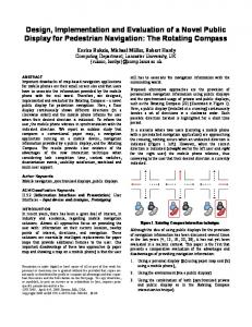
1. Introduction The multidisciplinary miniature robotics team at Michigan State University is developing miniature climbing robots for reconnaissance in urban environments [1]. These robots must be sufficiently small to travel through confined spaces, such as ventilation ducts, and to avoid detection while traveling along the outside of a building. It is assumed that the robot will travel on smooth surfaces with varying inclinations, such as floors, walls, and ceilings, and walk between such surfaces. Thus, the robot must be capable of adapting and reconfiguring for various environmental conditions, be self-contained, and be capable of carrying wireless sensors, such as a camera or microphone and their transmitters. The purpose of deploying such a robot would be for inspection, isolating the source of a biological hazard, or for gathering information about a hostile situation within a building. In response to these requirements a biped Reconfigurable Adaptable Miniature Robot (RAMR1) has been designed, constructed, and evaluated, Figure 1. RAMR1 is a biped robot with four joints and five links. A revolute hip joint supports two legs and articulated
A038.pdf
Figure 1. The first Reconfigurable Adaptable Minature Robot (RAMR1).
1
sliding segments, with suckers that grip the surface, to create locomotion. Versions of these robots have been created by Bar-Cohen [14], Gradetsky [15], Bach et al. [16], White et al. [17], and Briones et al. [18]. The last robot, known as ROBICEN, is the only one featuring an articulated segment for traversing between horizontal and inclined planes. Driven wheels are used for propulsion by Nishi [19] with suction gripping and magnetism gripping by Hirose [20] and Fuji [21].
2. Climbing Robots in the Literature Numerous robots exist for climbing inclined surfaces. Motivations are typically inspection or maintenance in dangerous environments like the exterior of a tall building, airplane, or ship, or in nuclear facilities or pipelines. Legged structures with two to eight legs are predominant. More limbs typically provide redundant support and often increase load capacity and safety. These benefits are achieved at the cost of increased complexity, size, and weight. Thus, when compactness and efficiency are critical, as in RAMR1, a structure with minimal weight and complexity is best applied. For these reasons, the biped format is an excellent candidate. Most biped robots use similar ankle structures where articulation is provided to both feet and steering to at least one foot. Bipeds vary most appreciably in the style of their middle joints. Robots using a revolute middle joint, similar to RAMR1, include the robot by Nishi [3] and the robot ROBIN [4]. A prismatic middle joint is used by ROSTAM IV [5], and Yano [6] applies a rigid central body. The benefits of these middle joint structures will be reviewed further in section 4. Beyond similarity in joint format, RAMR1 possesses several characteristics and features not found in the aforementioned biped robots. First, RAMR1 is the smallest of the biped robots found in the literature. In its longest configuration, RAMR1 measures 45mm by 45mm and 200mm and weighs 335gr. The next larger biped is Yano’s robot which measures 380mm x 250mm x 170mm and weighs 8kg. ROSTAM IV is the closest in mass, at 4kg. A substantial feature contributing to the small size and weight of RAMR1 is its under-actuated design. This is accomplished by coupling the rotation of the hip joint and one ankle joint to allow three motors to drive four joints. Thus the mass of the robot is reduced by 45grams. Similar weight and power savings benefits have also been demonstrated by Hirose [7]. The small penalty paid for under actuation is increased complexity of motion planning [8] and joint level control [9]. Despite these issues, under actuation decreases the mass of the robot and thus increases its safety while climbing inclined surfaces. As alternatives for increased safety and load capacity, we typically see quadruped and higher legged robots. ROSTAM [5], NINJA-1 [10]), and ROBUG II [11] are all quadruped robots featuring multiple Degree-Of-Freedom (DOF) legs protruding from a central body and supporting suction feet. Control of these robots is more complicated and they have typically been much larger robots. With even greater complexity, ROBUG III [12] and MSIV [13] use eight legs to provide increased stability. The tradeoff again is increased size, complexity, and weight. Simpler alternatives to the more complicated legged robots have been examined. A predominant theme uses
A038.pdf
3. Design Requirements The purpose of RAMR1 is autonomous reconnaissance in urban environments. The robot will be deployed on the exterior and interior surfaces of buildings and structures. It will traverse horizontal and vertically inclined surfaces and climb between them in order to deliver a reconnaissance sensor, such as a camera, to a specified location. The robot must be sufficiently small to travel through confined spaces and to also avert visual detection on the exterior of a building. As an autonomous system, the robot will eventually carry its own power source, processor, sensors, and accompanying hardware. Thus, minimization of power usage and weight are critical to prolonged operation. This initial prototype uses a tether to expedite structural and controller developments. Given these allowances and the mission scope of RAMR1, the following design criteria have been established: 1.
2. 3.
4. 5.
6.
Mobility. The robot must be capable of (a) walking and climbing on horizontal and vertical surfaces, (b) climbing between such surfaces, and (c) navigating between specified locations. Size. The robot should occupy a space less than 20cm x 5cm x 5cm. Space Requirements. The space required to maneuver the robot should be minimized to improve performance in confined locations. Weight. The SRF provide limited gripping capacity and thus weight must be minimized for safety. Sensors. Minimal sensors for walking and reconnaissance are used. This includes video, pressure sensors for foot placement, and binary joint sensors for calibration. Control. Adaptive control strategies are required due to backlash, compliance, and minimal sensing.
4. Kinematics Selection Several candidate designs were considered prior to selecting the format of RAMR1. The general biped form was given primary consideration for its simplicity and savings in weight and space. Within the biped format several kinematic designs were considered. The primary
2
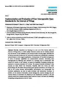
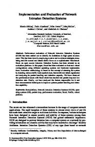
variation was the type of middle joint: revolute, prismatic, or a simple rigid body with no joint at all. Each format is predisposed to particular walking and climbing strides that directly influence the mobility of the robot and its space requirements. These characteristics have been quantified, normalized, and summed in weighted proportions to determine an optimum design for a particular environment [22, 23]. These methods and results are summarized to indicate the selection of the kinematic structure. To evaluate mobility, the capability of the three biped formats to move between inclined surfaces was evaluated. Planes with relative inclinations of -135°, -90°, -45°, 45°, 90°, and 135° were considered. Figure 2 shows the revolute hip biped climbing between several surfaces. Results indicate that the revolute structure performed best by crossing 100% of the inclinations, whereas the prismatic and simple joint structures were only capable of crossing 50% of the relative inclinations [22, 23]. Thus, the revolute hip joint improves the ability of the robot to reach around obstructions and place its foot. The joint structures were also evaluated to determine their maneuverability in limited spaces [22, 23]. This was accomplished by estimating the maximum cross sectional area swept by the robot during walking. Examples shown in Figure 3 illustrate space requirements for the revolute and prismatic hips, which performed best. The crawling strides of the prismatic and revolute hips required the least space of 17.5cm2 and 47.5 cm2, respectively. Thus, the best choice for unconfined operation is the revolute hip since it provides the best mobility and is capable of requiring minimal space. For confined operation the prismatic hip is best.
5. Kinematics and Structural Design The biped structure using the revolute hip joint has been selected for RAMR1. Illustrated diagrams of the robot can be seen in Figures 1 and 4. Minimization of weight, per design requirement 2, was given the highest priority during the design of the prototype. We first eliminated redundant actuators, which contribute significantly to net weight. Structural optimization was also applied to remove excess material from structural members. The result is an under-actuated five link biped robot with four joints and three actuators. Per the analysis of the previous section, a revolute hip joint has been used and is labeled Joint 2, Figure 4. The legs of the robot are formed by Links 2 and 3. Foot 1 (Link 1) uses a SRF for gripping the surface and the link is attached to Link 2 via Joint 1. The reconnaissance camera is also mounted at this foot to permit the robot to either look through a glass window or to use the camera like a periscope when Foot 2 supports the robot. Foot 2 (Link 5) also uses a SRF to grip the climbing surface. The foot is supported by the differential (Link 4). The differential provides the robot with steering capability. Foot 2 and the differential articulate relative to Link 3 via Joint 3. Redundant actuators have been eliminated by underactuation of the structure and by providing steering to only foot 2. Under actuation occurs through the coupling of Joints 2 and 3 via a timing belt. The timing belt and pulleys are clearly visible in Figure 4. The pulleys are sized such that the rotation at Joint 2 is twice that of Joint 3 and in the same direction. Further weight reductions are achieved by providing steering to only foot 2. The actuator for steering, Motor 1, is mounted on Link 3 to improve compactness of the design. Joints 2 and 3 are
Figure 2. Mobility examples of a revolute hip biped climbing between inclined planes.
A038.pdf
Figure 3. Crawling strides of the revolute and prismatic bipeds and space requirements.
3
Figure 4. The robot meets mobility requirements, but it is not well suited to extremely confined spaces.
actuated by Motor 2, which is integral to Link 2. Likewise, Motor 3 is integral to Link 2 and it actuates articulation of Joint 1. Reduced actuation has several side effects. Coupling of joints 2 and 3 predisposes the robot to walk in an endover-end flipping stride. This stride is excellent for mobility, but it is less desirable for operation in confined spaces. Also, the ability to maneuver the robot is limited by steering at only one foot. Motion planning must anticipate limited steering and coupled DOF, which has been addressed by Yue, et al. [8]. Likewise, uniform placement of foot 2 during walking and climbing is more difficult because the coupled DOF cause that foot to articulate and translate simultaneously. This is also complicated by the differential that, if uncompensated, will cause steering while Joint 3 articulates. Compensation of these effects is discussed briefly in the Section 7 and to greater degree by Dulimarta et al [9]. In light of these side effects, however, the net weight of the robot has been reduced by at least 90 grams by removing two actuators. Further weight reductions have been achieved by removing excess material from structure of the robot. This was accomplished by optimally placing and sizing a series of holes throughout the structure, Figure 4. Finite Element Analysis was applied to achieve a safety factor of at least 2.0 in worst case loading. The completed prototype of RAMR1 weighs 335 grams. This weight includes the SRF discussed in the next section. The dimension of the robot in its longest configuration is 248mm x 45mm x 45mm, as shown in
6. Smart Robotic Foot The Smart Robot Foot (SRF) grips the climbing surface and supports the weight of the robot. The SRF is shown in Figures 1 and 4 assembled with Links 1 and 5. The SRF measures 40 X 40 X 25 mm3 and weighs 35g with a 40mm diameter suction cup. The total power consumption is 0.5 watts. The SRF is shown schematically in Figure 5. Its main components are a diaphragm-type motor-operated vacuum pump, a suction cup, a pressure sensor and a micromachined shape memory alloy valve. The pump is connected to the suction cup through a custom designed miniature aluminum connector. The connector integrates the SRF components and serves as a mounting platform for the robot body. The suction cup features cleats that increase the rigidity of the grip. The signal from the pressure sensor indicates whether the SRF is firmly attached to the surface. The SRF is released through actuation of the valve by a signal from the control unit. The weight that is supported by the SRF is determined by testing it on different surfaces with loads applied parallel and perpendicular to the surface [2]. In parallel configuration, the load is applied at a distance D from the clean glass surface. Results indicate that a 40mm diameter suction cup on a glass surface can support a parallel load of approximately 590gr 80mm from the surface and 365gr 120mm from the surface [2].
Figure 4. Exploded view of RAMR1.
A038.pdf
4
7. Control Implementation Joint level control assures that the robot performs with desired mobility despite minimal sensing and uncertainty. To minimize weight and complexity, the initial sensors have been limited to pressure transducers that indicate whether the foot is gripping the surface. Considering that the robot operates on planes with a broad range of inclinations, it is necessary that the code adapt to uncertainty derived from backlash, compliance in the rubber feet, sensor error, and varying gravitational effects. Thus, solution of the inverse kinematics alone is insufficient for proper foot placement. Control software using the dithering technique has been written for RAMR1 to counteract uncertainties. The software uses the object-oriented paradigm in a new light to enhance reconfigurability of the hardware. A synopsis of the control techniques is presented here. For a thorough description see Dulimarta et al [9].
Figure 5. Schematic of the Smart Robotic Foot (SRF). If the robot is simply walking or climbing on a plane, a two-dimensional search may need to be conducted. One dimension is the angle of the foot relative to the surface and the other is the distance of the foot from the surface. If the robot is moving between two planes with different inclinations, the robot may need to conduct a three dimensional search. One dimension is the angle of approach to the inclined surface, the second is the articulation angle of the foot relative to the surface, and the third is the distance of the foot from the surface. Typically, the robot would first place the foot in its approximate position, while standing on the steering foot. This permits the robot to dither foot articulation and angle of approach simultaneously. If this proves unsuccessful, the distance between the surface and foot would be dithered incrementally too and the previous procedure would be repeated. Alternatives to these techniques are discussed in the conclusions.
7.1. Dithering Positioning the foot on a surface consists of gross and fine motion control. Gross motion control includes servoing each joint to make RAMR1 flip over, steer, and bring its foot to the approximate location. Fine motion control then searches in an enlarging neighborhood for joint angles that alignment the foot with the surface. This process is dithering and it assumes that the gross position is a reasonable estimate of the final position. Dithering essentially consists of varying the position and orientation of the foot relative to the surface by small increments. In the case that foot 1 is being placed on a surface, this process consists of varying the angle of Joint 1 in small increments within a neighborhood of its initial position. As the search continues, the neighborhood enlarges to include a broader range of angles. If the foot does not establish a grip, then the angle of Joints 2 and 3 are altered to push the foot towards the surface and then the angular position of Joint 1 is searched again. This process is repeated until the foot establishes a grip. Adaptability is incorporated into the code by predisposing the initial positions of the joints and the search neighborhood to expected particular values depending on the orientation of the robot and its desired motion.
7.3. Closed Loop Control Lower level control consists of positioning each joint at the proper angle for each maneuver, sensing suction cup pressure sensors, sensing limit switches, and starting/stopping suction motor pumps. These lower level tasks are carried out by Microchip PIC-based microcontrollers. Acting on higher-level commands, joint angles are controlled by a closed loop PID controller where an encoder on the joint motor closes the loop. Four controller boards are used for controlling RAMR1: three PID servo controllers and one input/output acquisition controller. These controller boards form a linear network that allows several boards to be active simultaneously. This feature suits our need for controlling the joint motors simultaneously, especially to properly control the coupled joints on RAMR1 as described in [9].
7.2. Sensing Surface Normal During dithering the control algorithm blindly searches for the correct orientation and position of the foot such that it is normal to the surface and just contacting it. The pressure transducer in the SRF acts as a binary sensor that indicates when a firm grip has been formed and then the search terminates. Thus, by dithering the foot orientation a secure grip can be established.
A038.pdf
8. Performance Evaluations 8.1. Walking on a Surface RAMR1 has demonstrated its capability to move on several surfaces: glass, aluminum, metal, cardboard, and
5
7A. Start of Step
7B.
7C. Midway
7D. 7E. End of Step Figure 6. RAMR1 walking (climbing) on a surface. predefined trajectory consisting of several steps and steering actions. The error between the desired and actual final positions was then evaluated. On a horizontal surface, the robot performed very well and could attain its final position within 45 seconds to 60 seconds. Initial tests on a vertical surface had appreciable error until a joint angle sensor was incorporated into the steering Joint 4. This allowed the robot to compensate for backlash effects exaggerated by gravity. On a vertical surface, the robot attained its final position with 1-3 cm error and did this within 60-90 seconds.
standard painted sheet rock. Any non-porous surface is suitable. While moving on vertical and horizontal surfaces, it is also capable of steering on one of the suction feet in order to change direction of travel. By changing its direction, the robot is able to move upwards or sideways on a vertical surface. During a walking task, RAMR1 spends most of its time in the fine motion control for aligning the foot to the surface. The average time needed for gross motion control is in the range of 3-9 seconds and the time needed for fine motion control is in the range of 3-20 seconds. A sequence of photos illustrating the end-over-end walking of RAMR1 can be seen in Figure 7.
9. Conclusions and Future Research The design, implementation, and evaluation of a miniature biped robot for urban reconnaissance have been presented. The robot uses an under actuated biped format with a revolute hip joint and steering at only one foot to conserve weight. Minimal sensors, in the form of pressure transducers, some joint position sensors, and a miniature camera, further assure that weight is minimized. However, these weight savings measures increase complexity of control and foot placement. Thus, inverse kinematics alone are not sufficient for controlling the robot. To remedy this problem, adaptable control algorithms have been developed using dithering and information about the robot orientation to facilitate improved walking and climbing. RAMR1 has also shown its ability to walk on a surface of varying inclination and to climb between orthogonal surfaces. The ability of the
8.2. Crossing Between Inclined Surface The test setup in our experiment consists of two surfaces perpendicular to each other, one is positioned horizontally and the other vertically. Due to the lack of distance sensor on RAMR1, the approximate distance between the steering foot and the target surface has to be provided. Based on this distance, the control software calculates a simple inverse kinematics for controlling the three joints. Once the robot has performed its gross motion control, a two-dimensional search for necessary alignment proceeds. Fine motion control for crossing between planes requires 10-45 seconds.
8.3. Point to Point movement Point to point motion on horizontal and vertical surfaces has also been tested. The robot follows a
A038.pdf
6
Minimal Sensors,” IEEE Conf. on Dec and Contr, Sydney, Australia, 2000. [10] S. Hirose, A. Nagakubo, and R. Toyama, “Machine That Can Walk and Climb on Floors, Walls, and Ceilings,” Fifth Int Conf on Adv Robotics, 1991. [11] B. Luk, A. Collie, and J. Billingsley, “Robug II: An intelligent wall climbing robot,” IEEE Int Conf on Rob and Auto, Sacramento, Ca, 1991. [12] B. L. Luk, A. A. Collie, V. Piefort, and G. S. Virk, “Robug III: A Tele-operated Climbing and Walking Robot,” UKACC Intl Conf on Contr, 1996. [13] K. Ikeda, T. Nozaki, and S. Shimada, “Development of a Self-contained Wall Climbing Robot,” Journal of Mechanical Engineering Laboratory, vol. 46, pp. 128-137, 1992. [14] Y. Bar-Cohen and P. G. Backes, “Scanning Aircraft Structures Using Open Architecture Robotic Crawlers as Platforms with NDT Boards and Sensors,” Materials Evaluation, vol. 57, pp. 361-366, 1999. [15] J. Wilson, “First-ever Climbing Robot,” in Elec Wrld & Wrls Wrld, vol. 96, 1990, pp. 837. [16] F.-W. Bach, H. Haferkamp, J. Lindemaier, and M. Rachkov, “Underwater Climbing Robot for contact Arc Metal Drilling and Cutting.,” 1996 IEEE IECON; 22nd Int conf on Ind Electr, 1996. [17] T. S. White, N. Hewer, B. L. Luk, and J. Hazel, “Design and Operational Performance of a climbing robot used for weld inspection in hazardous environments.,” IEEE Conf on Contr App, 1998. [18] L. Briones, P. Bustamante, and M. Serna, “Robicen: A wall climbing pneumatic robot for inspection in nuclear power plants,” Rob. & Comp.-Int. Man., vol. 11, pp. 287-292, 1994. [19] A. Nishi, “Development of Wall Climbing Robots,” Comp Elect Eng, vol. 22, pp. 123-149, 1996. [20] S. Hirose and H. Tsutsumitake, “Disk Rover: A Wall-Climbing Robot using Permanent Magnet Disks,” 1992 IEEE/RSJ Int Conf on Intell Robots and Sys, Raleigh, NC, 1992. [21] M. Fuji, C. Satoo, S. Kajiyama, and S. Naitoo, “Wall Surface Vehicles for the Robots in Hostile Environments,” Proc Int Mtg on Rem Sys and Robotics in Hostile Env, 1987. [22] M. A. Minor, Design and Control of Constrained Robotic Systems for Enhanced Dexterity and Mobility, Doctoral Dissertation, Mechanical Engineering,Michigan State University, East Lansing, MI, 2000 [23] M. A. Minor and R. Mukherjee, “Design of Versatile Underactuated Miniature Climbing Robots,” under preparation, 2000.
robot to walk from point to point on horizontal and vertically inclines surfaces has also been demonstrated. In future research, improved sensing will be incorporated to permit the robot to sense the orientation of the foot relative to the surface. Preliminary results using “whiskers” indicates significant performance improvement despite uncompensated backlash. RAMR1 will also become self-contained by incorporating control hardware, power supply, and computational resources. A new prototype, RAMR2, is also under development that uses the prismatic joint. RAMR2 will be better suited to confined spaces and will complement RAMR1.
Acknowledgements This work has been supported by the Defense Advanced Research Projects Agency under contract No. DAAN02980C04025. Special thanks to Kranti Kambhampati, Mike Mclean, Matt Lonnstrom, Roy Bailliff, and James (JC) Brenton who have been instrumental to the very timely completion of this robot.
References [1] R. L. Tummala, R. Mukherjee, D. Aslam, N. Xi, S. Mahadevan, and J. Weng, “Reconfigurable and Adaptable Micro-Robot,” submitted to IEEE SMC, 1999. [2] G. Dangi, J. Stam, and D. Aslam, “Design, Fabrication, and Testing of a Smart Robotic Foot for Microrobotic Systems,” Int Sym on Robotics, 2000. [3] A. Nishi, “A Biped Walking Robot Capable of Moving on a Vertical Wall,” Mechatronics, vol. 2, pp. 543-554, 1992. [4] R. T. Pack, J. L. Christopher, and K. Kawamura, “A Rubbertuator-Based Structure-Climbing Inspection Robot,” IEEE Int Conf on Robotics and Automation, Albuquerque, New Mexico, 1997. [5] B. Bahr, Y. Li, and M. Najafi, “Design and Suction Cup Analysis of a Wall Climbing Robot,” Computers Elect. Engng, vol. 22, pp. 193-209, 1996. [6] T. Yano, T. Suwa, M. Murakami, and T. Yamamoto, “Development of a Semi Self-Contained Wall Climbing Robot with Scanning Type Suction Cups,” IEEE Int Conf on Intell Robots and Sys, 1997. [7] S. Hirose and M. Sato, “Coupled Drive of the MultiDOF Robot,” IEEE Conf on Rob and Aut, 1989. [8] M. Yue, M. Minor, N. Xi, and R. Mukherjee, “Kinematics Workspace Analyses of a Miniature Walking Robot,” Proc. 1999 IEEE/RSJ International Conference on Intelligent Robots and Systems, Kyongju, Korea, 1999. [9] H. Dulimarta, M. Minor, G. Dangi, R. L. Tummala, R. Mukherjee, and D. Aslam, “Control of an Underactuated Miniature Wall-Climbing robot with
A038.pdf
7