Abstract - A new approach for designing scalable phased array architectures with the main goal of reducing their complexity is proposed. This goal has been ...
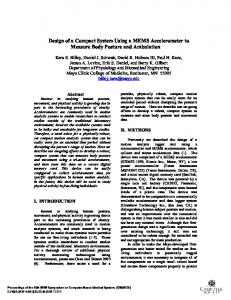
Design of a Compact, Low Complexity Scalable Phased Array Antenna Fatemeh Akbar and Amir Mortazawi noyan @umich.edu and amirm @eecs.umich.edu Department of Electrical Engineering and Computer Science University of Michigan, Ann Arbor, MI, USA Abstract array
-
A new approach for designing scalable phased
architectures
with
the
main
goal
of
reducing
their
complexity is proposed. This goal has been accomplished by devising a new technique, based on a vector summation method, to achieve beam steering. In this technique, the number of phase shifters, required in the phased array, are significantly reduced. As a proof of concept, a Ku band eight-element phased array with 40 degrees of scan range is presented. The designed phased array employs only two phase shifters. Index
Terms -
Phased
array,
vector
summation,
beam
steering, phase shifter, scan range.
I.
INTRODUCTION
An electronically controlled phased array consists of an array of antennas capable of beam forming and steering by adjusting the relative phase and amplitude of the signal received or transmitted by each antenna element [1]. Phased arrays provide spatial selectivity making them attractive for many telecommunication systems and radar applications. Phased arrays used in base stations can increase the channel capacity and data rate without requiring extra bandwidth, alleviate multipath fading and co-channel interference, and reduce the required transmit power in telecommunication system [2]. Phased arrays also enhance cross range resolution and signal to noise ratio in radar systems [2]. Unique features of phased array technologies are very useful in many commercial applications. However, the cost and complexity of phased arrays have prevented them to be widely utilized. Therefore, recently, researchers have been focusing on reducing the cost and complexity of the phased array systems to enable them to be widely used in commercial applications. Since phase shifters and their control circuitry play a significant role in determining the cost and complexity of phased arrays, recent publications describe new architectures to reduce the required number of phase shifters for beam steering [3]-[6]. In [3], radiating elements have been grouped into a number of sub-arrays where each sub-array utilizes a single phase shifter. The approach presented in [4] and [5] is based on the extended resonance technique for both power combining and phase shifting, which eliminates the requirement of employing a separate phase shifter per each antenna element in phased arrays. Reducing the number and size of phase shifters is important in the design of integrated phased arrays. For example, in [6], a variable-phase ring oscillator and phase locked loop architecture is used to eliminate phase shifters.
This paper presents a new technique to achieve phase shifting and beam steering in a modular phased array consisting of a number of sub-arrays. The required number of phase shifters decreases significantly in each sub-array. Sub arrays can be connected together to form a larger array. In the proposed design, only two phase shifters control the phase progression across eight antenna elements, while in conventional design of phased arrays, a separate phase shifter is required for each antenna element. Consequently, the complexity and size of the phased arrays utilizing the proposed design are reduced. Section II describes the design of the phased array. Section III describes the simulation and measurement results for the designed array operating at 12.4-12.8 GHz. The designed array consists of directional couplers, variable gain amplifiers, power combiners, and only two phase shifters. II.
PROPOSED PHASED ARRAY ARCHITECTURE AND ANALYSIS
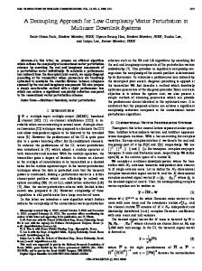
A. Proposed Architecture The circuit architecture for the four-antenna sub-array, employed in the design of the phased array, is shown in Fig. l. Operation of the sub-array is based on vector summation method where the excitation signal at each antenna port is the vector sum of two vector components [7], [8]. Depending on the phase difference between the two input vectors of each vector sum block and the relative amplitudes of these vectors, phase of the excitation signal for each antenna is determined. The inter-element phase difference, i.e. the phase difference between excitation signals of the adjacent antennas, determines the scan angle. In [7], vector summation approach AIIII
Alltz
II/pili Phllse Shijicr Fig. l. Architecture of the four-element sub-array based on a vector summation method.
978-1-4799-8275-2/15/$31.00 ©2015 IEEE
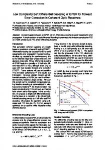
II/pili Fig. 2. Circuit diagram of the eight-element phased array based on a vector summation method.
has been utilized to realize an adjustable phase shift at each antenna port and to provide the required linear phase progression throughout the array for each scan angle. However, in [8], the phase progression in the entire eight element array is controlled by using two phase shifters. In the sub-array architecture, shown in Fig. 1, S, denotes the i-th (i 1, 2, 3, 4) vector sum block. The vectors B/s (i 1, 2, 3, 4) input to S/s have the same amplitude and phase cP with respect to the signal input to the phased array. The vector A/ input to S/ is from the gain stage G/. However, the other vectors input to S,'s, i.e. A,'s (i 2, 3, 4), are from the gain stages G,'s (i 2, 3, 4) amplifying the excitation signals EJ's (j =1, 2, 3) at the antenna ports. The variable gain amplifiers, denoted by VGA/s (i 1, 2, 3, 4), are responsible for controlling the amplitudes of the antennas' excitation signals at a given value of CP. E j, E2, E3, and E4 are given by: =
=
=
=
=
E1 E2 E3 E4
=
=
=
=
VGA1(Bej