280
IEEE SENSORS JOURNAL, VOL. 11, NO. 2, FEBRUARY 2011
Design of a Low-Consumption Fluxgate Transducer for High-Current Measurement Applications Guillermo Velasco-Quesada, Member, IEEE, Manuel Román-Lumbreras, Member, IEEE, Alfonso Conesa-Roca, and Felipe Jeréz
Abstract—This paper presents the design and final realization of a transducer system for the measurement of high dc and ac currents. This transducer is based on the magnetic flux compensation technique, also called fluxgate principle. The transducer designed can measure currents of around 1 kA of peak value with a 170-kHz small-signal bandwidth. This functionality can be achieved with low power consumption if the designed system is compared with other fluxgate transducers available on the market and with similar functional specifications. Improvement in consumption was achieved by the inclusion in the design of a switching power supply (based on flyback topology) and a switched amplifier for generating magnetic flux compensation current (based on half-bridge inverter topology).
TABLE I COMPARISON OF ELECTRIC CURRENT TRANSDUCERS
Index Terms—AC and dc current measurement, current transducer, magnetic field measurement.
I. INTRODUCTION ANY industrial applications require the measurement of electrical currents. These include current measurement for electric power and energy calculations, for feedback loops in control systems, and for security devices in order to guarantee human protection and prevent systems from malfunctioning or breakdowns. A more detailed description of systems and applications using current measurement can be found in [1]–[3]. Different methods for measuring electrical currents have been developed, and they have been based on physical principles (electrical, magnetic, or optical) or they take advantage of the behavior of some materials within a magnetic field [4]. The most suitable method for measuring electrical current depends, in each case, on the current characteristics: dc current, ac current, or both simultaneously, frequency ranges, expected peak or maximum value, accuracy, and need for isolation. The main methods used to measure electric currents are: shunt resistors, current transformers, Hall-effect transducers, Rogowski coils, fluxgate transducers, and magnetoresistors.
M
Manuscript received February 15, 2010; revised April 13, 2010; accepted June 18, 2010. Date of publication September 20, 2010; date of current version November 17, 2010. The associate editor coordinating the review of this manuscript and approving it for publication was Prof. Okyay Kaynak. G. Velasco-Quesada, M. Roman-Lumbreras, and A. Conesa-Roca are with the Electronic Engineering Department, Technical University of Catalonia, Urgell 187, 08036-Barcelona, Spain (e-mail:
[email protected];
[email protected];
[email protected]). F. Jeréz is with the PREMO Group, Conchita Supervía, 13 08028-Barcelona, Spain (e-mail:
[email protected]). Color versions of one or more of the figures in this paper are available online at http://ieeexplore.ieee.org. Digital Object Identifier 10.1109/JSEN.2010.2054831
Xiao et al. describe and compare some of these methods for electric current measurement [5], and Table I presents a comparison using the most relevant parameters for determining the main characteristics of each of them and their usual applications. Although fluxgate sensors first appeared in the early 1930s, these sensors are still being used in many applications [6]. Fluxgate transducers are widely used in dc or low-frequency current measurements, they offer a wide range of new applications and present a high potential for future applications [7]. The transducer described in this paper was jointly developed by the Technical University of Catalonia and the PREMO Group in order to meet identified needs in the sector of electric current measurement. It is a current transducer based on fluxgate technology providing a better performance with power supply and energy consumption requirements, in comparison with similar fluxgate transducers existing on the market. This transducer was previously introduced in [8], where its principle of operation and construction were briefly described, and some of its specifications were characterized. This new paper extends the contents reported in [8] with a detailed description of the transducer operating principle and its practical realization. II. FLUXGATE TRANSDUCER OPERATING PRINCIPLE The basic operating principle of these transducers is based on the detection of the saturation state of a magnetic circuit. More details can be found in the specialized literature [9]–[11].
1530-437X/$26.00 © 2010 IEEE
VELASCO-QUESADA et al.: LOW-CONSUMPTION FLUXGATE TRANSDUCER FOR HIGH-CURRENT MEASUREMENT APPLICATIONS
Fig. 1. Fluxgate transducer structures. (a) Standard structure. (b) Structure without gap on the magnetic path.
281
Fig. 3. Voltage excitation and current waveforms on auxiliary winding under: (a) zero flux condition (I = 0) and (b) nonzero flux condition (I > 0).
Fig. 2. Basic operating principle of fluxgate transducers. Fig. 4. Operating principle of the designed fluxgate transducer.
The so-called “standard” fluxgate transducer uses a toroidal magnetic circuit which includes an air gap with the element for magnetic field measurement. This sensing element is also called “saturable inductor” [Fig. 1(a)]. The current sensor proposed in this work is based on a variation of the “standard” fluxgate transducer structure, and it operates under closed-loop conditions. This kind of transducer uses its own ring core as a magnetic field detector and includes no gap on the magnetic path [Fig. 1(b)]. An auxiliary winding , (normally called excitation winding) is added to the core which is used as a saturable inductor for flux detection purposes. This structure of the fluxgate transducer is described with more detail in [11] and [12]. In order to obtain a null magnetic field on the magnetic circuit, must be excited with an appropriate a secondary winding current, as shown in Fig. 2. In this case, the transducer operates on zero-flux condition, and the current imposed on the secis directly proportional to the primary curondary winding . The primary winding is a single wire placed through rent the hole of ring core. The relationship between the primary and the secondary currents is shown in (1) is the number of turns of the secondary winding. where The detection of the zero-flux condition on the transducer magnetic circuit is performed by the change of the saturable inductor inductance value. In the absence of the primary current, the flux through the saturable inductor is zero. Under these conditions, if a square voltage waveform is applied to the exciwill be as shown in tation winding, the current waveform Fig. 3(a). effect on the excitation current The primary current implies a nonzero average value, as shown in Fig. 3(b). The average value and the sign of depend on the value and the direction of . These effects of the primary current on the excitation current are detailed in [11].
III. FLUXGATE TRANSDUCER DESIGN AND REALIZATION The designed transducer operates under closed-loop conditions, according to the general diagram shown in Fig. 2. A null value on the average current through the excitation winding is used to determine the zero-flux condition. This operating principle is presented in Fig. 4. One important drawback of this structure is the possibility of noise injection from the excitation winding circuit into the primary current circuit. This noise can be coupled into the primary current circuit due to the transformer effect present in the magnetic core of the transducer. The solution usually adopted, in order to avoid this negative influence, is the use of a second core with a new auxiliary winding (or new excitation winding). Under ideal conditions, these two cores and their winding must be identical [11] and [13]. and ) are excited If these two auxiliary windings ( with the same current but in opposite directions, then the two induced currents on the primary conductor will be equals and with opposite directions, cancelling their effects. In this new structure, a secondary winding (used for flux compensation) is common to both auxiliary cores. The transducer presented in this work is designed on the basis of this structure, and its block diagram is shown in Fig. 5. A more detailed description of different parts of this system is included in the paragraphs below. A. Signal Generator for Auxiliary Windings Excitation The basic self-oscillating circuit for exciting the auxiliary windings is presented in Fig. 6. It is a relaxation oscillator based on a Schmitt trigger and an RL circuit. The inductor used for this and a voltage oscillator is one of the excitation windings appears on the terminals proportional to excitation current . of the sensing resistor Excitation windings are formed by 200-turns coils on two toroidal cores. The internal and external diameter of each core is
282
IEEE SENSORS JOURNAL, VOL. 11, NO. 2, FEBRUARY 2011
Fig. 7. Block diagram of the control circuit.
Fig. 5. Block diagram of the designed fluxgate transducer.
Fig. 6. Circuit for auxiliary wiring excitation.
50 and 60 mm, respectively, and their square section is 64 mm . The material used for the cores is based on a nanocrystalline structure with iron base and high permeability, and the inductance of these two windings is about 300 mH. The trigger output voltage oscillates between high and low output levels when the current through excitation winding exceeds the adjusted threshold values. These threshold values are calculated in order to guarantee that the two excitation cores reach both saturation regions. In the designed transducer, these values are adjusted to 25 mA, approximately. The oscillation frequency of the oscillator circuit is influenced by the electric and magnetic characteristics of excitation cores, because one of them is included in the oscillator circuit. The self-oscillating frequency of the designed circuit is close to 300 Hz. The current driver for exciting both auxiliary windings is based on an integrated circuit which includes a dual monolithic high-speed power MOSFET driver. An accurate mathematical model of self-oscillating fluxgate current sensor can be found in [14]. B. Excitation Current Symmetry Detector As described in Section II, the excitation current average in the absence of primary current value is zero , and a nonzero primary current leads to a nonzero excitation current average value. The sign of the excitation current average value is related to the primary current direction.
For an automatic adjustment of the compensation current , the use of a PI controller is proposed. If the magvalue is equal and opposite to the flux netic flux generated by , the transducer operates generated by the primary current and the average under zero average flux condition is also zero. value of (the This control strategy is illustrated in Fig. 7, where total magnetic flux in one of the auxiliary cores) is obtained by the addition of three different fluxes: the magnetic flux generand the fluxes induced ated by the compensation wiring on the auxiliary core by the primary and the excitation currents and , respectively). ( and is noted by and The addition of the flows ) and a dc or low-frequency has an ac component (due to component (due to ). With this control scheme, the total magnetic flux average , and, consequently, the auxiliary current average value is always zero, as is demonstrated by the system value as transfer function, noted by
where (2)
indicates that only the The high-pass filter behavior of appears on the auxac component of the excitation current , ensuring that it has a zero average value. iliary current The described control loop cannot guarantee the correct operation of the transducer if the excitation cores are strongly saturated at the system startup. This condition can appear when a nonzero primary current is circulating through the transducer before it is turned on. As a consequence of strong saturation in the auxiliary core, the inductance of the auxiliary winding drops and then, the oscillation frequency of the self-oscillating circuit increases until reaching some tens of kilohertz. Under these conditions, the sign is independent of the primary current of the average value of direction. To avoid this important drawback, an additional feedback initial loop is included in the control system circuit. For all conditions, this new loop guarantees that zero-flux condition is reached when the transducer is switched on. The operation of this new loop is based on the property of mentioned previously: the frequency of the excitation current is
VELASCO-QUESADA et al.: LOW-CONSUMPTION FLUXGATE TRANSDUCER FOR HIGH-CURRENT MEASUREMENT APPLICATIONS
283
Fig. 9. (a) Continuous winding and (b) progressive winding techniques. Fig. 8. Excitation circuit for secondary current generation.
high when the transducer operates under high saturation conditions, but it is close to the self-oscillation frequency when the transducer operates near zero-flux conditions. As Fig. 5 shows, this loop includes a low-frequency triangular waveform generator, a frequency detector circuit and an analog switch controlled by the frequency detector circuit. The frequency detector circuit is based on a high- bandpass filter (tuned with self-oscillation frequency) and a voltage comparator as a peak detector. While the transducer does not operate near zero-flux condiis contion, the input of the current compensation driver nected to the low-frequency triangular waveform generator. The use of this waveform generates a current sweep through the compensation winding which guarantees reaching the zero-flux condition. When the transducer operates near zero-flux condiis near the self-oscillation frequency tion, the frequency of and the output of the frequency detector circuit is activated. Then, the analog switch connects the PI controller to the input of the current compensation driver. The utilization of this additional control loop increases the robustness of system because it ensures that the system will always reach zero-flux condition after transient situations. C. Valid Measure Indicator The output of the low-frequency detector circuit is connected to a valid measurement indicator circuit. This indication is actifrequency is close to the self-oscillating frevated when the quency, and this effect occurs when the transducer operates near zero-flux condition. The elements used for a valid measure indication are one light-emitting diode (LED) and one single-pole double-throw (SPDT) electromagnetic relay. D. Driver for Secondary Current
Generation
The traditional excitation circuits for secondary winding consist of a current driver based on linear amplifiers. For the implementation of the proposed transducer, a class-D amplifier has been used as a secondary current driver. These kinds of amplifiers are based on pulsewidth modulator (PWM) circuits and half-bridge inverters, as shown in Fig. 8. These amplifiers have the advantage of high energy efficiency, but they also include harmonic components related to its switching frequency.
The PWM circuit generates a square voltage waveform with a proportional to the PI controller or to the output duty cycle signal of the LF triangular waveform oscillator. This voltage is applied to the secondary winding through a current driver based on a half-bridge inverter. The current driver circuit is implemented with two N-channel-type MOSFETs and one on-chip integrated half-bridge gate driver. The switching frequency used is 50 kHz, because it is a frequency above the human acoustic threshold and it implies a neg. This current ripple can ligible secondary current ripple be estimated by (3) is the inductance of the secondary winding, is where is the driver the voltage applied to the secondary winding, is the duty cycle of the voltage switching frequency, and waveform generated by the PWM circuit. Secondary current ripple depends on the duty cycle value, and . In this case, (3) can it takes the maximum value when be rewritten as (4) For the designed transducer, the maximum value of the secondary current ripple can be estimated to be about 10 A. On the other hand, the number of turns of the secondary coil defines the sensor output voltage sensitivity, and its maximum value is limited by the effects of the parasitic self-capacitance on this coil [6]. The transformer winding capacitance is detrimental in three ways [15]: 1) it can drive the transformer into premature resonance; 2) it can produce large current spikes when operates from a square voltage source; and 3) it can produce electrostatic coupling to other circuits. The sensitivity of output voltage for the designed transducer is specified to 1000:1 (1000 A of primary current will be compensated with a 1-A secondary current). This specification implies the use of 1000 turns for the construction of the secondary coil. For this reason, the self-capacitance of secondary coil must be minimized using a careful design for the construction of this coil. One way to reduce the self-capacitance effect on toroidal coils is by means of a progressive winding technique, rather than the usual continuous winding technique [15]. Continuous winding and one example of a progressive winding technique are shown in Fig. 9.
284
IEEE SENSORS JOURNAL, VOL. 11, NO. 2, FEBRUARY 2011
Fig. 11. Designed fluxgate transducer.
IV. TEST RESULTS Fig. 10. Transformer and windings utilized on the designed transducer.
The progressive winding technique proposes to wind a certain number of turns in one direction (forward), then wind half of turns on the opposite direction (backward), and finally repeat this procedure until winding is completed. For example, in the case of designed transducer, the self-capacity in the secondary winding is reduced by a factor of 30 when the progressive winding technique is used instead of a continuous winding technique. Finally, the output voltage of the transducer is measured on a connected in series with secondary winding. shunt resistor coil and operThe circuit formed by the inductance of ates as a low-pass current filter, so the output voltage is proportional to the primary current.
E. AC Current Measurement Fluxgate transducers are only suitable for measurements of dc or low-frequency ac currents, because the maximum bandwidth which can be reached is around 100 Hz [7]. The maximum frequency for ac current measurements is imposed by the operating frequency of the zero-flux detection circuit. For medium or high-frequency ac currents measurement, and in order to improve the current sensor dynamic response, a third core is included on the transducer transformer [11]. This new as ring core is only embraced by the secondary winding shown in Fig. 10. The combination of this new core, the secondary winding, and the primary current wire operates exclusively as a conventional current transformer, and this feature guarantees medium and high-frequency current measurement.
Fig. 11 illustrates the final appearance of the designed transducer, where the main components of the system can be identified: measuring transformer, printed circuit board (PCB), and box to contain all of the transducer elements. In order to evaluate the performance of the designed transducer, some laboratory tests were conducted. This section presents the results obtained in some of these experimental tests. The first test consisted of full-scale dc current measurement, the second one determined the small-signal bandwidth of system, the third one evaluated the system response for high-level current transients, and, finally, the last test compared the power consumption between the designed system and one commercial fluxgate transducer from the leading company. A. DC Current Measurement For this test, the primary current was generated by a dc power source, and it was adjusted by a programmable dc active load. Primary current was measured by a noninductive shunt (20 A/60 mV), and its value was utilized as a reference. Furthermore, this current was coupled to the transducer through 30 turns, so that current measured by transducer was 30 times larger than the current measured by the shunt. Finally, the output resistor value utilized for this test was 1 . The following equation corresponds to the linear regression of the measured input-to-output current characteristic: (5) This result indicates good system linearity (0.999) and low offset error (around 10 mA). Fig. 12 shows the relative error in the measurement. This error is referred to the system full-scale. Accordingly with the obtained data, the relative error is around 0.2% in 700 A to 700 A range.
F. Transducer Power Supply
B. Small-Signal Bandwidth
Usually, bidirectional current transducers need a regulated and symmetrical bipolar voltage power supply (values of 15 V and 15 V are typical). In order to relax these specifications, the designed transducer incorporates a power supply based on a flyback dc/dc converter. This converter generates a stable output voltages ( 12 V and 12 V) from a single and unregulated input voltage, which can be between 10–30 V.
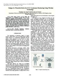
For this second test, the primary current was generated by a linear amplifier from a function generator. Primary current was measured by a shunt resistor, and this value was used as a reference. Furthermore, this current was coupled to the transducer through two turns, so that the current measured by the transducer was twice that of the current measured by the shunt. The frequency response of system under small-signal conditions is shown in Fig. 13. The primary current used for this
VELASCO-QUESADA et al.: LOW-CONSUMPTION FLUXGATE TRANSDUCER FOR HIGH-CURRENT MEASUREMENT APPLICATIONS
285
Fig. 14. Experimental waveforms of measured current for primary current step (from 0 to 600 A) and frequency: (a) 100 Hz and (b) 1 kHz.
Fig. 12. Measured relative output error of the designed transducer.
Fig. 15. Edge details of measured current for primary current step from 0 to 300 A.
around 20 A per microsecond. This slope on the current variation is imposed by the limitations of current generator utilized in this test and not by the dynamic response of the designed transducer.
Fig. 13. Small-signal frequency response of the designed transducer.
test was a sinusoidal waveform with 7 A of amplitude; this amplitude was the 1% of the transducer primary current nominal value. As can be seen, the small-signal bandwidth of the designed transducer can be estimated to be about 170 kHz. C. Transient Current Measurement This test was carried out in order to evaluate the response of the designed transducer to fast transitions on the primary current. A square waveform between 0–600 A was utilized as a primary current, and a 3- resistor was utilized as a shunt . For this resistor, and accordingly with (1), the resistor output voltage on the output shunt resistor can be calculated as (6) Fig. 14 shows the current measured by the designed transducer when the frequency of the primary current is 100 Hz and 1 kHz. Fig. 15 shows the details of rising and falling edges on the measured current when primary current is a square waveform between 0–300 A. The slope of these edges can be estimated to
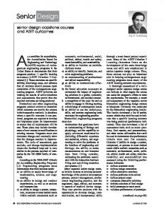
D. Power Consumption Fig. 16 shows the power consumed by the designed transducer as a function of the primary current. This figure also shows the power consumed by other fluxgate transducer available on the market and with similar characteristics to those of the designed transducer. Table II provides a summary of main features of transducers used in this comparative test. The experimental setup utilized to perform this test is the same as that used for the test described in paragraph 4.1. In this new test, the power consumption of the transducer under test was measured and stored by a digital power meter. Fig. 16 shows that the power consumed by the designed transducer is always smaller than the power consumed by the LEM transducer. The difference between consumptions is around 0.5 W for zero primary current, but this difference increases over 2 W for certain ranges of the primary current. These differences imply that the power consumed by the designed transducer is 15% lower in the whole measurement range, reaching 50% of the power consumed for some ranges of the primary current, as is shown in Fig. 17. Fig. 17 shows power consumption ratio of the LEM transducer with reference to the designed transducer consumption. This power ratio is represented versus the primary current value.
286
IEEE SENSORS JOURNAL, VOL. 11, NO. 2, FEBRUARY 2011
Fig. 16. Power consumptions of the designed transducer and other similar transducer versus the primary current value.
TABLE II MAIN FEATURES OF FLUXGATE TRANSDUCERS UTILIZED FOR TEST
(flyback topology). This strategy allows us to relax the specifications for supply voltage because only one unregulated power source is needed for the system power supply. On the other hand, the driver for generating the compensation current is also based on a high-efficiency switching converter (half-bridge inverter topology). These two design strategies allow the designed transducer to present lower power consumption than the other tested transducer. Experimental tests were conducted in order to verify the correct operation of the designed transducer and some of the obtained results are presented. Finally, the main characteristics of the designed transducer are summarized here. • Nominal primary current: 700 A. • Maximum peak primary current: 1 kA. • Conversion ratio: 1000:1. • Small-signal bandwidth (1% of nominal primary current): 170 kHz. • Supply voltage: from 10 to 30 VDC. : 3.1 W. • Standby power consumption In order to obtain a more detailed characterization of the designed current transducer, reference DCT-700 A can be consulted on the general datasheet of PREMO Group [1].1 Some parts of the presented transducer are protected by the Spanish patent referenced as P200701317. REFERENCES
Fig. 17. Power consumption ratio of compared transducers versus the primary current value.
V. CONCLUSION In this paper, the design of a current transducer based on fluxgate principle has been proposed and its final realization has been presented. The main objective of the transducer design is to improve the specifications of power supply system, maintaining the rest of specifications at the same level of other similar transducers available on the market. This objective was achieved through the use of a switching power supply based on high-efficiency dc/dc power converter
[1] “Power Electronics Inductive Components, General Catalogue,” PREMO Group, 2008. [2] “Industry Current & Voltage Transducers,” LEM Int. USA, CH 28100 E/US, 2008. [3] “Application Guide: Electrical Measurement in Automation Industry,” LEM Components, CH 25103 E, 2005. [4] J. Lenz and A. S. Edelstein, “Magnetic sensors and their applications,” IEEE Sensors J., vol. 6, no. 3, pp. 631–649, Jun. 2006. [5] C. Xiao, L. Zhao, T. Asada, W. G. Odendaal, and J. D. van Wyk, “An overview of integratable current sensor technologies,” in Proc. 38th IAS Annual Meeting Conf. Rec. Industry Applic. Conf., Salt Lake City, UT, Oct. 12–16, 2003, vol. 2, pp. 1251–1258. [6] P. Ripka, “Advances in fluxgate sensors,” Sens. Actuators A, Phys., vol. 106, pp. 8–14, 2003. [7] Kaluza, A. Grüger, and H. Grüger, “New and future applications of fluxgate sensors,” Sens. Actuators A, Phys., vol. 106, pp. 48–51, 2006. [8] M. Román, G. Velasco, A. Conesa, and F. Jeréz, “Low consumption flux-gate transducer for AC and DC high-current measurement,” in Proc. IEEE Power Electron. Specialists Conf., Rhodes, Greece, Jun. 15–19, 2008, pp. 535–540. [9] P. Ripka, “Review of fluxgate sensors,” Sens. Actuators A, Phys., vol. 33, pp. 129–141, 1992. [10] P. Ripka and M. Janosek, “Advances in magnetic sensors,” in Proc. IEEE Sensors Conf., Lecce, Italy, Oct. 26–29, 2008, pp. 1–4. [11] “Isolated Current and Voltage Transducers: Characteristics—Applications—Calculations (3rd Edition),” LEM Components, CH 24101 E/US, 2004. [12] P. Ripka, J. Kubik, M. Duffy, W. G. Hurley, and S. O’Reilly, “Current sensor in PCB technology,” IEEE Sensors J., vol. 5, no. 3, pp. 433–438, Jun. 2005. [13] T. Sonoda, R. Ueda, and K. Koga, “An ac and dc current sensor of high accuracy,” IEEE Trans. Ind. Appl., vol. 28, no. 5, pp. 1087–1094, Sep./Oct. 1992. [14] M. M. Ponjavic´ and R. M. -Duric´, “Nonlinear modelling of the selfoscillating fluxgate current sensor,” IEEE Sensors J., vol. 7, no. 11, pp. 1546–1553, Nov. 2007. [15] W. T. McLyman, Transformer and Inductor Design Handbook, 3rd ed. New York: Marcel Dekker, 2004, p. 532. 1Available.
Online: http://www.grupopremo.com.
VELASCO-QUESADA et al.: LOW-CONSUMPTION FLUXGATE TRANSDUCER FOR HIGH-CURRENT MEASUREMENT APPLICATIONS
Guillermo Velasco-Quesada (S’04–M’09) was born in Barcelona, Spain. He received the Ingeniero Técnico Industrial en Electricidad, the Ingeniero en Electrónica, and Doctor en Ingeniería Electrónica degrees from the Universitat Politècnica de Catalunya (UPC), Barcelona, Spain, in 1990, 2002, and 2008, respectively. Since 1992, he has been an Associate Professor with the Departamento de Ingeniería Electrónica, Escuela de Ingeniería Tecnica Industrial de Barcelona, UPC, Barcelona, Spain, where he teaches analog and power electronics. He is a Researcher with the Energy Processing and Integrated Circuits (EPIC) Group and the Power Electronics Research Center (PERC) of the UPC. His main research interest includes analysis, modeling and control of power systems for renewable energy applications, and grid-connected PV systems based on reconfigurable topologies. Dr. Velasco is a member of the IEEE Industrial Electronics and IEEE Power Electronics Societies.
Manuel Román-Lumbreras (M’09) was born in Gallur, Spain. He received the Ingeniero Industrial en Electricidad and the Doctor Ingeniero Industrial degrees from the Universitat Politècnica de Catalunya (UPC), Barcelona, Spain, in 1975 and 2006, respectively. From 1977 to 2000, he was an Assistant Professor with the UPC and, since 2001, he has been an Associate Professor with the Departamento de Ingeniería Electrónica, UPC. From 1965 to 2000, he was working in the industry in the area of electrical energy production, railway power traction systems, ac and dc motor drives, electric power quality, and power converters for uninterruptible power supplies and active power filters. His actual research interests are power electronics, electric power network quality, converters for renewable energy systems, and digital control of power converters. Dr. Roman is a member of the IEEE Industrial Electronics, IEEE Industrial Applications, and IEEE Power Electronics Societies.
287
Alfonso Conesa-Roca was born in Barcelona, Spain. He received the Ingeniero en Electrónica and Doctor en Ingeniería Electrónica degrees from the Universidad Politècnica de Catalunya (UPC), Barcelona, Spain, in 1998 and 2006, respectively. He is currently an Associate Professor with the Departamento de Ingeniería Electrónica, Escuela Universitaria de Ingeniería Técnica Industrial de Barcelona, UPC. His current research interests include switching-mode power supplies, power architectures, resonant conversion, and photovoltaic applications. Dr. Conesa is a member of the IEEE Sensors Council.
Felipe Jeréz was born in Málaga, Spain. He received the Industrial Tech Engineering degree from Málaga Technical University, Málaga, Spain, in 1994. Since 1995, he has been involved with R&D activities, first with PREDAN, where he was involved with RFID component and systems, in 2005 he was involved in R&D activities at PREMO China, and since 2006 he has been leading the R&D team of the PREMO Group, Barcelona, Spain, as CTO of the company. Recently, PREMO has been developing a new generation of products working very closely with universities in Barcelona (UPC, UB), Málaga (UMA), and Madrid (UPM). His main research areas includes power product development for automotive applications, especially for electric and hybrid vehicle, advanced current transducer applications, energy harvesting micro-devices, and RFID antennas for automotive applications.