This paper presents an advanced leg module developed for. HRP-2. HRP-2 is a new humanoid robotics platform, which we have been developing in phase two ...
3URFHHGLQJV�RI�WKH������,(((� ,QWHUQDWLRQDO�&RQIHUHQFH�RQ�5RERWLFV� �$XWRPDWLRQ :DVKLQJWRQ��'&����0D\������
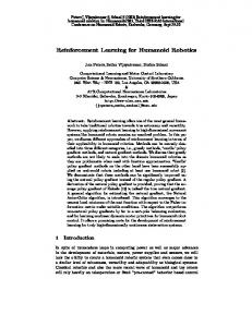
Design of Advanced Leg Module for Humanoid Robotics Project of METI Kenji KANEKO *1, Shuuji KAJITA *1, Fumio KANEHIRO *1, Kazuhito YOKOI *1, Kiyoshi FUJIWARA *1, Hirohisa HIRUKAWA *1, Toshikazu KAWASAKI *2, Masaru HIRATA *2, and Takakatsu ISOZUMI *2 *1: National Institute of Advanced Industrial Science and Technology 1-1-1 Umezono, Tsukuba, Ibaraki 305-8568, Japan *2: Kawada Industries, Inc. 122-1 Hagadai, Haga-machi, Haga-gun, Tochigi 321-3325, Japan E-mail: {k.kaneko, s.kajita, f-kanehiro, kazuhito.yokoi, k-fujiwara, hiro.hirukawa}@aist.go.jp {toshikazu.kawasaki, m.hirata, taka.isozumi}@kawada.co.jp
WABIN-RII, which has a total of 43 D.O.F., is 1890 [mm] height, 902 [mm] width, and 131.4 [kg] weight respectively. WABIN-RII has a completely humanoid figure with two legs, two arms, two hands, and two eyes, and is capable of walking and even dancing. H6 and H7 are humanoid robots constructed by University of Tokyo [2]. H6 is 1370 [mm] height and 590 [mm] width respectively, and has a total of 35 D.O.F. Its weight is 55 [kg], since aircraft technologies were applied to the body frame, which led to a strong and light structure. H6 and H7 can walk up and down 25 [cm] high steps and can also recognize pre-entered human faces. JOHNNIE is an anthropomorphic autonomous biped robot constructed by Technical University of Munich for realization of dynamically three-dimensional walking and jogging motion [3]. JOHNNIE with 17 D.O.F. is expected to be about 1800 [mm] height and about 37 [kg] weight respectively, while the operating power is supplied by external sources. Since the manufacturing process is in progress, JOHNNIE is just going to walk. MK.5 is a compact size humanoid robot with 24 D.O.F. constructed by Aoyma Gakuin University, and 356 [mm] height and 1.9 [kg] weight respectively [4]. Its concepts are compact, low-priced, expansible, and mobile humanoid robot. To realize it, all joints are driven by servo modules for radio controlled model like PINO constructed by ERATO [5]. MORPH, that is a succeeding model of MK.5 and is currently constructed by ERATO, will appear with high mobility. Another compact size humanoid robot is SDR-3X (Sony Dream Robot-3X) [6]. The reason Sony made SDR-3X as small as possible is that the smaller it is, the lower the cost becomes. Its specifications are 500 [mm] height, 220 [mm] width, 5 [kg] weight, and 24 D.O.F. SDR-3X can more than just walk around such as squatting, getting up, and doing synchronized choreography, though it can’t go up and down stairs since Sony developed it for entertainment. The most impressive humanoid robot should be HONDA humanoid robots. When P2, the second prototype HONDA
Abstract This paper presents an advanced leg module developed for HRP-2. HRP-2 is a new humanoid robotics platform, which we have been developing in phase two of HRP. HRP is a humanoid robotics project, which has been lunched by Ministry of Economy, Trade and Industry (METI) of Japan from 1998FY to 2002FY for five years. The ability of the biped locomotion of HRP-2 is improved so that HRP-2 can cope with rough terrain in the open air and can prevent the possible damages to a humanoid robot’s own self in the event of tipping over. In this paper, the mechanisms and specifications of leg module, electrical system, simulation results utilized for deciding specifications, and experimental results are also introduced.
1. Introduction The traditional robots are typically used for industrial automation and play in environments that are separated from the sphere of human lives and activities. However, the need for robots has recently been changed from industrial automation to human friendly robot system. Coming the increasingly aging societies, robots that assist human activities in human daily environments such as in offices, homes and hospitals are expected. Especially, an emergence of humanoid robots is strongly expected because of anthropomorphism, friendly design, applicability of locomotion, behavior within the human living environments, and so on. To meet these demands, several humanoid robots have been developed in these years. One of them is WABIAN (WAseda BIpedal humANoid) constructed by Waseda University [1]. WABIAN is succeed by WABOT-1 (WAseda roBOT-1), which is the world’s first life-sized humanoid robot constructed in 1973 by late Prof. KATO’s laboratory. It is no exaggeration to say that he was a pioneer in the development of humanoid robot and WABIAN is the orthodox humanoid robot. The newest WABIAN:
������������������������������,(((�
38
humanoid robot, was revealed in 1996 after ten years secret research, the robotics world was stunned. P2 is the world’s first cable-less humanoid robot, which can walk and can go up/down stairs [7]. Downsizing P2 (1820 [mm] height, 600 [mm] width, 210 [kg] weight including batteries, 6 D.O.F./Leg, 7 D.O.F./Arm, 2 D.O.F./Hand), P3 (1600 [mm] height, 600 [mm] width, 130 [kg] weight including batteries, 6 D.O.F./Leg, 7 D.O.F./Arm, 1 D.O.F./Hand) appeared in 1997 with the same mobility as P2 [8]. In 2000, further downsizing P3, ASIMO that stands for Advanced Step in Innovative Mobility appeared with children-size (1200 [mm] height, 450 [mm] width, 43 [kg] weight including batteries, 6 D.O.F./Leg, 5 D.O.F./Arm, 1 D.O.F./Hand, 2 D.O.F./Head) and new walking technology (i-WALK) [9]. The introduction of i-WALK technology allowed ASIMO to walk continuously while changing directions, and gave the robot even greater stability in response to sudden movements. It is no exaggeration to say that the great success of HONDA humanoid robot makes the current research on the world’s humanoid robot to become very active area. The credit for a success of these humanoid robots nearly goes to the zero moment point (ZMP) theory invented by Prof. Vukobratovic [10]. He is also one of the inventors for anthropomorphic mechanisms and biped locomotion. The ZMP theory is effective in making humanoid robots walk with gait stabilization. The more humanoid robots which can walk and can go up/down stairs are developed, the more humanoid robots are expected to perform several application tasks in an actual human living environment. However the application area of humanoid robots has still limited to the amusement and the entertainment. For research and development of humanoid robot performing application tasks, Ministry of Economy, Trade and Industry (METI) of Japan has launched a humanoid robotics project (HRP) [11]. The project is run from 1998FY to 2002FY for five years, consisting of phase one for the first two years and phase two for the last three years. In phase one (FY 1998-1999), a humanoid robotics platform (HRP-1), a tele-existence cockpit to control humanoid robots, and an equivalent virtual robot including dynamic simulator [12] were developed. In phase two (FY 2000-2002), research and development are carried out on the applications of humanoid robots (maintenance tasks of industrial plants, human care, tele-operations of construction machines, security services of home and office, and cooperative works in the open air) using HRP-1. Improvement and addition of elemental technologies are also carried out in phase two. This paper presents an advanced leg module developed for HRP-2. HRP-2 is a new humanoid robotics platform, whose manufacturing process is currently in progress in phase two of HRP. HRP-2 has two great peculiarities, which are especially necessary for cooperative works in the open air. One is that the ability of the biped locomotion of HRP-2 is improved so that HRP-2 can cope with rough terrain in the open air. The other is that HRP-2 is designed in order to prevent tipping over easily. In this paper, the mechanisms and specifications of leg module, simulation results utilized for deciding specifications, and experimental results are also introduced.
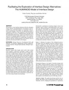
2. HRP-2: Humanoid Robotics Platform - 2 HRP-2 is a new humanoid robotics platform, whose manufacturing process is in progress in phase two of HRP. The design concepts of HRP-2 are light, compact, but performable for application tasks like cooperative works in the open air shown in Fig. 1 [13]. As a result, HRP-2 is feminine size and it is expected to be 1500 [mm] height and 60 [kg] weight.
Figure 1. Cooperation Works in the Open Air In this section, HRP-2L, which is a leg module for HRP-2, is introduced. The details of designs are presented in later sections.
2.1. Specifications of HRP-2L Figure 2(a) shows an overview of developed leg module for HRP-2 and (b) shows its kinematical design, respectively. 574
358
91
1412.9 945
300
300
120
Cantilever Type Structure
190
(a) Developed HRP-2L
(b) Configuration
Figure 2. Leg Module for HRP-2 As shown in Fig. 2, HRP-2L has a unique configuration. It means that the hip joint has a cantilever type structure. The reason we designed so will be explained at Section 3.1. Table 1 shows the specifications of HRP-2L.
39
Table 1. Specifications of Leg Module for HRP-2 6 D.O.F./Leg ( Hip:3 Knee:1 Ankle:2) Upper leg length: 300 [mm] Lower leg length: 300 [mm] Ankle length: 91 [mm] Length between hip joints: 120 [mm] Weight Legs: 8.6 [kg/leg] u 2 [legs] = 17.2 [kg] Batteries: 11.4 [kg] Controller Box: 7.0 [kg] Dummy Weights: 22.6 [kg] Total: 58.2 [kg] Legs
Hip (Pitch) Knee (Pitch) Ankle (Pitch)
Hip (Pitch) Knee (Pitch) Ankle (Pitch)
2.2. Working Angle of Leg Joint
Yaw
-45 deg. to
45 deg.
Roll
-45 deg. to
20 deg.
Pitch
-125 deg. to 15 deg.
Knee
Pitch
-0 deg. to 130 deg.
Ankle
Pitch
-45 deg. to
20 deg.
Roll
-20 deg. to
30 deg.
-0 deg. to 108 deg. -21 deg. to
0 deg.
-89 deg. to
0 deg.
-0 deg. to 150 deg. -110 deg. to
0 deg.
(b) Sitting on the Floor
The working angle of leg joint for HRP-2L is designed as follows. First, we design that to be about the same as that of standard human shown in Table 2 [14], because of making humanoid robot perform human tasks as well as human.
Hip
0 deg.
(a) Taking a Seat
Looking at Fig. 2 and Table 1, it is apparent that the light and compact leg module was completed.
Table 2. Working Angle of Standard Human
-135 deg. to
Hip (Pitch) Knee (Pitch) Ankle (Pitch)
+ YAW ROLL
-67 deg. to
42 deg.
-0 deg. to
97 deg.
-67 deg. to
42 deg.
-81 deg. to
25 deg.
(c) Walking Straight
+ PITCH
Hip (Pitch) Knee (Pitch) Ankle (Pitch)
+ PITCH
ROLL + PITCH
However, the data on working angle of standard human is not sufficient for humanoid robot and we should increase that for design of humanoid robot. One reason is that the kinematical design of HRP-2L is not same as human. For example, the humanoid robot does not typically have limber motions like a motion made by the human backbone. To cover the limber motion, the joints existed in humanoid robot should work more extensively (see Fig. 2(a)). The other reason is that we request the humanoid robot to perform the motions that are impossible for human. One of examples is a sitting on the floor in Japanese style (see Fig. 2(b)). To re-design the working angle of humanoid robot, we simulated the humanoid robot, which performs the following five motions: 1: Taking a seat 2: Sitting on the floor in Japanese style (see Fig. 2(b)) 3: Walking Straight with 400[mm] Steps 4: Going up Stairs with 200[mm] Height per Step 5: Going down Stairs with 200[mm] Height per Step, using a dynamical model of humanoid robot [14]. These five motions are basic motions in human daily environments. By combining the simulation results (Fig. 3) and the standard human data (Table 2), as a result, the working angle of leg module for HRP-2 was derived as shown in Table 3.
-0 deg. to 113 deg. -60 deg. to
-9 deg.
-60 deg. to
-9 deg.
(d) Going up Stairs
Hip (Pitch) Knee (Pitch) Ankle (Pitch)
-0 deg. to 113 deg. -81 deg. to
(e) Going down Stairs Figure 3. Basic Five Motions (Left Side) and Requested Working Angle (Right Side) Table 3. Working Angle of Leg Module Hip
Yaw
-45 deg. to
45 deg.
Roll
-45 deg. to
20 deg.
Pitch
-135 deg. to 42 deg.
Knee
Pitch
-0 deg. to 150 deg.
Ankle
Pitch
-100 deg. to 42 deg.
Roll
40
-20 deg. to
35 deg.
25 deg.
appropriately shape the support polygon for the phase of double supported legs by selecting the landing point of swing leg. Closing legs further enables to make the support polygon to be on the opposite side of Fig. 4(c) as shown in Fig. 4(d). Consequently, the stable walk would be achieved by constructing the mechanism that enables to have a wide sphere of landing point for swinging leg. By shaping the support polygon for the phase of double supported legs immediately, the tipping over would be prevented, even if humanoid robot begins to tip over. To realize a wide sphere of landing point for swinging leg, the hip joint of HRP-2L has a cantilever type structure as shown in Fig. 2. The reason is that the cantilever type structure enables to have less collision between both inside upper-limbs and also enables to cross legs. The other factor throwing the humanoid robot off balance is caused from rolling motion of gait. The mechanism, which makes the trajectory of the center of gravity (COG) of upper body smooth with less rolling motion, is also effective in the prevention of tipping over. To reduce rolling motion of gait, the cantilever type structure also plays an important. Since the cantilever type structure can make the length between hip joints shorter, this structure enables to make the length between landing points of pitch axis shorter too. Figure 5 shows the simulation results on rolling motion of gait with regard to landing points. It can be observed that the smoother with less rolling motion is achieved by the shorter length between both landing points of pitch axis. In the real leg module for HRP-2, the length between hip joints is designed to be 120 [mm].
3. Mechanical Design As mentioned in former section, the design concepts of HRP-2 are light, compact, but performable for application tasks like cooperative works in the open air. To realize HRP-2, several distinctive mechanisms are employed. In this section, the details of mechanical design are introduced.
3.1. Mechanism for Prevention of Tipping Over The humanoid robot tends to tip over easily, since the area of foot sole that supports the whole body is so small and limited. The motion of not only body but also arms during tasks also makes it easy to throw the humanoid robot off balance. The mechanism for prevention of tipping over is a very important achievement to realize a humanoid robot. The tipping over easily occurs when the target ZMP is outside of the support polygon made by supported legs (and/or leg). Since it is so hard to recover tipping over when the target ZMP is outside of the support polygon, our first approach to prevent tipping over is to construct the mechanism, which easily enables to make the target ZMP to be inside of the support polygon. The support polygon is illustrated in Fig. 4 and it can be defined as follows. Supported Leg
Walking Direction
Supported Leg
Walking Direction
Heel Land Support Polygon
Swing Leg
(a) Single Supported Leg Supported Legs
Walking Direction
Support Polygon
Swing Leg
Landing Point and Walking Direction
(b) Landing at Heel Point Supported Walking Legs Direction
Trajectory of COG of Upper Body
Support Polygon
Swing Leg
Support Polygon
Swing Leg
(a) Length between Landing Points of Pitch Axis: 65 [mm]
(c) Double Supported Legs (d) Closing Legs Figure 4. Support Polygon Landing Point and Walking Direction
When the humanoid robot stands on one leg, the support polygon is the same as a sole of supported leg as shown in Fig. 4(a). During standing on double legs, the support polygon is defined as an outline made by supported legs. If the swing leg with a rectangular sole lands at the heel and the sole of supported leg is also rectangular, the support polygon is pentagonal in the almost case as shown in Fig. 4(b), though it has a possibility to be quadrilateral or hexagonal according to a landing condition. When all rectangular sole supports the humanoid robot, the support polygon is hexagonal in the almost case as shown in Fig. 4(c), though it has also a possibility to be pentagonal or rectangular according to a relation between the two soles. From this point of view, we can
Trajectory of COG of Upper Body
(b) Length between Landing Points of Pitch Axis: 100 [mm] Figure 5. Analysis Results on Trajectory of COG of Upper Body in the Horizontal Plane
41
From these discussions, the mechanism for the prevention of tipping over is achieved by the cantilever type structure as shown in Fig. 2. This structure enables to cross legs as well as to make a protector between legs for minimal damage in the event of tipping over.
DC Motor with Ironless Rotor Pulley
Harmonic Drive Gear
Timing Belt
3.2. Mechanism for Rough Terrain Pulley
For a practical use, the humanoid robot should walk not only on a flat floor but also on a rough terrain. To design the mechanism for rough terrain, our goals were set up so that the humanoid robot can cope with rough terrain, whose slope is less than 5 [%] and whose irregular is within 40 [mm] per one step. To realize our goals, the torque control of foot sole is very important. The reason is that the dynamic equations are written based on torque. HRP-2L has a mechanism shown in Fig. 6 at each foot part. Its mechanism is formed from a six-axis force sensor and rubber bushes. Since the rubber bushes equivalently implement compliance elements along the roll and pitch axes, the control system of torque imposed on foot sole can be achieved by controlling its rotational deformations with using a six-axis force sensor [15]. This mechanism also has a compliance element in the vertical direction. These compliance elements are also effective in reducing the landing impact force and torque.
Figure 7. Mechanism of Drive System employed for HRP-2L
3.4. Structural Design for Light Weight The weight of the structural parts is quite significant. From a design experience [16], the proportion of structure weight to total weight of humanoid is more than 60 [%]. The weight of screws is also significant, since 20 [%] of the overall weight are due to screws [3]. A shortcut to make humanoid robot lighter can be achieved by reducing the weight of structural parts. The first approach to realize a structural design for light weight was carried out by casting several links. Figure 8 shows the cast links for HRP-2L. Its material is magnesium alloy, since the specific gravity of magnesium alloy is 68 [%] of that of aluminum alloy.
Six-Axis Force Sensor
Rubber Bush
Figure 8. Magnesium Cast Links The design experience [16] also reveals that about 15 [%] of the overall weight are due to Harmonic Drive gears. The second approach to realize a structural design for light weight was carried out by employing new Harmonic Drive gears. Figure 9(a) shows general Harmonic Drive gear and (b) shows new Harmonic Drive gear. The weight of the new one is about 35 [%] of the general one. Furthermore, comparing with the general one, its thickness is about half, though its diameter is 15 [%] bigger. Using the new Harmonic Drive gears, about 1 [Kg] reduction could be achieved at assembling HRP-2L. The compact and light joints could then be constructed.
Foot Sole Plate
Figure 6. Mechanism for Rough Terrain
3.3. Mechanism of Drive System HRP-2L has several rectangular axes joints. As shown in Fig. 2, the hip joint consists of three rectangular axes, while the ankle joint consists of two rectangular axes. To realize them, a compact design for mechanism that enables to construct rectangular axes joint was employed. Figure 7 shows an element of compact design and the mechanism of drive system used in all joint of HRP-2L. Its mechanism is formed from DC motor, pulleys, timing belt, and Harmonic Drive gear. Since Harmonic Drive gear is used as the final reduction and pulleys are used between output axis of DC motor and input axis of Harmonic Drive gear, the transmission error caused on elasticity of timing belt can be ignored.
(a) General Harmonic Gear (b) New Harmonic Gear Figure 9. Harmonic Drive Gear
42
3.5. Selection of Actuator and Reduction Ratio The selection of actuator and reduction ratio is an important issue in the design of a humanoid robot. The reason is that the more powerful actuators are selected, the heavier humanoid is constructed and furthermore the more powerful actuators are required. To optimize the selection of actuators and reduction ratios, iterations of mechanical design, simulation analysis on control system, and applying the real system are necessary [3], [16]. We carried out several simulation analyses on humanoid robot motions including five basic motions defined in Section 2.2. One example of simulation analyses is shown in Fig. 10. These analysis results are obtained from simulating dynamically humanoid robot going up stairs with 200 [mm] height per step and 1.5 [sec/step] in speed. Figure 10(a) shows the time response of joint torque of pitch axis, (b) is angular velocity of pitch axis, and (c) is consumed power of pitch axis. These responses tell us the guideline to decide the hardware specifications such as actuators, reduction ratio of gears and that of pulleys. By comparing the data appeared on catalog of actuators and that obtained from several dynamic simulations, we finally decided the hardware specifications on actuators and Harmonic Drive gears as shown in Table 4. The reason DC motors were selected is related with electrical design for light weight and will be explained at Section 4.1. Since the final reduction ratio can be decided by the selection of pulleys as shown in Fig. 7, the reduction ratio of pulleys is slightly modified via several experiments.
(a) Joint Torque of Pitch Axis
(b) Angular Velocity of Pitch Axis
4. Electrical Design In the electrical design for HRP-2L, several efforts for light weight and realization of compact body were adopted. In this section, the details of electrical design are introduced.
4.1. Servo Driver Module To realize humanoid robot using electrical actuators, servo drivers are necessary. Since the humanoid robot has high D.O.F., the volume of servo drivers is significant issue for construction of compact humanoid. To overcome this issue, compact servo driver module was developed for HRP-2L. Before introducing developed servo driver module, we must clarify the kind of electrical actuator for HRP-2L. In general, several types of electrical actuators such as DC motors, brush-less motors, and stepping motors are active in the robotics area. From the view of compact design of servo driver, DC motor would be nice comparing with others. The reason is as follows. For instance, when constructing a H-bridge servo driver, four transistors or MOS-FETs are necessary for controlling one DC motor, but six transistors or MOS-FETs are necessary for one brush-less motor. It means that servo driver for DC motor can be made compacter. This is a reason we selected DC motors for HRP-2L.
(c) Consumed Power of Pitch Axis Figure 10. Analysis Results when going up Stairs with 200[mm] Height per Step and 1.5[sec/step] in speed
Table 4. Actuators and Harmonic Drive Gears used in HRP-2L Joint Actuator Ratio of Harmonic Hip Yaw DC 20 [W] 1:160 Roll DC 90 [W] 1:160 Pitch DC 90 [W] 1:120 Knee Ankle
43
Pitch Pitch Roll
DC 150 [W] DC 90 [W] DC 70 [W]
1:160 1:160 1:160
Figure 11 shows the developed DC motor driver module, which enables to control two DC motors independently. Using six modules, all joint of HRP-2L can be controlled. Its size is 95 [mm] length, 65 [mm] width, and 15 [mm] depth including some projections and a plate of heat conduction, respectively. It is enough compact to install several modules inside of body of humanoid, even if high D.O.F. are requested. Table 5 tells us that it also has a powerful output for controlling HRP-2L.
Table 6. Specifications of HRP Interface Board Bus Type PCI DA 16 Channel 12-Bit AD 12 Channel 12-Bit Counter 16 Channel 24-Bit Up/Down Counter DIO 16 Channel Input, 16 Channel Output Size ( LuWuH ) 176 [mm] u 99 [mm] u 22 [mm] Weight 160 [g] A DA converter unit controls 12-axes input command voltages for DC motor driver. An AD converter unit controls 3 axes acceleration sensors and 3 axes angular velocity sensors. From the outputs of these sensors, the posture of humanoid robot is calculated. A counter unit, which is connected with 12-axes rotary encoders, is occupied with measuring each joint angle. A DIO unit controls relays, LEDs, and safe system.
Figure 11. DC Motor Driver Module for 2-Axes
4.3. Quad Force Sensors Interface Board
Table 5. Specifications of DC Motor Driver Module Controllable Axes 2-Axes independently Supply Voltage 48 [V] Maximum Output Voltage r 48 [V] Maximum Output Current r 20 [A] Input Command Voltage r 10 [V] Control Mode Current Control Size ( L u W u H ) 95 [mm] u 65 [mm] u 15 [mm] Weight 120 [g] including plate of heat conduction
To construct stable walking controller, ZMP information is very important. A 6-axes force sensor is needed at each foot sole for calculation of ZMP. Especially, a digital force sensor is suitable for humanoids because of compact design without external amplifier and controllability such as less noise and less load to main CPU. However a digital force sensor requires an interface board. Since humanoid has at least two force sensors on dual foot soles, many interface boards are necessary. This issue is significant at installing boards into the limited space of bus-rack. To overcome this issue, we are developing Quad Force Sensors Interface Board, though we currently use two single port F/T sensor I/F boards (ISA) for two 6-axes force sensors mounted on both foot soles of HRP-2L. Figure 13 shows the developing Quad Force Sensors Interface Board and it will be employed for HRP-2 after several tests using HRP-2L.
4.2. HRP Interface Board To control humanoid robot through a computer bus, several kinds of function board such as DA, AD, counter, and Digital Input/Output are necessary. These function boards are currently on sale as any products. However, these products are not sufficient for HRP-2L, since they have few channels and/or few functions on the same board. Although there are some few boards which have multi-functions on the same board, the number of channels and/or functions are not yet sufficient for HRP-2L. As long as these products are installed into the bus rack, a lot of products are necessary and compact humanoid robot can not be constructed. The other reason is that PCI bus, which is faster than ISA bus, accepts only four boards without a bus-bridge. To overcome these issues, we have developed HRP interface board. Figure 12 shows HRP interface board developed for HRP-2L with multi-D.O.F. As shown in Table 6, there are multi-channels and multi-functions, which are sufficient for controlling HRP-2L, on one board.
(a) Front (b) Back Figure 13. Quad Force Sensors Interface Board (PCI)
4.4. Battery and Sensors HRP-2L has a Ni-MH battery (48.0 [V], 18 [Ah]) inside of its body. The weight of the battery is 11.4 [kg]. This power supply system is designed so that HRP-2 works for about 60 minutes, though it depends on motions. To calculate the ZMP, a 6-axes force sensor of digital type is mounted on each foot sole as shown in Fig. 6. A 3-axes acceleration sensor and three angular velocity sensors are mounted inside of HRP-2L’s body. These sensors are so important that HRP-2L can’t walk stably without them.
(a) Front (b) Back Figure 12. HRP Interface Board (PCI)
44
4.5. Computer System The realtime controller runs on a CPU board (Pentium III, 933 [MHz]) in the body of HRP-2L. The operating system is ART-Linux [17]. ART-Linux enables the execution of realtime processes at the user level so that users can implement realtime applications as if they are non-realtime ones. This feature of ART-Linux is essential for realizing the identical controller for the simulation and the real robot [18].
[2]
[3]
[4]
5. Experiments [5]
The basic experiments were carried out to confirm whether HRP-2L can actually make motions like steps. Figure 14 shows the experimental results on HRP-2L’s steps. In these results, same parts of AIST controller for Honda humanoid [19] were just used for confirmation of HRP-2L’s motions. Looking at Fig. 14, it is apparent that a posture variation of roll axis is less than 1 [deg.]. It is also observed that the single supported phase for right leg and that for left leg are very regularly switched and HRP-2L could make steps stably. We could confirm that HRP-2L was successfully developed.
[6]
[7]
[8]
[9]
[10]
[11]
[12]
Figure 14. Experimental Results on HRP-2L’s Steps [13]
6. Conclusions [14]
This paper presented how we developed the advanced leg module for HRP-2, which copes with rough terrain in the open air. Several distinctive mechanisms such as mechanism for prevention of tipping over and mechanism for rough terrain are employed for HRP-2. This paper also presented the detail of mechanism design, electrical design, specifications of leg module, simulation results utilized for deciding specifications, and experimental results. Future works include more walking experiments in the open air. The developments of whole HRP-2, a more stable balance controller, a cooperation controller between arms and legs, and an integration of vision system will also be investigated in the future.
[15]
[16]
[17]
[18]
References [1]
[19]
J. Yamaguchi, E. Soga, S. Inoue, and A. Takanishi, “Development of a Bipedal Humanoid Robot – Control Method
45
of Whole Body Cooperative Dynamic Biped Walking,” Proc. IEEE Int. Conference on Robotics and Automation, pp. 368-374, 1999. K. Nishiwaki, T. Sugihara, S. Kagami, F. Kanehiro, M. Inaba, and H. Inoue, “Design and Development of Research Platform for Perception-Action Integration in Humanoid Robot: H6,” Proc. Int. Conference on Intelligent Robots and Systems, pp. 1559-1564, 2000. M. Gienger, K. Löffler, and F. Pfeiffer, “Towards the Design of Biped Jogging Robot,” Proc. IEEE Int. Conference on Robotics and Automation, pp. 4140-4145, 2001. T. Furuta, Y. Okomura, and K. Tomiyama, “Design and Construction of a Series of Compact Humanoid Robots and Development of Biped Walk Control Strategies,” CD-ROM Proc. IEEE-RAS Int. Conference on Humanoid Robots, 84.pdf, 2000. F. Yamasaki, T. Matsui, T. Miyashita, and H. Kitano, “PINO The Humanoid that Walks,” CD-ROM Proc. IEEE-RAS Int. Conference on Humanoid Robots, 80.pdf, 2000. Y. Kuroki, T. Ishida, J. Yamaguchi, M. Fujita, and T. Doi, “A Small Biped Entertainment Robot,” Proc. IEEE-RAS Int. Conference on Humanoid Robots, pp. 181-186, 2001 K. Hirai, “Current and Future Perspective of Honda Humanoid Robot,” Proc. IEEE/RSJ Int. Conference on Intelligent Robots and Systems, pp. 500-508, 1997. K. Hirai, M. Hirose, Y. Haikawa, and T. Takenaka, “The Development of Honda Humanoid Robot,” Proc. IEEE Int. Conference on Robotics and Automation, pp. 1321-1326, 1998. M. Hirose, Y. Haikawa, T. Takenaka, and K, Hirai, “Development of Humanoid Robot ASIMO,” Proc. Int. Conference on Intelligent Robots and Systems, Workshop2 (Oct. 29, 2001), 2001. M. Vukobratovic and D. Juricic, “Contribution to the Synthesis of Biped Gait,” IEEE Tran. On Bio-Medical Engineering, Vol. 16, No. 1, pp. 1-6, 1969. H. Inoue, S. Tachi, Y. Nakamura, K. Hirai, N. Ohyu, S. Hirai, K. Tanie, K. Yokoi, and H. Hirukawa, “Overview of Humanoid Robotics Project of METI,” Proc. the 32nd Int. Symposium on Robotics, pp. 1478-1482, 2001. Y. Nakamura, et al., “V-HRP: Virtual Humanoid Robot Platform,” CD-ROM Proc. IEEE-RAS Int. Conference on Humanoid Robots, 86.pdf, 2000. K. Yokoyama, J. Maeda, T. Isozumi, and K. Kaneko, “Application of Humanoid Robots for Cooperative Tasks in the Outdoors,” Proc. Int. Conference on Intelligent Robots and Systems, Workshop2 (Oct. 29, 2001), 2001. Y. Kagawa., “Bio-Engineering Technical Terms Dictionary,” Japanese Standards Association, ISBN 4-542-20125-2, (in Japanese). K. Kaneko, K. Komoriya, K. Ohnishi, and K. Tanie, “Accurate Torque Control for a Geared DC Motor based on an Acceleration Controller,” Proc. Int. Conf. on Industrial Electronics, Control, Instrumentation, and Automation, Vol. 1, pp. .395-400, 1992. K. Kaneko, S. Kajita, K. Yokoi, V. Hugel, P. Blazevic, and P. Coiffet., “Design of LRP Humanoid Robot and its Control Method,” Proc. IEEE Int. Workshop on Robot-Human Interactive Communication, pp. 556-561, 2001. Y. Ishiwata and T. Matsui, “Development of Linux which has Advanced Real-Time Processing Function,” Proc. RSJ Annual Conf., pp. 355-356, 1998 (in Japanese). F. Kanehiro, N. Miyata, S. Kajita, K. Fujiwara, H. Hirukawa, Y. Nakamura, K. Yamane, I. Kohara, Y. Kawamura, and Y. Sankai, “Virtual Humanoid Robot Platform to Develop Controllers of Real Humanoid Robots without Porting,” Proc. Int. Conference on Intelligent Robots and Systems, pp. 1093-1099, 2001. K. Yokoi, F. Kanehiro, K. Kaneko, K. Fujiwara, S. Kajita, and H. Hirukawa, “A Honda Humanoid Robot Controlled by AIST Software,” Proc. IEEE-RAS Int. Conference on Humanoid Robots, pp. 259-264, 2001.