Aug 15, 2000 - the receiver's sensitivity on background noise power and on the characteristics of .... ratio, the modulation extinction ratio, and the bit-error rate.
TMO Progress Report 42-142
August 15, 2000
Design of an Opto-Electronic Receiver for Deep-Space Optical Communications G. G. Ortiz,1 J. V. Sandusky,1 and A. Biswas1
An opto-electronic receiver (detector and pre-amplifier) necessary to meet the demands of high capacity deep-space missions is designed for a Mars–Earth optical communication link. The receiver requirements are driven by link performance (data rate, bit-error rate, and margin), delivered power, pulse width, background signal, telescope quality, and atmospheric effects. Meeting these requirements becomes challenging as mission range and demand for link capacity increase. In this article, the detector’s characteristics (e.g., quantum efficiency, noise, gain, and diameter) are designed to address these various requirements. The dependence of the receiver’s sensitivity on background noise power and on the characteristics of the avalanche photodiode detector (APD) is analyzed. The improvement in optoelectronic receiver sensitivity is quantified for improvements in APD quantum efficiency, ionization factor, and bulk dark current. It is also found that, as the background signal increases, the improvement in receiver sensitivity from an improved detector is diminished due to the quantum noise limit. An opto-electronic receiver is designed based on a silicon APD to meet the mission link requirement of a pulse-position-modulated (M = 256) 30-kb/s data-rate (with a bit-error rate of 10−5 ). Improvements to the APD detector are also studied to describe a design that would achieve over 50-kb/s data rates for a Mars–Earth optical communication link.
I. Introduction JPL and NASA plan to develop a fully functional deep-space optical receiver (DSOR) to support optical communication needs [1]. The DSOR detects a pulse-position-modulated (PPM) signal from the spacecraft with an avalanche photodiode detector (APD), whose signal then is amplified and processed to extract the data. The front-end detector is the critical component of this direct-detection optical communication deep-space receiver. The detector must maintain low noise as it converts the signal photons into an electrical signal that can be post-processed to obtain the communication signal. The figure of merit used for this conversion (also called the receiver sensitivity) is determined by the detector’s quantum efficiency, intrinsic gain, and noise characteristics. Furthermore, in order to deliver a receiver capable of making a free-space link with high data rates and a low bit-error rate (BER), the detector must minimize background noise and atmospheric effects by controlling its collection area. 1 Communications
Systems and Research Section.
The research described in this publication was carried out by the Jet Propulsion Laboratory, California Institute of Technology, under a contract with the National Aeronautics and Space Administration.
1
The opto-electronic receiver detector and pre-amplifier specifications will be derived from analysis of the dependence of the receiver’s performance on background noise and of the detector’s characteristics and their impact on the link design constrained by mission link performance goals. Also, analysis of the estimated amount of background light that would be collected during daytime operation by an optical telescope on the Earth’s surface supporting an optical downlink from a Mars orbiter will be presented. Estimates of the blur circle for the different telescopes being considered also will be presented, as will simulation results on the receiver sensitivity for state-of-the-art detectors. The opto-electronic receiver is designed for a reference Mars mission. The transmitter baselined for implementing such a communication link is a Q-switched Nd:YAG laser [2]. The specifications of the transmitter are given in Table 1. From the receiver’s point of view, a certain level of the transmitted photons (received power) must be collected to detect the pulse. This level is determined from the values in Table 1 and the particular communication link design goals/requirements. This usually is stated in a design control table for the communication link. In the design of the opto-electronic receiver for this article, the values summarized in Table 2 will be used.
II. Opto-Electronic Deep-Space Receiver Design The major factors to consider in the design of the opto-electronic receiver are detector size (diameter), speed, and sensitivity. The size of the detector must be large enough to efficiently collect the photons but not so large that it detrimentally increases noise or reduces bandwidth. The major design drivers on
Table 1. Spacecraft transmitter specifications.
Parameter
Specification
Laser type
Q-switched Nd:YAG
Output power
1W
Downlink wavelength
1064 nm
Pulse width
25 ns
Modulation extinction ratio
10−5
Telescope diameter
10 cm
Transmitter optics losses
28 percent
Modulation format
PPM (M = 256)
Coding
Reed–Solomon
Table 2. Link design parameters.
Parameter
Specification
Required link margin
3 dB
Data rate
30 kb/s 10−5
Bit-error rate Link range
2 AU (300 million km)
Atmospheric losses
32.8 percent
Slot width
31.25 ns
Receiver telescope optics losses
2
55.1 percent
the size of the detector are the blur circle and the bandwidth requirements. The speed of the receiver is dominated by the capacitance of the detector. The major driver for the speed is the desired data rate and the pulse width of the received signal. The sensitivity of the opto-electronic receiver must be sufficient to provide the required link margin. Many factors influence the sensitivity—for example, detector quantum efficiency, gain, and noise characteristics. The drivers for a sensitive design are also numerous, such as link design, background signal, BER, wavelength, and detector characteristics. All these factors will be considered in the design of the opto-electronic receiver described in this section.
A. Size The diameter of the detector needs to be specified such that it collects all the focused energy that has been received by the optical telescope. But, this goal is hampered by the fact that the focus of the spot is not diffraction limited, due to the influence of atmospheric turbulence. This extended spot, for a desired percentage of encircled energy, is also known as the blur circle. In Appendix A, the relationships showing the dependence of the focus spot size on atmospheric turbulence are obtained.
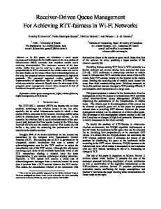
Figure 1 is a contour plot of the fraction P (r) of the incident energy collected within the normalized detector diameter, 2a, as a function of the normalized radius, r = a/λF , and normalized telescope diameter, D/r0 . Consider a telescope having a circular entrance pupil of diameter D and a system focal ratio F . A typical nighttime value of atmospheric coherence length r0 is 10 to 20 cm, corresponding to an atmospheric seeing disk radius, λ/r0 , of approximately 5 to 10 µrad (1 to 2 arcsec) at λ = 1.06 µm. Typical daytime values for r0 are 5 to 10 times smaller [3]. Unfortunately, the statistical dependence of r0 on solar zenith angle, observation zenith angle, and season is not well documented in the literature, especially for solar zenith angles corresponding to daytime operations. For the purpose of discussion, then, it is assumed that coherence cell sizes of interest range from 20 cm (nighttime) to 2 cm (daytime).
NORMALIZED TELESCOPE DIAMETER, D / r 0
500 0.1 0.2 0.3 0.4 0.5 0.6 400
0.7 0.8 0.9
300
200
100
0
100
200
300
400
500
NORMALIZED DETECTOR RADIUS, a / lF Fig. 1. Contours showing the fraction of the incident energy encircled as a function of the normalized detector radius and the differing ratios of telescope diameterto-atmospheric coherence cell size.
3
The detector diameter size necessary to encircle 80 percent of the energy can be obtained from Fig. 1. For example, Fig. 1 shows that, if the telescope diameter is 3.5 m and is operated under daytime conditions, r0 = 2 cm, a normalized detector radius of r = 160 will be required to encircle 80 percent of the signal. If the system focal ratio is F = 2, the corresponding detector diameter would be 2a = 680 µm. Table 3 lists these diameters for three telescope apertures. The actual size of the telescope then can be selected to meet the link objectives. Using the daytime condition to obtain the required detector diameter yields the benefit that the percentage of encircled energy in less severe turbulence will be higher. For example, during nighttime operation, the typical coherence cell size is 20 cm, which would cause over 98 percent of the energy to fall within the diameter of the same detector. Of course, to encircle a larger percentage of the energy during daytime conditions requires the detector diameter to increase. Table 3. Detector diameter for various telescope aperture sizes.a
Telescope aperture diameter, m 1 3.5 10
Detector radius, normalized aλ/F
Required detector diameter, mm
50
0.20
160
0.68
460
2.0
a Assuming
a wavelength of 1064 nm, a focal ratio of F = 2, 80 percent encircled energy, and an atmospheric coherence cell size of 2 cm (daytime).
B. Speed and Detector Selection As seen in Section II.A, the detector’s diameter must be very large to mitigate the effects of atmospheric turbulence. The speed requirements for the detector are based on the 25-ns downlink pulse width. Therefore, a detector with a 2.5-ns rise/fall time (90 to 10 percent) is sufficient to respond to the incoming pulse modulations. In practice, this is a relatively moderate speed requirement. The sensitivity of the detector selected needs to be the highest possible. The device parameters that impact sensitivity are quantum efficiency (QE) (1064 nm for this communication link), noise characteristics, and gain to amplify the signal. The sensitivity required for the link in this article will be derived in Section II.C. The photo-multiplying tube (PMT), the fiber-optical pre-amplifier (OA), and the avalanche photodiode detector (APD) were considered as the front-end component in the design of this receiver. The photomultiplying tube was found to have extremely high gain, but low quantum efficiencies at 1064 nm. Fiber-optical pre-amplifiers were found to provide high gain, but had small collection areas. The APD was selected as the front-end component in this receiver design, based on the availability of devices with high QEs, low-noise, and sufficient gain at our wavelength of interest. C. Sensitivity The sensitivity of the opto-electronic receiver is dependent on a large number of parameters. The major factors are background noise power, detector characteristics, modulation format, and pre-amplifier equivalent noise density. These in turn have their sub-dependencies. The background signal level is affected by the telescope receiver aperture diameter, the receiver optical efficiency, any optical filtering, the detector field of view, any light sources in the field of view, and the background irradiance (or spectral radiance). The APD detector dependencies are QE, gain, ionization ratio, bulk current, and surface current. The modulation format parameters have been set by the choice of link design outlined in Section I. These format details include the PPM format, the modulation slot width-to-dead time 4
ratio, the modulation extinction ratio, and the bit-error rate. In this subsection, the receiver sensitivity required to meet the link requirements will be obtained. First, a bound for the estimated background noise power will be derived; then the opto-electronic receiver sensitivity dependence on the dominant terms of background signal and detector characteristics will be explored. This subsection will conclude by obtaining the receiver design necessary to meet the link objectives. 1. Background Noise Power. Background noise power, broadly defined, is any non-signal photon exciting the detector of an optical system. Previous work [4,5] has enumerated the various sources of background light and shown that diffuse sky brightness and sunlight scattered from the surface of Mars (Marslight) will be its chief constituents for a Mars optical downlink. For this reason, the discussion of background light will be restricted to these two sources. In Appendix A, the amount of background light is estimated for these two sources in order to bound the estimated level of noise power incident on the detector. The typical diffuse sky radiance, E, is approximately 10 mW/m2 /sr/nm at 1.06 µm for clear skies [5]. Measured sky radiance at λ = 0.667 µm varies by at least a factor of four with the portion of sky examined [8] because sky radiance increases sharply close to the Sun [3]. The variation likely will be greater at longer wavelengths that are less likely to scatter and, therefore, provide a less isotropic diffuse sky radiance. For this reason, the sky brightness curve in Fig. 2 should be interpreted as a a range of sky brightness that depends strongly on the minimum Sun–Earth–probe angle. The flux entering the normalized detector is independent of the telescope diameter. Although a larger telescope captures more diffuse skylight, the increase is compensated by the reduction in field of view (FOV) for a fixed focal ratio. Table 4 summarizes the typical number of diffuse sky background photons for the three detector choices being considered in the design. Figure 3 shows the number of Mars background counts per nanosecond as a function of telescope diameter and normalized detector radius. For r = 160 (corresponding to a 3.5-m-diameter telescope collecting 80 percent of the signal energy during daytime conditions), less than 1 photon per nanosecond is collected. It is evident in Fig. 3 that, for a fixed telescope diameter, the background from Marslight ceases
PHOTON FLUX, photons per slot
30
20
10
RANGE OF TYPICAL SKY BRIGHTNESS
0 0
100
200
300
400
500
NORMALIZED DETECTOR RADIUS, a / lF Fig. 2. The typical number of diffuse sky background photons collected versus the normalized detector size.
5
Table 4. Diffuse sky background for various detector sizes.a
Detector radius, normalized aλ/F
Diffuse sky background, photons/ns
50
0.1
160
1–3
460
6–25
a The
optical filter bandwidth is 0.2 nm, and the wavelength is 1060 nm.
10 9
6
TELESCOPE DIAMETER, m
8 5 7
4
6
3
5
2
4 1 3 2 1
SLOT WIDTH = 1 ns FILTER BANDWIDTH = 0.2 nm
0 0
100
200
300
400
500
NORMALIZED DETECTOR RADIUS, a / lF Fig. 3. Contours showing the number of Mars background photons/ns for different telescope diameters and detector sizes.
to increase beyond the normalized detector diameter at which the detector’s field of view encompasses Mars entirely. There is a corresponding effect for a fixed normalized detector diameter as a function of increasing telescope diameter. Although the detector’s normalized diameter is fixed, its field of view decreases with increasing telescope aperture. The decrease in detector field of view exactly compensates the increased telescope collection aperture, and the collected Marslight becomes independent of telescope diameter. In both cases, it is assumed that the seeing limit is smaller than the angular diameter of Mars at favorable opposition so that a reasonably uniformly filled image is formed. The background signal level of Marslight is tabulated in Table 5 for the three telescope diameters under consideration. Because the Marslight calculations are done when Mars is at favorable opposition (0.4-AU Mars–Earth distance), the value estimated for the Marslight background represents the upper bound of the signal from the planet. The plots presented in this subsection scale linearly for different slot durations and spectral filter passbands. For example, if the slot duration were increased to 31.25 ns, corresponding to the receiver 6
considered for this link, the typical collected diffuse skylight and Marslight would increase 31.25 times to 31.25 photons per slot and 18.8 photons per slot, respectively, for a 3.5-m telescope. If the spectral filter passband were 2 nm instead of 0.2 nm, the typical collected diffuse skylight and Marslight would increase another 10 times to 313 photons per slot and 188 photons per slot, respectively. The two sources of background signal can be summed to obtain a bound on the estimated background signal (see Table 6) that would be incident on the detector. The lowest level is obtained during nighttime conditions, which is when the contribution from the diffused sky is negligible (typically 3 to 5 orders of magnitude smaller than its daytime value). In this case, the background signal is dominated by the planet (Mars) being in the field of view. For daytime conditions, the level is the sum of the planet light and the diffused sky. The two conditions are tabulated to demonstrate the dependence on telescope diameter and detector radius. These values represent the lower and upper values estimated for the background noise power for a Mars link. In a complete background noise power analysis, with varying orbital scenarios, the signal levels will vary with range and SEP angle. Table 5. Marslight signal for various detectors.a
Telescope aperture diameter, m
Detector radius, normalized aλ/F
1 3.5 10
Marslight background, photons/ns
50
0.1
160
0.6
460
5
a The
optical filter bandwidth is 0.2 nm, and the wavelength is 1060 nm.
Table 6. Total background signal for nighttime and daytime conditions for various detector/telescope combinations.a
Telescope aperture diameter, m 1 3.5 10
Detector radius, normalized aλ/F 50
Total night background, photons/slot 3
Total day background, photons/slot 6–24
160
19
31–94
460
156
344–938
a The
optical filter bandwidth is 0.2 nm, the wavelength is 1064 nm, the receiver slot width is 31.25 ns, and Mars is in the field of view.
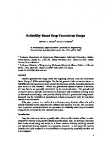
2. Sensitivity Dependence on Background Signal. The existence of background noise power on the detector has the effect of reducing the sensitivity of the receiver system. This is demonstrated in Fig. 4, where the receiver power required to make the link with our APD-based receiver is plotted. This receiver sensitivity calculation is done using the direct-detection link parameters from Section I (e.g., BER = 10−5 , slot width = 31.25 ns, and λ = 1064 nm) and with silicon APD parameters (QE = 0.38, k = 0.02, maximum gain = 100, surface current = 100 nA, and bulk current = 10 pA). The √ pre-amplifier used in this design is a high-impedance type with a noise equivalent current of 0.13 pA/ Hz. These parameters represent state-of-the-art devices available from commercial sources. The analysis was done using a model based on Gaussian statistics [6] for the APD and implemented in a spreadsheet for ease of use [7]. 7
RECEIVER REQUIRED SIGNAL, photons/pulse
103
QE = 0.38, k = 0.02
QUANTUM NOISE LIMITED
102
10 m
DEVICE NOISE LIMITED 101 1m 10-2
10-1
100
101
BER = 10-5 PPM (M = 256) 3.5 m pulse width = 25 ns slot width = 31.25 ns 102
103
104
BACKGROUND SIGNAL, photons/slot Fig. 4. Receiver sensitivity dependence on background signal. Bands show the range of background signal for a given receiver aperture.
Figure 4 shows the dependency of the receiver sensitivity as a function of background noise power. As expected, for high levels of background signal the sensitivity becomes quantum noise limited, while at low levels the performance is device noise limited. In this figure, the range of background signal levels estimated for the three telescope aperture diameters being considered is superimposed. The range indicated by the bar for each telescope size represents the amount of background signal involved in going from nighttime to daytime conditions (see Table 6 for values). It is clear that for larger telescope diameters the performance of the opto-electronic receiver tends to be quantum noise limited. 3. Sensitivity Dependence on Detector Device Parameters. As mentioned earlier, the sensitivity of the opto-electronic receiver depends strongly on the detector device characteristics. In this subsection, this dependence is demonstrated in order to determine the device characteristics that can offer the biggest benefit to improve overall sensitivity. In Fig. 5, the dependence of the receiver sensitivity is graphically plotted for the four important detector characteristics of quantum efficiency, ionization factor, bulk dark current, and surface dark current. The overall improvement benefit to the sensitivity is summarized in Fig. 6 for nighttime operations (low background signal). Here it is seen that the biggest benefit (up to 4 dB) would come from an increase in the quantum efficiency of the front-end detector. The second biggest percentage gain would come from improving the ionization factor. This says that it would benefit from amplifying the signal photoelectrons while not multiplying the noise. Reducing the ionization factor by an order of magnitude would result in over 2 dB of improvement in the receiver sensitivity. The bulk dark current could yield a 1.5-dB improvement if it were reduced from 10 to 1 pA, but little is gained in further reductions of this noise source. As the background signal is increased (e.g., daytime operations), the improvement on the receiver sensitivity from an improved detector is diminished due to the quantum noise limit. In Fig. 7, this result is illustrated using three devices: (1) the state-of-the-art high-QE silicon APD (QE = 0.38, k = 0.02), (2) a low-k APD (QE = 0.38, k = 0.007), and (3) an ideal APD (QE = 0.98, k = 0.00002). As mentioned
8
RECEIVER REQUIRED SIGNAL, dBm
-60 -61
(b)
(a)
-62 -63 -64 -65 -66 -67 -69 -70
k = 0.02 k = 0.002 k = 0.0002 k = 0.00002
MAX GAIN = 100 MAX GAIN = 1000
-68
10-5
10-4
10-3
10-2
10-1
0.001
RECEIVER REQUIRED SIGNAL, dBm
IONIZATION FACTOR, k -60 -61 -63
0.1
1
10
100
BULK DARK CURRENT, pA
k = 0.02 k = 0.002 k = 0.0002 k = 0.00002
(c)
-62
0.01
(d)
-64 -65 -66 -67
k = 0.002 k = 0.02
-68 -69 -70 0.3
0.4
0.5
0.6
0.7
0.8
0.9
1.0
0.1
1
10
100
1000
SURFACE CURRENT, nA
QUANTUM EFFICIENCY
Fig. 5. Receiver sensitivity dependence on the (a) ionization factor, (b) bulk dark current, (c) quantum efficiency, and (d) surface current, at low background signal levels.
in the previous paragraph, for low background signals, the low-k device shows over 2 dB of improvement in receiver sensitivity as compared with the state-of-art device. However, as the background signal increases, that improvement is significantly reduced. For example, with a 10-m-diameter telescope under daytime operations, the receiver required signal level would reduce from 440 to 400 photons/pulse to make the same link. This represents only a 0.4-dB improvement in the receiver sensitivity for a 2-dB improvement in device characteristics. This same effect also is seen for an ideal APD as compared with the state-of-the-art silicon APD. A potential 10-dB improvement in sensitivity due to improvement in device characteristics, at very low background signal levels, is reduced to an improvement of about 3 dB at high background signal levels due to the quantum noise limit. 4. Link Design/Sensitivity Requirement. In this subsection, the link design will be summarized and the opto-electronic receiver sensitivity necessary to make the communications link will be obtained. In order to determine the required receiver sensitivity, it is necessary to determine the received signal. This is done by the use of a power link budget (see Table 7). In the power link budget, all aspects of the link that affect the transmission of signal power are tracked in order to arrive at the detector received signal level. As stated in Section I, the link data-rate objective is 30 kb/s. Calculating the signal received with a 10-m telescope and using all stated link characteristics,
9
RECEIVER SENSITIVITY IMPROVEMENT, dB
5
0.98
4
0.00002 0.0002
0.78
3
0.002 2
0.58
0.1 0.01 1
1
0.38
0
0.02
10
QUANTUM IONIZATION BULK DARK EFFICIENCY FACTOR CURRENT, pA
RECEIVER REQUIRED SIGNAL, photons/pulse
Fig. 6. Receiver sensitivity improvement from APD device parameters, at low background signal levels.
QE = 0.38, k = 0.02 QE = 0.38, k = 0.007 QE = 0.98, k = 0.00002
103
QUANTUM NOISE LIMITED 102
DEVICE NOISE LIMITED
10 m BER = 10-5 PPM (M = 256) 3.5 m pulse width = 25 ns 1m slot width = 31.25 ns
101
10-2
10-1
100
101
102
103
104
BACKGROUND SIGNAL, photons/slot Fig. 7. Receiver sensitivity dependence on detector characteristics for three APD devices.
10
Table 7. Typical power link budget for a Mars–Earth optical communication link with a 10-m telescope receiver aperture.
Parameter Link range
Value
Notes
Link budget
2.99 × 10⁸ km
2.00 AU
—
3.00 ×
101
PPM (M = 256)
—
1.00 × 10⁻⁵
Reed–Solomon coding
—
Transmit power
1.00 W average
9.37 kW (peak)
69.72 dBm
Transmit losses
72.2% transmission
—
−1.41 dB 107.24 dB
Data rate Coded BER
Transmitter gain
kb/s
18.9 µrad beamwidth
—
Pointing losses
—
—
−2.01 dB
Space loss
—
—
−370.96 dB
67.2% transmission
—
−1.72 dB
10.00-m aperture diameter
—
149.23 dB
47.4% transmission
—
−3.24 dB
6.46 × 10² photons/pulse
4.83 nW (peak)
−53.16 dBm
—
—
−3.00 dB
3.23 × 10² photons/pulse
2.42 nW (peak)
−56.16 dBm
Atmospheric losses Receiver gain Receiver optics losses Received signal Required link margin Required sensitivity
a received signal level of 646 photons/pulse is obtained. Subtracting the required 3-dB link margin, this leads to an opto-electronic receiver sensitivity requirement of 323 photons/pulse. With the state-of-the-art silicon APD as the front-end detector, the required sensitivity to make the link is met as long as the background signal is below 400 photons/slot (see Fig. 8). This is possible under nighttime operations and in daytime when the Sun is not close to the field of view of the telescope, thereby keeping the sky radiance low. Therefore, a 30-kb/s optical link can be made to Mars using the state-of-the-art silicon APD that is commercially available. If operation is restricted to nighttime operations, then the data rate of the link can be increased to 46 kb/s for this same detector. Figure 8 also shows that the data rate would be reduced to 20 kb/s if the receiver were to experience the highest daytime background noise power. Also, if smaller diameter telescopes were used, the data rate would be reduced due to the reduction in received signal power available to the detector. To improve the receiver performance beyond these values, improvements in detector characteristics need to be pursued. The analysis of Section II.C.3 showed that the sensitivity would see the most improvement by increasing the quantum efficiency and by reducing the ionization factor. Two approaches have been proposed. One involves using the silicon-based device with the same QE (0.38) and reducing the ionization factor to a value of 0.007. The second approach involves the use of the naturally higher QE (>0.90) InGaAs material and improving its ionization coefficient to a value