Special DAC Section
Design of Asynchronous Circuits Using Synchronous CAD Tools Alex Kondratyev
Kelvin Lwin
Cadence Berkeley Laboratories
Reshape Inc.
Poor CAD support hinders wide acceptance of asynchronous methodologies, and asynchronous
■
the cost of switching to the new methodology, including training time, development of new libraries, and time spent dealing with CAD tool immaturity.
design tools are far behind synchronous commercial tools. A new design flow, NCL_X, based entirely on commercial CAD tools, targets a subclass of asynchronous circuits called null convention logic. NCL_X shows significant area improvement over other flows for this subclass. EDA FLOWS are industry driven, and thus use synchronous methodologies as de facto standards. However, implementation problems arise from imposing a synchronous model of operation on deep-submicron circuits. This problem motivates the investigation of other, asynchronous, modes of operation. Acceptance of new design methodologies, including asynchronous ones, by engineering and industrial communities depends on three major issues: ■
■
2
added value of the methodology in terms of area, power, speed, electromagnetic interference (EMI), noise immunity, and so on; tradeoffs, which design parameters often worsen to achieve added values, such as speed versus power, and area versus EMI; and
0740-7475/02/$17.00 © 2002 IEEE
Researchers have demonstrated that asynchronous designs can deliver higher speeds because they can latch values as the computation finishes, unlike synchronous design, which must wait for all computations to finish before latching. This improves overall performance when the average case finishes much earlier than the worst case.1 Researchers have also shown that, because of the absence of a clock and natural support of idle mode, such designs might consume less power than synchronous designs.2,3 Finally, asynchronous designs incur low EMI and noise, thanks to their even time distribution of switching activities.4 (See the “Practical asynchronous circuits and tools” sidebar for another perspective on asynchronous design from a leading expert in the field.) Nevertheless, industry acceptance of asynchronous designs has been slow because most success stories have thus far not delivered everything they’ve promised. Asynchronous high-speed circuits are custom designs,1 incorporating complicated timing assumptions about circuit delays and thus blurring the boundary between asynchronous and synchronous styles. CAD support for such methodologies is even more problematic than for custom synchronous designs. Thus, low-power asynchronous circuits usually compromise by using asynchronous methIEEE Design & Test of Computers
Practical asynchronous circuits and tools Alain J. Martin, California Institute of Technology After looking like a pipe dream for many years, asynchronous technology is becoming a viable—and perhaps unavoidable—alternative to clocked design for large VLSI systems. Asynchronous technology rests on local communications among concurrent units. Handshake protocols implement communication and synchronization among those units. There is no concept of global time—no clocks—and no assumptions about the duration of an action or communication. Asynchronous circuits have several advantages: ■
They avoid all issues related to distributing a clock signal reliably and efficiently across a large chip. ■ Because they can be largely insensitive to delay variations, asynchronous circuits can tolerate large variations in a design’s physical parameters, which are difficult to control in deep-submicron technology. ■ They offer, to the designer of low-power systems, automatic and perfect shut-off of idle parts. ■ Asynchronous technology lends itself to high-level synthesis and modular design. The asynchronous community has made spectacular progress in the last decade, and today we know how to design correct and efficient asynchronous circuits. The correctness issue mostly concerned designing glitch-free circuits. The efficiency issue related to the cost of handshake protocols and completion detection. To appreciate this progress, consider the family of asynchronous chips designed at the California Institute of Technology between 1989 and 1999. Researchers at Caltech designed the world’s first asynchronous microprocessor in 1989. The chip had 20,000 transistors and was a simple 16-bit machine. Its peak performance was 5 MIPS at 2 V drawing 10 mW, and 18 MIPS at 5 V drawing 225 mW, in 1.6-micron CMOS. It was correct on first silicon, and its performance was competitive with designs of that time.
ods for control synthesis and synchronous methods for data path design. Communication among these circuit elements rests on timing assumptions and delay-matching mechanisms. The latter makes verifying such circuits difficult. To further complicate the situation, a lack of commercial CAD support for asynchronous July–August 2002
In 1994, Caltech presented an asynchronous, pipelined lattice structure filter, the first example of very fine pipelining. The chip had 250,000 transistors. In 0.9-micron CMOS and at 3.3 V, the throughput was 130 MHz—that is, 500 million 12-bit additions or multiplications per second. In liquid nitrogen, the filter executed 1 billion operations per second. The chip worked correctly from 1 V to 5 V. At 1.1 V, it operated at 36 million operations per second and consumed 20 mW. Between 1995 and 1998, Caltech researchers designed the MiniMIPS, an asynchronous MIPS R3000. As of today, it is still the most efficient asynchronous chip ever designed. The R3000 is a classic 32-bit RISC processor with two 4Kbyte caches. Caltech fabricated the chip in 0.6-micron CMOS. The transistor count was 2 million. All chips were functional, except one with a defective package. The test performance on small programs was 180 MIPS and 4 W at 3.3 V, 100 MIPS and 850 mW at 2.0 V, and 60 MIPS and 220 mW at 1.5 V. The performance figures running Dhrystone benchmarks were 185 MHz at 3.3 V (165 VAX MIPS). So, if researchers have resolved most of the issues regarding the design of asynchronous circuits, why is the industry so slow in adopting the technology? There are certainly sociological and other nontechnical answers to the question. But Kondratyev and Lwin are correct in identifying the absence of design tools as the single most important technical stumbling block. As long as there is no market for asynchronous EDA tools, the EDA industry will not create these tools. But as long as there are no tools for asynchronous design, there will be no market for the tools! Kondratyev and Lwin aim to break free from this vicious cycle by adapting existing tools to the asynchronous design flow. Whether they can accomplish this without too high a performance penalty remains to be seen. But the experiment is worth watching. Alain J. Martin is a professor of computer science at the California Institute of Technology. Contact him at
[email protected].
synthesis sometimes forces designers to use inhouse specification languages and design tools.2,3 This chronic deficiency is a major roadblock to wider acceptance of asynchronous methodologies. Low EMI and noise coefficients are the only “free” advantages of asynchronous circuits.
3
Special DAC Section
Without the clock, noise and EMI spectrums are significantly flatter across the entire frequency domain. For noise, this can be a 10-dB drop, according to McCardle and Chester.4 Until recently, EMI and noise metrics were second-class citizens; everybody focused on power and performance. But EMI and noise metrics are garnering more attention because of two emerging applications: mixed-signal design and smart cards. In the former, analog functions are particularly sensitive to clock-correlated, digitalswitching noise. Reducing noise and EMI significantly boosts both precision and performance. In smart cards, EMI doesn’t affect functionality but has a significant impact on security. Noninvasive security attacks depend on monitoring a smart card’s power rail, or EMI signature, to decipher information on the card. Even distribution of circuit-switching activities vastly improves security. We propose an automatic design flow for asynchronous circuits, with the following features: ■ ■ ■
Its added value rests on its low EMI and/or higher security level. This value comes at the expense of an area penalty. The flow has low switching costs because it closely mimics the conventional synchronous hardware description language (HDL) methodology and relies on commercial design tools.
The last feature is key for asynchronous design. It removes the roadblock of reeducating designers and shifts the criteria for choosing whether to use asynchronous circuits toward an objective estimation of their tradeoffs: area, speed, power, and so on. This new design flow, NCL_X, targets a subclass of asynchronous circuits called null convention logic (NCL).
selves in terms of logical equations (Boolean algebra). In general, synchronous designers don’t need to worry about the exact sequence of gate switching as long as the outputs are correct at the clock pulses. In contrast, asynchronous circuits must strictly coordinate their behavior. Logic synthesis for asynchronous circuits not only must handle circuit functionality but also must properly order gate activity (switching). The solution is to use functional redundancy to explicitly model computation flows without using abstract means such as clocks. Using logic to ensure correct circuit behavior under any delay distribution can be costly and impractical. Therefore, most asynchronous design styles use certain timing assumptions to correctly align functions. These assumptions can have different degrees of locality—from matching delays on some wire forks to balancing all system paths (as in synchronous methodologies). Localized assumptions are easier to meet in a design because they simplify timing convergence problems and provide more modularity. But ensuring the correctness of such assumptions can be costly because it requires more system redundancy at the functional level. Asynchronous design styles differ in the way they handle the tradeoff between locality of timing assumptions and design cost. Existing asynchronous design flows include the following: ■
■
Asynchronous design styles Clocking is a common, simple abstraction for representing the timing issues in the behavior of real circuits. Generally speaking, it lets designers ignore timing when considering system functions. Designers can describe both the functions performed and the circuits them-
4
■
Delay-insensitive (DI) circuits impose no timing assumptions, allowing arbitrary gate and wire delays.5 Unfortunately, the class of DI implementations is limited and impractical. Quasi-delay-insensitive (QDI) circuits partition wires into critical and noncritical categories.6 Designers of such circuits consider forks in critical wires to be safe by assuming that the skew caused by their wire delays is less than the minimum gate delay. Designers thus assume these wires to be isochronic. In contrast, noncritical wires can have arbitrary delays. Speed-independent (SI) circuits let gates have any length of delay, but wire delays must be negligible.5
IEEE Design & Test of Computers
Burst-mode (BM) circuits rely on the fundamental mode protocol, which applies a new input pattern to the circuit only when the circuit has completely settled to its steady state after the previous pattern.7
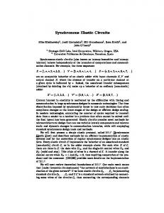
As Figure 1 shows, the locality of timing assumptions decreases, from DI systems (which incorporate no assumptions) to burst-mode circuits (in which timing assumptions involve global characteristics of system behavior, and the environment’s response is slower than the module’s delay). Our work targets NCL,8,9 which fits the QDI methodology because it imposes timing assumptions only on wire forks. However, rather than assuming isochronic forks, NCL requires the skew after the fork to be less than the circuit response time. This change makes it far easier for the design to satisfy timing constraints. However, NCL doesn’t distinguish between critical and noncritical wires, and thus designers must ensure that all wire forks meet timing assumptions. Although this change requires more work, it relieves designers from having to determine whether a fork is critical or not. In this way, the NCL design flow is more likely to produce an acceptable design, but it must check more timing assumptions than a typical QDI design flow.
Functional redundancy
■
Delay sensitive
Null convergence logic
Speed independent Quasi delay insensitive
Burst mode Synchronous
Nonlocality of timing assumptions Figure 1. Functional redundancy and the nonlocality of timing assumptions for different asynchronous design flows. The gray area indicates that NCL has more assumptions than in typical quasi-delay-insensitive circuits but that each assumption is safer.
a y b
y a b
(a)
(b)
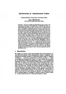
Figure 2. Illustration of acknowledgment by outputs. The transition
Delay-insensitive combinational circuits
output y properly acknowledges the same input transitions (b).
A combinational gate output reflects the gate’s Boolean function after its gate delay. Certain functions let you infer the input state by observing the output. For example, output 0 for a two-input OR gate means both inputs are 0. For the other three possible inputs, the output is 1. When transitioning from one set of inputs to another, the output can temporarily become 0 before returning to its proper value of 1. This behavior constitutes a hazard. A circuit in which hazards cannot occur under any distribution of gate and wire delays is delay insensitive. Imagine a circuit in which false transitions don’t occur and where you can always infer the inputs by merely observing the outputs. You could say that the output of such a circuit has
full acknowledgment of all its inputs. The notion of acknowledgment is key to ensuring delay insensitivity. If every transition at a wire or gate in a circuit translates its firing results into changes in the primary outputs, the circuit behavior does not depend on transition timing and is delay insensitive. Figure 2 illustrates the acknowledgment concept. In Figure 2a, the transition at y does not properly acknowledge the rising input transitions at both a and b, because y changes as soon as any one of its inputs transitions, regardless of the value at the other input. Output y properly acknowledges the same input transitions in the circuit in Figure 2b because, in this
July–August 2002
at y does not acknowledge the input transitions at a and b (a);
5
Special DAC Section
Null state and that the circuit has asserted Ack signals to 0. When Ack_b Completion Data arrives, a register’s outputs detector change from Null to Data, and the Data wave front propagates Request through a combinational circuit to Combinational Register A Register B the next register’s inputs. Simultalogic Request neously, a completion detector checks for a Data code word at its inputs, and replies by raising the Completion detector Ack signal. This signal disables the Ack_a previous register’s request line and prepares the register for storing the next Null wave front. The requestFigure 3. NCL system implementation. acknowledgement mechanism of register interaction ensures a twocase, y does not change until the circuit asserts phase discipline in NCL system functioning and prevents collisions between different Data both a and b as 1. wave fronts.10 Null convention logic Guaranteed implementation of this behavior NCL is a specific way of implementing data requires gates, such as those based on NCL, that communication based on DI encoding. Data satisfy the following properties: changes from the spacer (Null) to a proper code word (Data) in the set phase, and then back to ■ Monotonic Null → Data (Data → Null) tranNull in the reset phase. NCL targets simple DI sitions at a combinational circuit’s inputs encoding in which Data code words are one-hot result in monotonic Null → Data (Data → codes (only 1 bit of the code can be asserted to Null) transitions at its outputs. These prop1), and a vector with all entries equal to 0 reperties are achievable by using gates that resents the spacer Null. For example, in dual-rail implement a positively unate function (all encoding, two wires, a.0 and a.1, represent each inputs in an inversionless function). Each signal, a. Thus, this method encodes a = 1 as a.0 gate can then make at most one transition in = 0 and a.1 = 1, and a = 0 as a.0 = 1 and a.1 = 0. the set or reset phases, much like in DI encoding lets the receiver determine that a precharge dynamic circuits. code word has arrived by observing the code ■ For intermediate states of the Null → Data word itself, without appealing to timing assumpinput transition, a combinational circuit tions. In particular, for dual-rail signals a.0 and must keep some of its outputs in Null (so a.1, an OR gate (a.0 + a.1) is the simplest detecthat it does not produce Data prematurely). tor for validating a code word at a.0 and a.1. For intermediate states of the Data → Null At an architectural level, NCL systems clearinput transition, the circuit must keep some ly separate sequential and combinational parts, of its outputs in Data (so that it does not promuch in the same way as with synchronous sysduce Null prematurely). Thus, NCL gates tems, as Figure 3 shows. must track the current function; that is, gates must have internal memory. NCL systems borrow the idea of organizing register interaction in DI fashion from microThese conditions lead to a general reprepipeline architectures.10 The main difference concerns data path implementation: It is delay sentation of an NCL gate as g = S + gR′, where insensitive for NCL and synchronous for S and R are the unate set and reset functions. micropipelines.11 Because there’s only one designated value for To understand how the NCL system func- Null (the vector with all 0s), the system must tions, assume that all registers are initially in the uniformly reset every gate by changing its out-
6
IEEE Design & Test of Computers
put to 0 only when all inputs to that gate are 0. This refines the representation of gate g to the threshold function g(x1, x2, …, xn) = S + g (x1 + x2 + … + xn). Figure 4a shows a semistatic CMOS implementation of an NCL gate. Figures 4b and 4c show an implementation and notation for a particular NCL gate with the function g = x1x2 + g(x1 + x2), known from literature as a Muller’s C-element.
g
g x1
x1
n-tree unate function
xn
C
g
x2
x1 x2
(a)
(b)
(c)
Figure 4. Semistatic CMOS NCL gate implementation (a), a particular NCL gate known as Muller’s C-element (b), and its notation (c).
NCL design flow NCL is coded at the registertransfer level (RTL). To synthesize and simulate an NCL circuit at the RTL using commercial tools, the tools must handle the Null value and sequential behavior of threshold gates. Designers must ■
■
separate combinational logic and registers, writing combinational logic as concurrent signal assignments or in processes; and instantiate NCL registers and provide a simulation-only model for sequential behavior of NCL gates but ignore the simulation model during synthesis. For synthesis, threshold gates are represented by their set functions and look like Boolean gates.
As Figure 5 shows, the NCL design flow uses off-the-shelf simulation and synthesis components. The flow executes two synthesis steps. The first step treats NCL variables as single wires. The synthesis tool performs HDL optimizations and outputs a network built from components in the Synopsys GTech (generic technology) library, as if it were a conventional Boolean RTL circuit. The second step expands the intermediate GTech netlist into a dual-rail NCL by making dual-rail expansions and mapping them into the threshold library. The details of these two implementation steps can affect the quality of the final results. Ligthart et al. suggested a regular method for NCL implementation,8 which we call NCL_D, based on delay-insensitive minterm synthesis July–August 2002
RTL simulation
VHDL
DesignWare
RTL synthesis
Cell library
GTech netlist
DesignWare
Two-rail expansion and synthesis
Cell library
NCL netlist
Figure 5. RTL flow for NCL.
(DIMS).1 This method implements these two steps as follows: 1. It maps the optimized network into twoinput NAND, NOR, and XOR gates. 2. It first represents each wire as a dual-rail pair, a.0 and a.1, and then directly translates two-input Boolean gates into threshold gate pairs with limited optimization of a threshold network.
7
Special DAC Section
a.1 c.0
C
■
b.2 a
property verification (no sharing in the acknowledgment is allowed), and little room for optimization (optimization can easily destroy DI properties).
c b T
a.0
c.1
b.0
Figure 6. Dual-rail expansion for a NAND gate.
Figure 6 shows a step-2 implementation for two-input NAND gate c = (a, b). (In the remaining figures, a “T” inside a gate symbol indicates a threshold gate; a “C” indicates a Muller’s Celement.) Therefore, for gates and wires before forks, this translation scheme supports circuits that are delay insensitive by construction; for wires after forks, justifying correctness requires a review of timing assumptions. The main advantages of NCL_D circuits are the translation scheme’s simplicity and the automatic verification of DI properties during implementation. Unfortunately, NCL_D circuits incur significant overhead, which comes from two main sources: ■
over designing because of the locality of DI
NCL flow with explicit completeness Our design flow, NCL_X, exploits the idea of separate implementations for functionality and delay insensitivity. NCL_X partitions an NCL circuit into functional and completion parts, allowing independent optimization of each. Modifying the flow’s implementation steps permits this separate implementation and optimization. In step 1, designers perform a conventional logic synthesis (with optimization) from the RTL specification of an NCL circuit. This step also maps the resulting network into a GTech library, using gates that implement set functions of threshold gates. Step 2 involves the following substeps: ■
■
reducing the logic network to unate gates by using two different variables, a.0 and a.1, for direct and inverse values of signal a (the obtained unate network implements rail.1 of a dual-rail combinational circuit); enabling dual-rail expansion of the combinational logic by creating a corresponding dual gate in the rail.0 network for each gate in the rail.1 network; and
Ack_b
b.go
C done
C Ack_a
C
a.go
Completion detectors for register and combinational logic
C
Request Register A
Request Combinational logic
Register B
Figure 7. NCL_X produces an NCL system with explicit completion detection.
8
IEEE Design & Test of Computers
■
ensuring delay insensitivity by providing local completion detectors (OR gates) for each pair of dual gates and connecting them in a completion network (multi-input C element) with a single output, done.
Implementing the NCL_X design flow requires a minor modification of interfacing conventions within the NCL system. We assume that for each two-rail primary input (a.0, a.1), explicit signal a.go exists such that a.0 ≠ a.1 → a.go = 1 (set phase), whereas a.0 = a.1 = 0 → a.go = 0 (reset phase). Figure 7 (next page) shows the modified organization of the NCL system. Unlike the system in Figure 3, this system has separate completion detectors for combinational logic and registers. Designing the combinational logic for a 4-to2 encoder illustrates this design flow. Figure 8 gives the RTL specification for this encoder. Figure 9 (next page) shows the design steps in the NCL_X implementation of the encoder. C-element In.go provides information about the validity of input code words. This element combines all completion signals for primary inputs. Output I.go connects to C-element done. In an NCL_X implementation, the only unacknowledged transitions possible occur at wires after a fork. For these transitions, correct circuit behavior depends on the timing assumption that bounds the possible skew of wire delays after the fork for the duration of the set (reset) phase. This assumption is very conservative and easily testable. Apart from wire fork points, an NCL_X circuit is delay insensitive. A clear boundary between a circuit’s functional and completion parts significantly simplifies optimization procedures. Completion part optimization Some internal gates can receive an acknowledgment through the functional parts. In these cases, their local completion detectors are redundant, and thus removable without any influence on DI properties. Such an analysis can be automatic and help optimize the completion network. The 4-to-2 encoder example illustrates this specific type of optimization. For the functional part, gate pairs (x.0, x.1) and (y.0, y.1) cannot switch until primary inputs July–August 2002
encode : process(din) begin if din = “1000” then d