Design of Centimeter-scale Inchworm Robots with Bidirectional Claws Dongwoo Lee, Sinbae Kim, Yong-Lae Park, and Robert J. Wood
Abstract—We present the design and fabrication of centimeter scale robots, which use inchworm-like motion and bidirectional claws. Two prototypes for different locomotion goals were built utilizing these two characteristics: Type I is designed particularly for horizontal surfaces utilizing two linear actuators and compliant claws. This robot is capable of steering and straight motion by utilizing directionally anisotropic friction. Type II is a variant of Type I that is designed for locomotion on ferromagnetic ceilings or vertical planes by using permanent magnets. The Smart Composite Microstructures (SCM) technique enables versatile and multi-jointed meso-scale devices suitable for such robots.
I. INTRODUCTION
T
animal locomotion has many forms including legged locomotion and inchworm-like locomotion, the latter involving repeated extension and retraction to move forward. In the case of legged locomotion, it is known that elasticity allows the biological system to enhance energy efficiency, since strain energy is stored when the leg contacts the ground and is released at the start of the swing phase [1][2]. Application of this energy efficient mechanism to a robotic system could require a large number of actuators or a potentially complicated body structure [3][4][5]. Since it is difficult to achieve such a mechanism in small scale robots, worm-like mechanisms have been studied for centimeter-scale robots [6][7][8]. In both legged and worm-like systems, bidirectional adhesion properties can be remarkably beneficial. For instance, Gecko lizards can climb up various kinds of surfaces utilizing dramatic difference in normal and shear adhesion which is achieved by hierarchical and directional adhesion foot pads [9]. Gastropods use the difference in reactive forces and frictional forces generated by the wave of their muscular structure of their feet [10]. Also, slanted spines or claws of insects prevent the animal from slipping backwards, while the appendages reduce the resistance while moving on rough surfaces [11]. Such bidirectional differences provide solutions to achieve difficult locomotion tasks such as climbing and crawling on rough surfaces without complex control. Roboticists have drawn inspirations from this concept to design their robots. There are several successful examples that employed such directional properties ERRESTRIAL
D. Lee and S. Kim are with the School of Engineering and Sciences, Harvard University, Cambridge, MA 02138, USA.
[email protected],
[email protected]) Y.-L. Park is with the Wyss Institute for Biologically Engineering, Harvard University, Boston, MA 02115, USA.
[email protected]) R. J. Wood is with Faculty of the School of Engineering and Sciences, Harvard University, Cambridge, MA 02138, USA.
[email protected])
Applied (e-mail: Inspired (e-mail: Applied (e-mail:
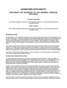
Fig. 1. Robots with bidirectional claws and worm-like mechanism: (left) Type I is on a paper substrate with a penny and (right) Type II is on a ferromagnetic vertical plane. (switch panel)
[12][13][14]. In this paper, the combination of worm-like motion and bidirectional footpads was adapted to develop centimeter size robots. Even though mechanisms that use inchworm-like motion and bidirectional claws have been applied to several small robots previously, they had some limitations in achieving a variety of locomotion tasks. We propose two different prototypes that overcome these challenges. The Smart Composite Microstructures (SCM) process enables such small but multi-jointed structures [15]. Type I is designed particularly for horizontal planar locomotion (fig. 1. (left)). In this robot, inchworm-like motion is achieved using piezoelectric linear motors (Squiggle motor® ) and a custom built elastomer spring. Compliant claws enhance the bidirectional friction characteristic since the angle of the claws can be passively changed resulting in high frictional anisotropy for forward and backward directions. This is also a mechanism to increase conformation to the substrate. Type I is capable of steering and traveling on horizontal planes as well as moderately inclined surfaces. This robot measures 18.5 mm (minimum) in length and 1.4 g in weight. Type II is designed for locomotion on ferromagnetic planes in any orientation (fig. 1. (right)). In this robot, extending-retracting motion is accomplished with a Squiggle motor® and four permanent magnets that also allow the robot to stick to the ferromagnetic surfaces. This prototype is capable of traveling on ferromagnetic vertical planes and ceilings. Type II is 16.0 mm (minimum) in length and weights 1.7 g.
The Froude number is used to determine the dominant energy of the system and can be calculated as (3), assuming that there is no slippage for the backward direction [16]. Fr
Fig. 2. Schematic of the simplified body structure and locomotion strategies for (a)-(c) (lateral view) moving forward and (d)-(e) (dorsal view) steering.
v2 f g
(3)
Froude numbers of most inchworm-like mechanisms are much less than one, and our robot conforms to this standard (approximately 3 104 in our case). This implies that the dominant energy consumption for locomotion is due to friction rather than inertia of the system. Therefore, decreasing the frictional force for the forward direction may decrease the energy consumption as described in (1). One candidate method to decrease f would be minimizing
II. MECHANICAL DESIGN OF TYPE I A. Locomotion Strategy Fig. 2 shows the schematic of the simplified body structure and locomotion strategies for Type I. In this illustration, f , and b indicate the effective dynamic friction coefficients for the sliding stance and anchoring stance, respectively, m is the mass of half of the body,
is the angle between the
substrate and the spine, and f and
b
represent travel
lengths of a pad per stroke for forward and backward directions, respectively. In the following sections,
s
and
a
will be called sliding angle and anchoring angle that are
defined as for sliding stance and for anchoring stance, respectively. As shown in fig. 2, the robot can achieve straight motion using the following steps. First, the actuators extend (a) and the higher friction in the backward direction makes the sliding distance of the front pad to the forward direction much longer than that of the rear pad to the backward direction. When the actuators contract (b, c), the bidirectional property of the pad brings the rear pad forward, while the front pad stays at the same position, causing the robot to move in forward direction. The iteration of (a) – (c) steps leads to the locomotion of the robot. Steering motion can be achieved by differentiating the displacement of the two linear actuators, as shown in fig. 2 (d) – (f). For efficient locomotion, figuring out the relationship
s .
Dai, et al., has shown this relationship and developed a mathematical model by measuring the angle between the claw of a beetle (Coleoptera, Scarabaeidae) and a substrate, as well as the frictional force [17]. We have adapted a similar model to find out appropriate values of
s , and a .
As shown in fig. 3, the irregularity of the ground surface was modeled as a half sphere. In this figure, r is the radius of the spine tip, R is the radius of the half sphere, W is the weight exerted on the ground, F is the actuation force, N is the normal force to the surface of the spine, is the dynamic frictional coefficient between the spine material and the ground material, and is the angle between the ground surface and the line which connects the centers of the tip and the half sphere. Equation (4) and (5) show the non-slip condition for the anchoring step and slip condition for the sliding step, respectively.
between and the energy required for locomotion is necessary. The energy to overcome friction and the kinetic energy of the system are described in (1) and (2), respectively. E f ( f f b b )mg
Ek
1 (2m)v 2 2
(1) (2)
Fig. 3. Free body diagram of the spine and the substrate for the anchoring (a) and the sliding stance (b).
F cos sin , 0 W sin cos 2
(4)
F sins coss , 0 s W coss sins 2
(5)
Equation (4) implies that the possibility of slipping for the anchoring stance will diminish as the radius of the tip is decreases since the value of declines. In addition, with (5), it is possible to determine the relationship between the sliding angle and the friction for the forward direction. Fig. 4. shows the effective dynamic friction coefficient ( f ) based on (5). In this figure, decreasing the sliding angle significantly reduces frictional force that the robot needs to overcome for the forward motion. For example, decreasing the sliding angle from 52 degrees to 34 degrees when is 0.2 results in
Fig. 4. The relationship between
f
and
s
a 50% reduction in the effective friction. If f decreases 50 %, the robot can save 50 % of the required energy as can be seen in (1). Thus, the sliding angle should be minimized and the anchoring angle should be set approximately 45 degrees, which causes the claws to engage as many asperities as possible [18]. B. Body Design & Fabrication The body of Type I consists of two linear actuators, an elastomer spring, two directional foot pads with two compliant spines for each, and six hinges resulting in a front pad with three degrees of freedom with respect to the rear pad, as shown in fig. 5 (b) and (c). The overall body structure, except the actuators and the motor holder, were fabricated using the SCM process [15], which enables a lightweight multi-jointed flexure-based structure. The robot’s weight is 1.4 g (two squiggle motors weight 0.5 g) and length is 18.6 mm when retracted and 20.0 mm when stretched. Two Squiggle motors® (SQL-RV-1.8, New Scale Technologies, Inc.) were rigidly attached to the rear pad. Because the actuator is very susceptible to tangential forces
[19], the force to the screw of the actuators should be in line with the shaft centerline as much as possible. Also, the actuator can exert up to 50 grams of force each according to the manufacturer specifications, which must be enough for overcoming both the static frictional force for the front pad for the front direction and the restoring force from the elastomer spring. Since the mass of the two actuators is much heavier than that of the body frame, and the actuators are rigidly bonded to the rear pad, a counter balancing mass with the same weight of the actuators was placed on the front pad. The elastomer spring is a crucial component of the robot. Its restoring force causes the rear pad to overcome friction in the forward direction and brings the two pads closer together. The stiffness of the spring can be calculated simply as ke Ae Ee / Le assuming that it has a rectangular shape with cross-sectional area Ae , Young’s modulus Ee , and initial length Le . This component was fabricated with a molding process where the mold was fabricated with a 3D printer (Objet, Connex 500™), and Ecoflex30® (Smooth-On, Inc.) was thermally cured in the mold.
Fig. 5. Anatomy of Type 1: (a) lateral view of the compliant spine, and (b), (c) dorsal view of the robot body. Red arrows indicate the forces exerted on the corresponding parts. The red scale bar in (c) is 12 mm.
Fig. 6. Anatomy of Type 2: (a) lateral view of the robot and (b) dorsal view of the robot. Red arrows indicate the forces on the parts and yellow squares are the magnets. The poles are shown near the magnets. The red scale bar in (b) is 10 mm.
The compliant claws underneath the footpad allow the system to have a small sliding angle compared to the anchoring angle. Due to the compliance of the flexure, is changed under varying frictional forces for different stances. As in fig. 5 (a), at the sliding stance, friction exerted towards the back direction causes s to decrease, allowing the robot to experience less frictional force. At the anchoring stance, however, the force in the forward direction causes the spine to rotate clockwise until the stopper fixes the angle a approximately 45°. The angular stiffness of the flexure in the claw structure can be calculated by K f E f I f / L f , where E f is the Young’s modulus of the flexure, I f is the moment
of inertia of its cross-section, and L f
is the length of the
flexure. Even though a very compliant flexure would seem to be useful due to its ability to decrease the sliding angle significantly, it would not be possible to engage the asperities on the substrate during the subsequent anchoring stance.
In these equations, Fs is the attractive force between a ferromagnetic surface and a 2x2 magnet array, and Fm _ ext , Fm _ ret are the forces between front and rear pad, which is
created by the magnets when the body is fully extended and retracted, respectively. Also, Fa is the force exerted by the actuator, Fsf is the static frictional force of a pad for the forward direction, mr is the mass of the whole body, and g is the gravitational acceleration. The total force acting on a magnetized object ( F o ) that experiences uniform magnetization M can be obtained with (7), where Vo is the volume of the object and B is the magnetic flux density [20].
Fo Vo (M )B
(7)
III. MECHNICAL DESIGN OF TYPE II A. Locomotion Strategy As shown in fig. 6, Type II uses the attractive force of permanent magnets for the retracting motion. When the robot is on a ferromagnetic surface, the magnets have two main roles: generating the attractive force on ferromagnetic surfaces to make the robot adhere to the surface and causing the rear pad to move forward during retracting motion. One more condition for the successful locomotion of Type II is that the actuator should overcome both the static friction of the front pad and the pulling force by the magnets at the contracted state. Those conditions for locomotion on a ferromagnetic ceiling can be described by (6). Parameters of Type II determined by (6) can be used for climbing locomotion as well assuming that friction coefficient for backward direction is large enough and the mass of a pad is small enough compared to Fm _ ext and Fa Fs mr g
(6-1)
Fm _ ext Fsf
(6-3)
Fa Fm _ ret Fsf
(6-2)
Fig. 7. FEA analysis: (a) cubic magnets and a ferromagnetic substrate were modeled in air. Parameters which determine the configuration of the system were determined to satisfy successful locomotion. (b) stream line plot for magnetic flux density. The legend indicates the values in Tesla.
B. Body Design Contrary to Type I, Type II employs Sarrus linkages that allow the rear pad to have only one degree of freedom relative to the front pad, and it uses only one actuator as shown in fig. 6. The main body of Type II is made with SCM as in Type I. The robot’s maximum and minimum lengths, when fully extended and retracted, respectively, are 16.0 mm and 18.5 mm, and the weight is 1.7 g. Finite Element Analysis (FEA) based on COMSOL Multiphysics® was conducted to calculate the magnetic force on the robot. Applying FEA to find the magnetic attractive force is beneficial since it can easily calculate the magnetic flux density over the surfaces of the geometry once enough space is defined for the air, as shown in fig. 7 (b). In the simulation, we assumed 75,000 A/m for magnetization of the magnets, 5,000 for the relative permeability of iron. The value of magnetization creates a magnetic flux density of about 0.4 T at the surface of the 3.175 mm cubic magnet. As depicted in fig. 7, we set the parameters d x _ ret ( d x when retracted), d x _ ext ( d x when extended), d y , and d z to define the configuration of the 2x2 magnet array and the ferromagnetic substrate. By changing the parameters, we were able to find the values that satisfy the condition illustrated in (6). The FEA result and the determined parameters for the robot are described in the Table I. Those parameters were tuned and employed in the prototype. More details are illustrated in Section IV. TABLE I PARAMETERS DETERMINED AND RESULTING FORCES FROM FEA
Parameter
Value
Unit
d x _ ret
4.8
mm
d x _ ext
9.7
mm
dy
3.8
mm
dz
6
mm
Fs
0.057
N
Fm _ ret
0.31
N
Fm _ ext
0.094
N
IV. RESULTS A. Performance of the Compliant Claws in Type I We investigated the performance of the compliant claws in Type I comparing with that of rigid claws. In this experiment, we measured the dynamic frictional forces for forward and backward directions with both compliant and rigid spines. In the experiments, we placed the robot on a horizontal flat surface and hung a weight by connecting with an inextensible but flexible string through a pulley, as shown in fig. 8 (a). Then, by increasing the weight, we measured the minimum mass to keep the robot sliding. We pushed the robot slightly at
Fig. 8. Experiment for measuring the dynamic friction coefficient: (a) schematic diagram of experimental set-up. (b) magnified video capture showing sliding angles for (upper) fixed claws and for (below) compliant claws. (c) Dynamic friction coefficient vs. sliding angle.
first to make it overcome the static friction and experience dynamic friction. For the rigid claw experiments, we used the same robot body but the compliant claws are fixed to the pad with epoxy. The angles s and a were 40.3 degrees in this case. The experiments were performed on various everyday object surfaces such as sand paper, standard printer paper, an aluminum plate, and fabric. During the experiment, we recorded the motion of the robot and found the sliding angle with snapshots of video as shown in fig. 8 (b). With the measured values, it was possible to determine the relationship between f and s , as shown in fig. 8 (c). Here, red indicates the result from the compliant claw, while blue is for the rigid claw. The result from the model in section II were also drawn in fig. 8 (c) when is 0.1, 0.2 and 0.3. Even though the dynamic friction f seems to be smaller than expected, the general pattern follows the model shown in the Section II. For sand paper and fabric, the model with 0.1 0.3 range fits the experimental data. This is because the substrates have irregularities large enough to be modeled as half spheres. We also performed tests for the backward direction to see if there is any slippage. In the experiments, we could not move the robot body without damaging the robot on rough or soft surfaces (sand paper, paper, and fabric), but on smooth and hard surfaces (aluminum plates), the pulling forces for both compliant and rigid cases were the same. Considering that the backward friction for both compliant and rigid cases is the same, compliant pads displayed better performance. Because the robot with compliant pads has lower f for the forward direction, it is beneficial for efficient locomotion since the energy consumption is
expected to be proportional to the friction coefficient, as aforementioned. B. Locomotion of Type I Type I was able to turn with a simple control strategy. As seen in Fig. 9 (a), steering motion was achieved by simply actuating only one of the motors. The achievable radius of curvature on a paper substrate was 35 mm. Also, 90 degree turns can be realized with 10 iterations of inchworm-like motion. Type I was also capable of climbing on inclined planes. Fig. 9 (b) shows the climbing robot on a 33 degree tilted fabric plane. For slopes higher than 33 degrees, the contact force is decreased between the front claws and the substrate resulting in failure to create enough frictional force for the front pad to haul the back pad. As can be seen in Fig. 9 (c), straight motion can be achieved by actuating two motors simultaneously. In our experiments, we operated the controller open-loop at the maximum operating frequency of 1Hz, which is limited by the system dynamics. Each snapshot in the figure shows the locations of the robot after five iterations of inchworm-like motion. The highest speed that Type I achieved was 3 mm/s. For the straight motion, the robot can carry an additional payload of 0.7 g. This can be improved with higher stiffness of the flexible claws.
Fig. 9. Video snapshots for (a) steering motion on paper, (b) climbing motion on a 33 degree tilted fabric surface, and (c) straight motion on paper of Type I. The locations of the robot after a few steps are drawn and the numbers of steps are shown in the figures.
C. Locomotion of Type II Parameters determined with FEA were tuned to achieve locomotion in both ferromagnetic vertical planes and ceilings. In the experiment, the parameters d x _ ret , d x _ ext , d y , and d z were set as 4.2 mm, 9.4 mm, 3.4 mm, and 2.8 mm respectively. Measurements show that the parameters create the attractive magnetic forces, Fs as 0.023 N, Fm _ ret as 0.19 N, and Fm _ ext as 0.043N. There are a few reasons that the FEA results predict the higher values than the measured values: the magnetization became weak as time went by, and the relative permeability of the plane on which we tested was smaller than that of pure iron. Even though there were some discrepancies between the experimental and the FEA results, the tuned parameter values satisfied the locomotion conditions described in the Sec. III A. Type II was able to travel on the ferromagnetic vertical planes and ceilings, as shown in fig. 10 (a) and (b). The locations the robot reached are shown along with the number of iterations of inchworm-like motion that the robot utilized. In addition, the maximum additional payload it could carry was 1.2 g while climbing. To our knowledge, Type II is one of the smallest climbing robots to date although future work can further miniaturize the mechanics and also must address on-board power and control. V. DISCUSSION & FUTURE WORK We demonstrated that the combination of inchworm-like motion and the bidirectional anisotropy of the footpads
Fig. 10. Locomotion on a ferromagnetic (a) vertical wall and (b) ceiling. The numbers of steps are shown at the location that the robot achieved.
Robot
Type I HAMR² [21] RoACH [22] Si μ-Robot [23]
TABLE II A COMPARISON OF MICRO CRAWLING ROBOTS Speed (body Length(mm)/ On-board Steering lengths Weight(g) Power /sec)
TABLE III A COMPARISON OF CRIMBING ROBOTS Actuator
0.16
18.5/1.4
Yes
No
Squiggle Motor®
4
57/2
No
No
PZT
1
30/2.4
Yes
Yes
SMA
No
Thermal (Polyimi de)
0.4
15/0.083
No
enable a variety of locomotion tasks at small scales. There are some modifications that we can make to improve the performance of our current design. First, a material with low relative permeability can be used for the screw of the actuator. This will allow Type II to be equipped with two actuators to achieve steering motion on the ferromagnetic surfaces, since the iron screw in the current design can make the robot unstable when the pads have more than one degree of freedom. Also, for Type I, a tail design can be added to increase the contact force between the claw and the substrate. Then, the robot can climb on steeper slopes [27]. Since Type I and Type II are relatively small compared with previously demonstrated crawling and climbing robots and can operate on a variety of surfaces (Table II and Table III), it is expected that future versions of those robots can be useful for a variety of applications inappropriate for larger robots. For practical applications, power autonomy is required: Future work will focus on on-board power and control circuitry and also explore different actuator types. We are also developing different types of bidirectional pads for non-ferromagnetic vertical surfaces, as shown in fig. 11. This consists of claws and elastomer springs that have low stiffness in the normal direction (z-direction in fig. 11) and
Length(mm) /Weight(g)
Surface
Onboard Power
Mechanism
Type II
16/1.7
Ferromagnetic
No
Spine, Magnet
580/400
Rough
Yes
Spine
600/370
Smooth
Yes
130/70
Smooth
Yes
NA/1460
Ferromagnetic
No
Magnet
500/1500
Smooth
No
Vacuum
Spinybot [12] Stickybot [13] Waalbot [24] Magnetic WCR [25] SURFY [26]
Dry Adhesive Dry Adhesive
moderate stiffness in the plane (x-direction in fig. 11). This is required to make the spines adapt to rough surfaces and sustain the weight of the robot [12]. The elastomer structure was fabricated with the same molding process. ACKNOWLEDGMENT The authors appreciate Rebecca Kramer, Hyun-Sung Park, Dr. Jamie Paik and Dr. Hiroto Tanaka providing valuable comments on this work. REFERENCES [1] [2]
[3]
[4]
[5]
[6]
[7]
[8]
[9] [10]
[11]
[12] Fig. 11. Possible pad design for non-ferromagnetic surfaces. (a) The elastomer portion was fabricated with a replica molding process. (b) The compliant anisotropic pad is compliant in the normal direction and moderate in plane stiffness. The scale bar in (b) is 2mm.
Robot
[13]
R. M. Alexander, “Elastic Energy Stores in Running Vertebrates”, Amer. Zool., vol. 24 (1), pp. 85 – 94, 1984. P. Holmes, R. J. Full, D. Koditschek, and J. Guckenheimer, "Dynamics of legged locomotion: Models, analyses, and challenges", SIREV., vol. 48 (2), 207-304, 2006. S. Kim, J. E. Clark, and M. R. Cutkosky, “isprawl: Design and tuning for high-speed autonomous open-loop running,” Int. J. Rob. Res., vol. 25, no. 9, pp. 903–912, 2006. U. Saranli, M. Buehler, and D. E. Koditschek, “Rhex: A simple and highly mobile hexapod robot,” Int. J. Rob. Res., vol. 20, no. 7, pp. 616 – 631, 2001. P. Birkmeyer, K. Peterson, and R. S. Fearing, "DASH: A Dynamic 16g Hexapedal Robot", in IEEE Int. Conf. on Intelligent Robots and Systems, St. Louis, MO, 2009. B. Kim, M. Lee, Y. Lee, Y. Kim, and G. Lee, “An earthworm-like robot using shape memory alloy actuator”, Sensors and Actuators A, vol. 125, pp. 429 – 437, 2006. J. Lim, H. Park, J. An, Y. Hong, B. Kim, and B. Yi, “One pneumatic line based inchworm-like micro robot for half-inch pipe inspection”, Mechatronics, vol. 18, pp. 315 – 322, 2008. J. Koh, K. Cho, “Omegabot : Biomimetic Inchworm Robot Using SMA Coil Actuator and Smart Composite Microstructures (SCM)”, in IEEE Int. Conf. on Robotics and Biomimetics, Guilin, China, 2009. K. Autumn and A. M. Peattie, “Mechanisms of adhesion in Geckos”, Integr. Comp. Biol., vol. 42, pp. 1081–1090, 2002. M. W. Denny, “A quantitative model for the adhesive locomotion of the terrestrial slug, ARIOLIMAX COLMBIANUS”, J. Exp. Biol., vol. 91, pp. 195 – 217, 1981. N. E. Stork, “Experimental analysis of adhesion of CHRYSOLINA POLITA (SHRYSOMELIDAE: COLEOPTERA) on a variety of surfaces”, J. Exp. Biol., vol. 88, pp. 91 – 107, 1980. S. Kim, A.T. Asbeck, M.R. Cutkosky, and W.R. Provancher, “Spinybot II: Climbing Hard Walls with Compliant Microspines,” in IEEE Int. Conf. on Advanced Robotics, Seattle, WA, 2005. S. Kim, M. Spenko, S. Trujillo, B. Heyneman, V. Mattoli, M. R. Cutkosky, "Whole body adhesion: hierarchical, directional and
[14]
[15]
[16] [17]
[18]
[19] [20]
[21]
[22]
[23]
[24]
[25] [26]
[27]
distributed control of adhesive forces for a climbing robot", in IEEE Int. Conf. on Robotics and Automation, Rome, Italy, 2007. M. J. Spenko, G. C. Haynes, J. A. Saunders, M. R. Cutkosky, A. A. Rizzi, R. J. Full, and D. E. Koditschek, "Biologically inspired climbing with a hexapedal robot", J. Field Robot., vol. 25, pp. 223-242, 2008. R. J. Wood, S. Avadhanula, R. Sahai, E. Steltz, R. S. Fearing, “Microrobot Design Using Fiber Reinforced Composites”. J. Mech. Des. Vol. 130, 2008. R. M. Alexander, Principles of Animal Locomotion. Princeton University Press, 2002, ch. 6. Z Dai, S. N. Gorb, and U. Schwarz, “Roughness-dependent friction force of the tarsal claw system in the beetle Pachnoda marginata (Coleoptera, Scarabaeidae)”, J. Exp. Biol., vol. 205 , pp. 2479–2488, 2002. A. Asbeck, S. Kim, M. Cutkosky, W. Provancher and M. Lanzetta, “Scaling hard vertical surfaces with compliant microspinearrays”, Int. J. Rob. Res., Vol. 25, no. 12, pp. 1165-1179, 2006. Available : http://www.newscaletech.com/motorsforoem.html S. Floyd, C. Pawashe, and M. Sitti, ''Microparticle Manipulation using Multiple Untethered Magnetic Micro-Robots on an Electrostatic Surface,'' in IEEE/RSJ Int. Conf. on Intelligent Robots and Systems, St. Louis, MO, 2009. A. T. Baisch, P. S. Sreetharan, and R. J. Wood, "Biologically-Inspired Locomotion of a 2g Hexapod Robot", in IEEE/RSJ Int. Conf. on Intelligent Robots and Systems, Taipei, Taiwan, 2010. A. Hoover, E. Steltz, and R. Fearing, “RoACH: An autonomous 2.4 g crawling hexapod robot,” in IEEE/RSJ Int. Conf. on Intelligent Robots and Systems, Nice, France, 2008. T. Ebefors, J. U. Mattsson, E. Kalvesten, and G. Stemme, “A walking silicon micro-robot”, in IEEE Int. Conf. on Solid-State Sensors and Actuators, 1999. M. Murphy and M. Sitti, "Waalbot: An Agile Small-Scale Wall Climbing Robot Utilizing Dry Elastomer Adhesives", IEEE/ASME Transactions on Mechatronics, vol.12, no. 3, 2007. Z.L. Xu and P.S. Ma. “A wall-climbing robot for labelling scale of oil tank’s volume”, Robotica, vol. 20, pp.209–212, 2002 . G. L. Rosa, M. Messina, G. Muscato, and R. Sinatra, “A low-cost lightweight climbing robot for the inspection of vertical surfaces”, Mechatronics, vol. 12, pp. 71-96, 2002. A. Jusufi, D. I. Goldman, S. Revzen, and R. J. Full, “Active tails enhance arboreal acrobatics in geckos”, PNAS, vol. 105, pp. 4215–4219, 2008.