TELKOMNIKA Indonesian Journal of Electrical Engineering Vol.12, No.7, July 2014, pp. 5350 ~ 5361 DOI: 10.11591/telkomnika.v12i7.5778
5350
Design of Decentralized Controller for Interactive Processes through Relative Frequency Array R. Hanuma Naik*1, D.V. Ashok Kumar2, K.S.R. Anjaneyulu3
*1RGM College of Engineering &Technology, Nandyal, AP, India Syamaladevi Institute of Technology for women, Nandyal, AP, India 3 Jawaharlal Nehru Technological University Anantapur, Anantapuram, AP, India *Corresponding author, e-mail:
[email protected] 2
Abstract Tuning of controllers for multivariable process is a difficult task because of interaction involved among the variables. In this paper, a simple tuning strategy is used for design of a multi-loop PI controller to achieve desired frequency response for interactive multivariable processes. To handle the loop interaction, a pairing of controlled variable and manipulted variable is determined based on the integrity obtained from effective relative gain (ERG) and Niederlinski’s Index (NI).Then the Equivalent transfer function of model is approximated by the use of relative frequency array (RFA), Relative Gain Array (RGA). Finally a Decentralized PI controller is designed for suggested pair of variables to achieve desired gain, phase margins. The performance is verified on the industrial multivariable processe models to show the effectiveness of the proposed method. The results clearly reveal that, it gives better performance for set point changes and disturbance rejection. Simulation results are included to validate the robustness of the presented algorithm. Keywords: nteractive process, effective relative gain array (ERGA), relative frequency array (RFA), Niederlinski’s Index, polymerization reactor, independent controller. Copyright © 2014 Institute of Advanced Engineering and Science. All rights reserved.
1. Introduction The objective of the control engineer is tuning of controller parameters. Many of the industrial processes are consisting of multi-input and multi-output (MIMO) processes. Tracking of desired performance for these kinds of processes is very complicated compared with single input/output processes because of interactions existing among the variables [1]. In the literature, the Multi-loop PI/PID control using multiple single input single output (SISO) PI/PID controllers is commonly used for controlling MIMO processes with interaction [25]. The reason for using SISO PI/PID controller for Multi-loop control is its simple structure, easy tuning and ability to achieve most of the expected control objectives. It is the common scenario to extend the controller design methods of SISO systems to multi-loop systems, but it affects the performance and stability of the systems [6, 7]. Many methods [8-11] have been proposed over the period, considering loop interactions into account in the multi-loop control design. But each method has its own merits and demerits [12]. These methods considers the interactions in sequential, require minimum process information, but tuning sequence has to be repeated for correct sequence if the design sequence is not proper [13]. In independent design methods SISO controllers are designed independently by using the defined boundaries to guarantee stability and performance [14-18]. But the detailed information about the controller dynamics in other loops is not considered, the resulting performance may be poor. In this, an independent PI controller is designed for specific gain and phase margins. The interaction among the variables are determined using relative gain array (RGA) and effective relative gain array (ERGA).Then the decentralized controller is designed for the pairs of manipulated variable (input) and controlled variable (output) suggested by ERGA to achieve the desired performance of the interactive process. To determine the optimum settings of Multivariable PI controller, a consistent method is used, the closed loop performance obtained in this method is compared with existing methods and results are discussed.
Received February 12, 2014; Revised March 24, 2014; Accepted April 10, 2014
ISSN: 2302-4046
TELKOMNIKA
5351
2. Notation The notation used throughout the paper is stated below. Indexes: G c ( s ) Controller transfer function in s- domain
G p (s )
Process transfer function in s-domain
E
Relative gain array Effective energy transmission ratio array Effective relative gain array(ERGA) Gain margin
Am m
Phase margin
Kc
Proportional controller gain
Ti Ki
Integral time constant Integral controller gain
td
Time constant Time delay in seconds
N(G)
Niederlinski’s index Hadmard product Critical frequency
c e Λ e ij
g (s) ij
Deviation between output and desired input Array of critical frequency effective energy transmission ratio between output variable and input variable when all other loops are closed Transfer function of output j to input i in s-domain
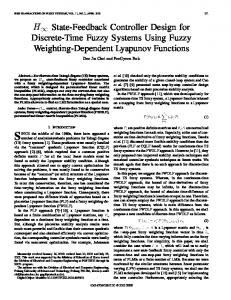
3. Problem Formulation 3.1. Interactive Processes MIMO control problems are inherently more complex than SISO control problems because process interaction occurs between controlled variables and manipulated variables. In general a change in manipulated variable, say u1, will affect all of the controlled variables y1, y2, y3… yn. Because of the interactions, the selection of the best pairing of controlled and manipulated variable for multi-loop control scheme can be a difficult task. In particular, for a control problem with n controlled variables and n manipulated variable, there are n! possible multi-loop control configurations. A schematic representation of SISO and MIMO control conFigureuration shown in Figure 1. For convenience, it is assumed that the number of manipulated variables is equal to the number of controlled variables. This allows pairing of single controlled variable and a single manipulated variable through a feedback controller. For pairing of variables, two methods are used namely RGA and ERGA. These two are discussed in section 4.
Figure 1. Single-Input and Single Output (SISO) Process
Design of Decentralized Controller for Interactive Processes through… (R. Hanuma Naik)
5352
ISSN: 2302-4046
Figure 2. Closed Loop Interactive Multivariable Process Consider the closed loop stable interactive multivariable system as shown in Figure 1. Generalized transfer function matrix of the process is:
g p11 (s) g p12 (s) ... g p1n (s) g p21 (s) g p22 (s) ... g p2n (s) G p (s) = ... ... ... ... g (s) g pn2 (s) ... g pnn (s) pn1
(1)
Where the process G (s) is first order process with delay time (FOPDT), i.e. pij g p ij (s ) =
K Ts + 1
e
-τ s d
(2)
And the structure of full dimensional controller is of the form,
g c11 (s) g c12 (s) ... g c1n (s) g (s) g (s) ... g (s) c22 c2n G c (s) = c21 ... ... ... ... g (s) g (s) ... g cnn (s) cn1 cn2
(3)
Where the controller is of the form: 1 g c , ji (s ) = K p , ji + + K d , ji s K i, ji s
(4)
The controller output and plant output are given by: u i = G c ei and y i = G p u i
(5)
Where, u i (i = 1, 2, 3, .....n), yi (i = 1, 2, 3, ....n) and ei = yspi - yi are inputs of the plant, output of the plant and error signal to the controller respectively. In practical, when MIMO control loop is closed, there exist interactions among the loops as a result of existence of non-zero diagonal elements in the process transfer function matrix.
4. Interaction Analysis 4.1. Relative Gain Array (RGA) Interaction analysis is most widely used technique in control system conFigureuration for multivariable processes. The most commonly used method for interaction measurement is
TELKOMNIKA Vol. 12, No. 7, July 2014: 5350 – 5361
ISSN: 2302-4046
TELKOMNIKA
5353
RGA. Based on interaction matrix obtained with RGA, the pairing of manipulated variable and controlled variable is formed. The RGA is defined as follows: Let K=G (0) be the matrix of steady state gains of the transfer function matrix G p (s) . (6)
lim G (s ) = [K ] s 0 p
Further let R be the transpose of inverse matrix K. R = [K
-1 T -T ] = [G (0) ]
Therefore, RGA for n n systems is, λ11 λ -T λ = G(0) G (0) = 21 λ 31 λ n1
λ12
...
λ 22
...
λ 32
...
λ n2
...
λ1n
λ 2n
(7)
λ 3n
λ nn
Thus from the Equation (7) it is possible to describe the level of interaction, large value of λ ij means that there is strong interaction between corresponding inputs i and output j. If the value of λ is greater than 0.5 and approaches towards unity, the interaction also leads between ij
corresponding pairs. In general λ 1 is the ideal case for pairing and avoiding negative ij pairing. The RGA is depend upon steady state gains and most suitable for nonlinear plants operating around steady state point. The negative diagonal in the RGA matrix gives sufficient condition for instability. The pairing which leads the instability is avoided by using Niederlinski’s theorem. The Niederlinski’s index (NI) for the control structure s above is denoted by N (G) and defined as: N (G ) =
G (0 ) π g ij
i, j = 1 , 2 , 3 , .....n
(8)
Where G(0) denotes determinant matrix G(0) and πg ij denotes product of diagonal elements of G(0) for a fully centralized control system. For a stability of complex nonlinear system, NI should be greater than zero. For dynamical interaction study, the effective relative gain array (ERGA) is used. 4.2. Effective RGA The energy transmission ratio of gij (s) is expressed as: e ij g ij (0 )ω c ,ij
Where, ω
c,ij
i, j = 1 , 2 , ........n
is the critical frequency of the transfer function. For the over all system, the energy
transmission ratio can be expressed by effective energy transmission ratio array and given by:
e1 1 e E = 21 . .. e n1
e1 2 e22
. ..
...
. ..
en2
. ..
. ..
= G (0 ) Ω . .. e n n
e1 n e2n
(9)
Design of Decentralized Controller for Interactive Processes through… (R. Hanuma Naik)
5354
ISSN: 2302-4046
Where,
g1 1 (0 ) g (0 ) G (0 ) = 2 1 . . . g n 1 (0 )
g1 2 (0 )
...
g 2 2 (0 ) ... g n 2 (0 )
...
g1 n (0 )
g 2 n (0 ) ... g n n ( 0 )
... ...
And,
ω c11 ω Ω = c21 ... ω cn1
ω c12
...
ω c1n
ω c22
...
ω c2n
...
...
...
ω cn2
...
ω c n n
Are the steady state gain array and the critical frequency array respectively. The effective relative gain array can be defined as: e
Φ ij =
(10)
ij Λ e ij
Where, e Λ is the effective energy transmission ratio between output variable and input variable ij
when all other loops are closed. Over all ERGA (Φ) can be calculated as: Φ = EE
-T
(11)
The ERGA based loop pairing rules requires that manipulated and controlled variables in the main loop be paired by those pairs whose ERGA and NI values are positive and closest to 1.0. The relative frequency array can be written as: RFA =
-T
(12)
5. Determine Equivalent Transfer Function for Integrity To reveal the model relations between when all loops are open and all loops are closed, we first define the relative critical frequency, γ ij as the ratio of loop yi-ui critical frequencies between when all other loops and when other loops are closed. γ ij
ω c,ij ωˆ c,ij
Where ωˆ c,ij is the critical frequency of loop i-j when other loops are closed. We obtain the formula for calculating: γij =
ij λij
(13)
When the relative critical frequencies are calculated for all the input-output pair of a multivariable process, it results in an array of the form, i.e, relative critical frequency array (RCFA) defined as:
TELKOMNIKA Vol. 12, No. 7, July 2014: 5350 – 5361
ISSN: 2302-4046
TELKOMNIKA γ11 γ Γ = 21 ... γ n1
γ12
...
γ 22
...
...
...
γ n2
...
5355
γ1n γ 2 n ... γ nn
And elements can be determined by:
Γ = Λ
(14)
By assigning the equivalent transfer function (ETF) when other loops are closed to have the same structures as the open loop transfer function, we can approximate ETFs in terms of relative gains and relative critical frequencies when the control system is closed as: ˆ
-θ s gˆ ij (s) = gˆ ij (0)g ij0 (s)e ij
Where
θˆ ij
(15)
is the time delay of ETF.
The ETF when other loops closed becomes:
gˆ ij (s) =
gij (0) λij
gij (0)e
- ij θijs
(16)
6. Controller Design The gain and phase margin are typical control loop specifications associated with the frequency response analysis. The gain and phase margin have always served as objective measure of robust performance of the process. It is known from classical control theory that the phase margin is related to the damping of the system and can therefore also serve as performance measure. The controller design satisfying the gain and phase margin criteria is not new, and thus widely used in industrial application. In this paper a simple PI controller tuning formulas are developed for interactive processes with time delay to meet desired gain margin and phase margin specifications. 6.1. PI Controller Tuning PI controller for First order process with time delay (FOPDT) is: 1 G c (S) = K c (1 + ) Ti s -τ s K G p (S) = e d Ts + 1
Then
(17)
1 K -t jω ii G c (jω ii )G p (jω ii ) = K c (1 + ) e d Ti j ω i i Ti jω i i +1
and
G c (jω ii )G p (jω ii ) = 1 G c (jω ii )G p (jω ii ) =
KKc ω Ti
ωpii
found
from
with ωgii being
found
G c (jωii )G p (jωii ) = -π
,
from then
2 2 1 + ω i i Ti -1 -1 - 0 . 5 π + t a n ω i i Ti - t a n ω i i T - ω i i T 2 2 1 + ω ii T
The phase margin: m ii = π - 0 .5 π + tan
-1
ω g ii T - ta n
-1
ω g ii T - ω g ii T
(18)
Design of Decentralized Controller for Interactive Processes through… (R. Hanuma Naik)
5356
ISSN: 2302-4046
With ωgii given by the solution of:
ω g ii =
2 2 K K c 1 + ω i i Ti 2 2 ω i i Ti 1 + ω ii T
(19)
= 1
The gain margin:
A m ii =
1 G c (jω ii )G p (jω ii )
=
ω ii Ti K K c
2 2 1 + ω ii T 2 2 1 + ω ii Ti
(20)
With ωpii given by the solution: ω p ii = -0 .5 π + ta n
-1
ω p ii Ti - ta n
-1
(21)
ω p ii T - ω p ii T = -π
If Kc and Ti are designed as follows: K cii =
aT
(22)
Kτ
And, (23)
Tiii = T
Then Equation (21) becomes: π -0 .5 π - ω p ii τ = -π i.e . ω p ii = 2τ
substituting into Equation (20) gives: A m ii = π T a n d K K c ii 2 K K c ii τ
ω g ii T i.e . ω g ii = K K c ii
T
And, m ii = 0.5π - K K c τ / T .
Then, A m ii = π 2a
(24)
m ii = 0 .5 π - a
(25)
And,
For convenience value of a is selected as π/2, π/3, π/4 and π/6. Some typical tuning rules based on different phase and gain margins are shown in the Table 1.
TELKOMNIKA Vol. 12, No. 7, July 2014: 5350 – 5361
ISSN: 2302-4046
TELKOMNIKA
5357
Table 1. Typical PI Controller Tuning Rules for Interactive Processes a
π/2 π/3 π/4 π/6
Kc ii 1.57Tii/ Kτd
Ti ii Tii
Am ii 1.0
φm ii 0
1.047Tii/ Kτd
Tii
1.5
π/6
0.785Tii/ Kτd
Tii
2.0
π/4
0.524Tii/ Kτd
Tii
3.0
π/3
6.2. Performance Index In the design of PI controller, the performance criterion or objective function is first defined based on the desired specifications such as frequency domain and time integral performance. The most commonly used time integral performance indexes are integral of absolute error (IAE), integral of the square error (ISE) and integral of the time weighted absolute error (ITAE).Minimization of IAE and ISE is considered as the objective of present paper. The time integral performance criteria is expressed as: IA E =
( e1 ( t ) + e 2 ( t ) + e 3 ( t ) + . . . . . . + e n ( t ) ) 0
(26)
IS E =
2 2 2 2 ( e1 ( t ) + e 2 ( t ) + e 3 ( t ) + . . . . . . + e n ( t ) ) 0
(27)
7. Simulation Results The different Interactive multivariable processes have been used to test the closed loop performance of the proposed tuning method. All give very satisfactory responses for set point changes and disturbance rejection. Here the simulation results of industrial scale polymerization reactor and OR column are presented and the performance indices of are given in Table 2, and Table 3 respectively. Process 1: Consider the industrial scale polymerization reactor process given by: 2 2 .8 9 -0 .2 s 4 .5 7 2 s + 1 e G (s) = 4 .6 8 9 -0 .2 s e 2 .1 7 4 s + 1
-1 1 .6 4 -0 .4 s e 1 .8 0 7 s + 1 5 .8 0 -0 .4 s e 1 .8 0 1 s + 1
Since it is 2×2 process, the two decentralized controllers are required. The interaction obtained using relative gain array is: λ =
0.7087 0.2913 0..2913 0.7087
The critical frequency array is: Ω=
8.0554 4.1888 7.8540 4.3036
And Effective Relative Gain Array is: =
0 .7 1 9 3 0 .2 8 0 7
0 .2 8 0 7 0 .7 1 9 3
Based on the results of RGA and ERGA, the pair of u1-y1, u2-y2 is having strong interaction. Hence the controller is designed for these two pairs.
Design of Decentralized Controller for Interactive Processes through… (R. Hanuma Naik)
5358
ISSN: 2302-4046
The phase and gain margin are chosen for the controller design is 600 and 3.0 respectively for diagonal PI controllers. Then PI controller is: 0.1144 0.5233+ s G c-proposed (s) = 0
0.2258 0.4067+ s
0
The Xiong.et.al-PI controllers are given as follows: 0.0479 0.2190+ s G c-Xiong.et.al (s) = 0
0.9455 0.1703+ s
0
The Luyben-PI controllers are given as follows: 0.0929 0.210+ s G c-Luyben.et.al (s) = 0
0.0411 0.175+ s
0
The simulation results of First and second output of industrial scale polymerization reactor are shown in Figure 4 and Figure 5 respectively. The performance indices is shown in Table 2.
Figure 4. Closed Loop Response of First Output with Set Point Changes
Figure 5. Closed Loop Response of Second Output with Set Point Changes.
. Table 2. Performance Indices for Process 1 Controller Proposed-PI Xiong.et.al-PI Luyben-PI
Input(u)-output(y) u1-y1 u2-y2 u1-y1 u2-y2 u1-y1 u2-y2
IAE 2.079 2.904 2.378 1.96 2.183 3.427
ISE 1.11 1.014 1.44 1.037 0.9623 1.274
ITAE 40.4 54.3 31.47 32.87 24.72 71.64
Process 2: Consider a binary ethanol–water system of a Pilot-plant distillation column with a side stream as well as overhead and bottom products proposed by Ogunnaike and Ray,
TELKOMNIKA Vol. 12, No. 7, July 2014: 5350 – 5361
ISSN: 2302-4046
TELKOMNIKA
0.66e -2.6s +1 6.7s-6.5s 1.11e G (s) = 3.25s + 1 -9.2s -34.68e 8.15s + 1
-0.61e
-3.5s
5359 -6s
9.06s + 1 -1.2s -0.01e 7.09s + 1 -s 0.87(11.61s + 1)e (3.89s + 1)(18.8s + 1) -0.0049e
8.4s + 1 -3s -2.36e 5s + 1 -9.4s
46.2e
10.9s + 1
Where the outputs are y1: overhead ethanol mole fraction, y2: side stream ethanol mole fraction, y3: tray #19 temperature, degree (corresponding to bottoms composition), and the inputs are u1: reflux flow rate, gpm (m3/s), u2: side stream product flow rate, gpm (m3/s) and u3: reboiler stream pressure, psig (kPa). Since it is 3×3 process, the three decentralized controllers are required. The interaction obtained using relative gain array is: 2.0084 λ = -0.6460 -0.3624
-0.7220 -0.2864 1.8246 -0.1786 -0.1026 1.4650
Energy transmission ratio is: 0.0985 E = 0.3415 -4.2552
-0.0706 -0.0005 -0.4720 -0.0014 4.2385 0.0701
And ERGA is: 2.4267 Φ = -0.8244 -0.6023
-1.1510 -0.2758 1.9746 -0.1502 0.1764
1.4259
The phase and gain margin are chosen for the controller design is 600 and 3.0 respectively for diagonal PI controllers. Based on the results of RGA and ERGA, the pair of u1-y1, u2-y2 , u3-y3 is having strong interaction. Hence the controller is designed for these three pairs. The PI controller is: 0 .3 0 5 2 2 .0 4 5 + s G c -P ro p o se d (s) = 0 0
0 -0 .7 0 0 -
0 0 .2 3 8 2 3 .0 7 6 + s
0
0 .0 7 4 s
0
The PI controller using BLT method is: 0 .0 9 2 0 1 .5 1+ s G c -B L T (s) = 0 0
0 -0 .3 0 0 0 -
0 6 .6 1 0 0 2 .6 3 + s
0
0 .0 1 6 6 s
0
The PI controller values by Halveli et.al.:
Design of Decentralized Controller for Interactive Processes through… (R. Hanuma Naik)
5360
ISSN: 2302-4046
0 .1 1 9 0 1 . 2 5 + s G c - H a lv e li.e t.a l ( s ) = 0 0
0 -0 .3 0 0 -
0 .0 2 8 5 s
0
0 0 .0 8 7 6 0 .9 2 + s
0
The simulation results of First, second and third output of OR column process are shown in Figure 6, Figure 7 and Figure 8 respectively. The performance indices is shown in Table 3.
Figure 6. Closed Loop Response of First Output of OR Column with Set Point Changes
Figure 7. Closed Loop Response of Second Output of OR Column with Set Point Changes
Figure 8. Closed Loop Response of Third Output of OR Column with Set Point Changes Table 3. Performance Indices for Process 2 Controller Proposed-PI BLT-PI Halveli.et.al.-PI
Input(u)-output(y) u1-y1 u2-y2 u3-y3 u1-y1 u2-y2 u3-y3 u1-y1 u2-y2 u3-y3
IAE 13.76 42.85 41.23 38.53 113.7 205.2 30.45 68.36 900.6
ISE 5.673 32.66 36.52 11.45 45.08 11.85 9.682 28.12 81.14
8. Conclusion In this paper, a decentralized controller is proposed for Interactive multi-time delay processes. First, an interaction among the variables is obtained by the relative gain array (RGA) TELKOMNIKA Vol. 12, No. 7, July 2014: 5350 – 5361
TELKOMNIKA
ISSN: 2302-4046
5361
method. But this method considers only the steady state gains of the processes. So Effective relative gain array (ERGA) is used to obtain dynamic interaction of the variables. According to the ERGA, the pairing is formed and these are diagonalised in square processes. Here, it is proposed to first order processes with multi time delay. To design the controller parameters phase and gain margin specifications of the process are taken into consideration. The controller is designed to phase and gain margins are 600 and 3.0 respectively. The performance of the proposed controller is investigated through applying it to three different processes with (first order process with multi time delay) FOPMDT. To show the effectiveness of the proposed PI controller, the simulation results and different time integral performance are compared with relevant tuning techniques. With this proposed method the phase and gain margin specifications are met with minimum possible error as compared to other tuning methods.
References [1] Q Xiong, WJ Cai, MJ He. A practical loop pairing criterion for multivariable processes. Journal of Process Control. 2005; 15: 741–747. [2] HP Huang, JC Jeng, CH Chiang, W Pan. A direct method for multi-loop PI/PID controller design. Journal of Process Control. 2003; 13: 769–786. [3] D Chen, DE Seborg. Design of decentralized PI control systems based on Nyquist stability analysis. Journal of Process Control. 2003; 13: 27–39. [4] QG Wang, Y Zhang, MS Chiu, Non-interacting control design for multivariable industrial processes. Journal of Process Control. 2003; 13: 253–265. [5] D Chen, DE Seborg. Multiloop PI/PID controller design based on Gershgorin bands. IEE Proc.-Control Theory Appl. 2002; 149: 68–73. [6] WH Ho, TH Lee, OP Gan. Tuning of multi-loop PID controllers based on gain and phase margin specifications. Ind. Eng. Chem. Res., 1997; 36: 2231-2238. [7] J Lee, W Cho, TF Edgar. Multi-loop PI controller tuning for interacting multivariable processes. Comp. Chem. Eng., 1998; 22: 1711-1723. [8] Skogestad S. Simple analytical rules for model reduction and PID controller tuning. Journal of Process Control. 2003; 13: 291-309. [9] Truong Nguyen Luan Vu, Moonyong Lee. Independent design of multi loop PI/PID controllers for interacting multivariable processes. Journal Process control. 2010; 20: 922-933. [10] Qiang xiong, Wen-Jian Cai, Mao-Jun He. Equivalent transfer function method for PI/PID controller design of MIMO processes. Journal Process control. 2007; 17: 665-673. [11] Q Xiong, WJ Cai. Effective transfer function method for decentralized control system design of multiinput multi-output processes. Journal of Process Control. 2006; 16: 773–784. [12] Truong Nguyen Luan Vu, Moonyong Lee. Independent design of Multiloop PI/PID controllers for Multidelay processes. World academy science, Engineering and technology. 2009; (60): 703-708. [13] AF Gilbert, A Yousef, K Natarajan, S Dienghton. Tuning of PI with one-way decoupling in 2x2 MIMO system based on finite frequency response data. Journal Process control. 2003; 13: 553-567. [14] Lucíola Campestrini, Luiz Carlos Stevanatto Filho, Alexandre Sanfelice Bazanella, Tuning of Multivariable Decentralized Controllers through the Ultimate-Point Method. IEEE Transaction on Control system technology. 2009; 17(6). [15] AP Loh, CC Hang, CK Quek, UV Vashnavi. Auto tuning of multiloop proportional-Integral controllers using relay feedback. Ind. Eng. Chem. Res. 1993; 32: 1102-1107. [16] Naik R Hanuma, DV Ashok Kumar, KSR Anjaneyulu. Controller for multivariable processes based on interaction approach. International Journal of Applied Engineering Reaserch. 2012; 7(11): 1203-1213. [17] Peizhang Xie, Zhou Xingpeng. Time Delay MIMO Decoupling Control Based on DOB-SVM Inverse System. TELKOMNIKA Indonesian Journal of Electrical Engineering 2013; 11(12): 7525-7532. [18] Zhu, Yonghong, Qing Feng, Jianhong Wang. Neural network-based adaptive passive output feedback control for MIMO uncertain system. TELKOMNIKA Indonesian Journal of Electrical Engineering. 2012; 10(6): 1263-1272.
Design of Decentralized Controller for Interactive Processes through… (R. Hanuma Naik)