synchronous machine and its excitation system using Matlab/Simulink. The simulation .... ANNs are competent of learning from off-line simulation data and can ...
Design of FNN AVR for Enhancement of Power System Stability Using Matlab/Simulink ASLAM PERVEZ MEMON*, MOHAMMAD ASLAM UQAILI **, AND ZUBAIR AHMED MEMON *** RECIEVE ON 27.02.2012 ACCEPTED ON 21.06.2012
ABSTRACT A simple technique of excitation voltage control with NNAVR (Neural Network Automatic Voltage Regulator) is proposed in this paper. Popular type of ANN (Artificial Neural Networks) known as RBF (Radial Basis Function) architectures with OLS (Orthogonal Least Square) algorithm is suggested to design AVR in order to prove its applicability and suitability. This proposed technique is implemented considering as SMIB (Single Machine Connected to Infinite Bus) system with linearized model of synchronous machine and its excitation system using Matlab/Simulink. The simulation results of RBF AVR, when compared with conventional AVR controllers show better performance, improve the transient and small signal stability of the system and above all its response is more suitable in case of load changing conditions. Key Words:
Excitation System, Automatic Voltage Regulator, Synchronous Machine, Stability, Radial Basis Function, Matlab/Simulink.
1.
I
INTRODUCTION t is pertinent to maintain the voltage and frequency of the system within permissible boundaries in order to keep the reliability of the system.
Excitation control system is defined as the field current to maintain excitation of synchronous machine and include exciter and AVR. When the changes in rotor angle (δ) or frequency (f) occur, real power (P) is affected which is controlled by turbine-governor system. Voltage magnitude disturbs reactive power (Q) which is controlled by exciterAVR system. Therefore LFC (Load Frequency Control) system controls active power and reactive power is controlled by AVR and both (LFC & AVR) are installed separately for every generator. * ** **
The better performance of AVR can produce quick response, simple maintenance and high current facilities to the system thus the Q and generated voltage can be controlled efficiently. Excitation system contributes to the effective voltage control and enhances the system stability. Its quick response can improve transient and small signal stability of the system. [1-4,7]. Conventional controllers are mostly fixed gain controllers, they are settled at particular timings with particular load conditions, they become failure when load conditions change from light to heavy loading. Secondly due to fixed gain parameters, linear modeling techniques are used. Most popularly PID (Proportional
Assistant Professor, Department of Electrical Engineering, Quaid-e-Awam University of Engineering, Science & Technology, Nawabshah. Meritorious Professor, Department of Electical Engineering, Mehran University of Engineering & Technology, Jamshoro. Associate Professor, Department of Electrical Engineering, Mehran University of Engineering & Technology, Jamshoro. Mehran University Research Journal of Engineering & Technology, Volume 31, No. 3, July, 2012 [ISSN 0254-7821] 529
Design of FNN AVR for Enhancement of Power System Stability Using Matlab/Simulink
Integral and Derivative) controllers implemented which are linear and time invariant. They need re-tuned (which very difficult process) when time varying conditions occurs. Most importantly, if the PID controller is unable to deal with the complex process, no matter how you tune it, the system will not work. Power system is non linear, complex and subjected to different kind of disturbances. [6-10]. In order to have high gains, fast acting, automatic settlings, adaptive to load changing, tackling the nonlinearity and complexity, the implementation of neural network based ARVR is proposed in order to show the suitability and enhancement in the stability of the system by controlling the terminal voltage with an efficient manner.
2.
ARTIFICIAL NEURAL NETWORKS
ANNs and its applications in power system problems is not a new topic of research, because it has been suggested in many research areas with fast growing interest. Literatures indicate that ANN is swiftly drawing the attentions and recognition amongst the power system researchers. They are enormously useful in the area of electrical engineering within few years [11-12]. They have the capability of modeling the complex relationships which makes NN better to traditional controllers. Traditional controllers always require a comprehensive knowledge and skills about mathematical model of the controlled system. But neural networks controllers do not require such knowledge and skills and they can handle such complex systems very simply and efficiently. Training process teach them to map inputoutput relationships of the system. ANNs are universal function approximators, having the capability of approximating any continuous nonlinear functions to arbitrary accuracy [13]. They have also robustness, parallel architecture and fault tolerant capability [14], furthermore ANNs have great flexibility
because they have been built on the actual mathematical formulations consisting a great versatility and logical mathematical techniques [15-16]. ANN architectures have been divided into feedback NNs, cellular NNs & feedforward NNs the most popular and known as multilayer NNs and further sub divided into two categories as: multilayer perceptron NNs and radial basis function NNs [17-18]. The RBF network possesses a universal approximation and best approximation properties which have no botheration of selecting required number of hidden layer neurons. The learning properties of radial basis networks are quicker than that of multilayer perceptron networks; however, RBF usually take more number of hidden layer neurons as compared to MLP [19-21].
3.
PROPOSED SCHEME METHODOLOGY
AND
ANNs are competent of learning from off-line simulation data and can then be trained to reproduce the behaviour of the system under various loading conditions. This work studies the off-line simulations using a conventional controller like PID to control the system for normal and heavy loading conditions to obtain the input/ output data of the synchronous machine. This data will be utilized for training FFNN (RBF).
3.1
Model For FFNN Applications
The proposed model for the application is considered as SMIB as shown in Fig. 1. The simulation model will be developed from the block diagram (Fig. 2) of governor (LFC) and AVR excitation system of synchronous generator with their linearized equations and transfer functions [3-5]. The state space equations for the complete simulation linearized model of synchronous generator with LFC (governor) and AVR excitation controller system (with proper assumptions [3-4] and Appendix-B) are given below:
Mehran University Research Journal of Engineering & Technology, Volume 31, No. 3, July, 2012 [ISSN 0254-7821] 530
Design of FNN AVR for Enhancement of Power System Stability Using Matlab/Simulink
And from definition of [PM Anderson].
The linearized equations for the synchronous machine are given by [3].
δ& = ω
E ′qΔ =
K 3E FDΔ 1 + K 3τ′d0s
−
K 3K 4δ Δ
The complete state-space description of the system is given by:
1 + K 3τ′d0s
TeΔ = K1δ Δ + K 2 E ′qΔ
⎡ 1 ⎢ − K τ′ ⎢ 3 d0 ⎢ − K2 ⎡ E&′q ⎤ ⎢ τ j ⎢ ω& ⎥ ⎢ 0 ⎢ δ& ⎥ ⎢ K 6 K R ⎢ V& ⎥ = ⎢ τ ⎢ V&1 ⎥ ⎢ R ⎢ &3 ⎥ ⎢ 0 ⎢ VR ⎥ ⎢ ⎢ ⎣⎢E&FD ⎥⎦ ⎢ 0 ⎢ ⎢ ⎢ 0 ⎢⎣
VtΔ = K 5δ Δ + K 6 E′qΔ
And
⎛ 1 ⎞ ⎛K ⎞ ⎛ ⎞ ⎟E ′q − ⎜ 4 ⎟δ + ⎜ 1 ⎟E E&′q = −⎜ ⎜ K τ′ ⎟ ⎜ τ′ ⎟ ⎜ τ′ ⎟ FD ⎝ 3 d0 ⎠ ⎝ d0 ⎠ ⎝ d0 ⎠ From the torque equation we have:
⎛K ⎞ ⎛K ⎞ ⎛D⎞ T & = m − ⎜ 1 ⎟δ − ⎜ 2 ⎟ E′q − ⎜ ⎟ω ω ⎜τ ⎟ τj ⎜ τj ⎟ ⎜ τj ⎟ ⎝ ⎠ ⎝ ⎠ ⎝ j⎠
K4
0
−
0
−
τ′d0 K1
0
0
0
0
0
0
0 1
0
0
0
0
τJ 1 0
0 K 5K R
−
τR 0
0
0
τR
0
0
0
0
−
KA
−
−
1
KF
τF
τ Fτ E
KA
τA
τA
0
0
1
−
τA 1 τE
⎤ ⎥ ⎥ ⎥ 0 ⎡ 0 ⎤ ⎥ ⎡ E′ ⎤ ⎢ Tm ⎥ q ⎥ ⎥ 0 ⎢ ⎥ ⎢ ⎥⎢ ω ⎥ ⎢ τj ⎥ 0 ⎥⎢ δ ⎥ ⎢ 0 ⎥ ⎥ ⎢ V1 ⎥ + ⎢ 0 ⎥ K F (S′E + K E ) ⎥ V3 ⎢ ⎥ ⎢ 0 ⎥ − ⎥ ⎢ VR ⎥ ⎢ K A ⎥ τ Fτ E ⎥ ⎢ E ⎥ ⎢ τ VREF ⎥ ⎥ ⎣ FD ⎦ ⎢ A ⎥ 0 ⎣ 0 ⎦ ⎥ ⎥ (S′E + K E ) − ⎥ τE ⎥⎦ 1
τ′d0
Here the system is described with excitation system. The state variables are:
[
t x = E ′q
ω δ V1 V3
VR
E FD
]
The driving functions are VREF and Tm assuming that is zero. All the parameters of the system are described in per unit system and their numerical values are mentioned in [3-5,22-23].
FIG. 1. SMIB SYSTEM
Excitation System
Con. Field
Automatic Voltage Regulator
Voltage Sector
Steam G
Tarbine ΔPv
Δpa, ΔQc
Δpic
Valve Control Machines ΔPi
Load Frequency Control
Frequency Sector
FIG. 2. BLOCK DIAGRAM WHICH IS USED FOR LINEAR MODEL WITH GOVERNOR AND AVR SYSTEM Mehran University Research Journal of Engineering & Technology, Volume 31, No. 3, July, 2012 [ISSN 0254-7821] 531
Design of FNN AVR for Enhancement of Power System Stability Using Matlab/Simulink
3.2
Methodology of RBF Network
structures are generated. In first hidden layer 19 neurons with radial basis transfer function as activation function
The potentiality and applicability of radial basis networks
are chosen. One neuron with linear transfer function
for this application is being investigated, because they
having 1.7 spread constant and 0.000001 error goal are
have distinctive properties of simple network structure,
trained for this research work.
efficient learning way, and best approximation, which make radial basis networks more powerful tool than the other
4.
SIMULATIONS RESULTS
types of neural networks. For the simulation results, MATLAB 7.13, Simulink Version The radial basis networks consist of three utterly different
7.8 and Neural Network Toolbox 7.0.2 (R2011b) have been
layers. The input layer or first layer consists of a number
utilized.
of units fastened to the input vector. The units constituted by hidden layer or second layer have an overall response
4.1 Terminal Voltage response
function, mostly a Gaussian function. The function of each
Terminal voltage (Vt) and frequency/speed deviation () responses are shown in Figs. 3-6 respectively.
class is computed by third layer. Diversity of different algorithms has been proposed in the latest literature for choosing the proper radial basis network centres. We prefer the universal approximator OLS algorithm for this research work [20]. OLS learning algorithm generates radial basis network, which have a hidden layer, smaller than that of radial basis network with arbitrarily chosen centres. Radial basis networks are used to fairly accurate function. They include neurons to the second or hidden layer awaiting it meets the precise MSEGF (Mean Square Error Goal [20-21].
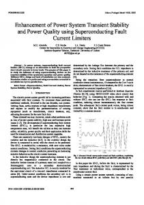
Time settling for terminal voltage and frequency deviations are fixed at 0.4 and 20 seconds till the responses passes their oscillations and become stable. Simulations results indicate the responses of RBF AVR and PID LFC controllers in order to see the enhancement in stability of power system. Fig. 3(a-b) shows the Vt response (a) without controller and (b) with conventional PID AVR controller. Fig. 3 (c-d) shows Vt responses (c) with RBF AVR (d) with RBF AVR and PID LFC controllers. Fig. 3(d), clearly indicates that there is no change in Vt response having PID LFC controller. Because in Fig. 3(c), RBF AVR is showing and excellent improvement which is exactly same in Fig 3(d). It
For this application two-layer network has been created.
means there is no impact of LFC controller on AVR
The input or first layer takes radial basis transfer function
excitation system of synchronous machine. These all
neurons which calculates its weighted inputs and its net input with net product. The second layer takes linear transfer function neurons and calculates its weighted inputs with dot product and its net inputs with net sum. First and second both layers have biases. At first no neuron is available in radial basis transfer function and FF network architectures with two-layer
responses have been combined in Fig. 3(e) and Fig. 4 in large.
4.2
Frequency/Speed Deviation Responses
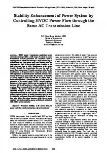
Frequency deviation responses without LFC controller (a), with PID AVR (b), PID-LFC and RBF-AVR (c) and RBFLFC and RBF-AVR (d) are shown in Fig. 5(a-d) and combined responses are illustrated in Fig. 5(e) respectively.
Mehran University Research Journal of Engineering & Technology, Volume 31, No. 3, July, 2012 [ISSN 0254-7821] 532
Design of FNN AVR for Enhancement of Power System Stability Using Matlab/Simulink
The in large view of Fig. 5(e) is shown in Fig. 6. These all responses show good improvement in stability but again prove that there is no coupling impact between AVR and LFC controllers. Hence both RBF AVR and RBF LFC controllers have their excellent own responses separately which is verified from their results because transient, small signal and dynamic stability improves efficiently.
The suggested method of designing RBF AVR is easy to implement with the help Matlab/simulink software. In order to validate the simulated results, the propose AVR is compared with conventional AVR. These results show that the RBF AVR controller has promising satisfactory generalization applicability and suitability as well as accuracy.
using Matlab/Simulink and neural network toolbox has
RBF AVR is more suitable where various types of disturbances at different times occur as in case of power system. It also ensures superior responses at different load conditions. Due to fast acting and settling, proposed AVR is more suitable for transient and small signal stability of the system.
been successfully demonstrated. The proposed technique
ACKNOWLEDGEMENTS
5.
CONCLUSIONS
RBF AVR controller with OLS algorithm, in SMIB with linearized model of SM and excitation system as model
controls terminal voltage and reactive power thereby improving transient stability of the system and eliminates the drawbacks of conventional AVR control system.
FIG. 3(a-e). TERMINAL VOLTAGES RESPONSES
Authors acknowledge with thanks the higher authorities and Department of Electrical Engineering, Quaid-e-Awam University of Engineering, Science & Technology, Nawabshah, Sindh, Pakistan ,and Mehran University of Engineering & Technology, Jamshoro, Sindh, Pakistan, for continuous encouragement and time to time facilities when required during this research work, which is an attempt for Ph.D work.
FIG. 4. COMBINED ALL TERMINAL VOLTAGES (IN LAGER)
Mehran University Research Journal of Engineering & Technology, Volume 31, No. 3, July, 2012 [ISSN 0254-7821] 533
Design of FNN AVR for Enhancement of Power System Stability Using Matlab/Simulink 0.05 0 -0.05
0
2
4
0
2
4
0
2
0
0
0.05
6 8 10 12 14 16 (A) WITHOUT CONTROLLERS
18
20
0
Frequency/Speed Deviation
-0.05
6
8 10 12 14 (B) WITH PID-AVR
16
18
20
4
6 8 10 12 14 (C) PID-LFC & RBF-AVR
16
18
20
2
4
6 8 10 12 14 (D) RBF-LFC & RBF-AVR
16
18
20
2
4
0.05 0
-0.05 0.05 0
-0.05 0.05 0 -0.05
6
8 10 12 14 16 18 20 Time (Seconds) (E) COMBINED RESPONSES WITH CONTROLLERS
FIG. 5(a-e). FREQUENCY/SPEED RESPONSES
FIG. 6. COMBINED ALL FREQUENCY RESPONSES (IN LARGE)
APPENDIX-A List of Notations A,B,C System polynomials D Damping coefficient EB or V∞ Infinite bus bar voltage Ed Direct axis voltage Efd or EFD Field voltage E’ q Quadrature axis voltage Et or Vt Generator terminal voltage H Inertia constants IF Field current Constants of the linearized model K1-K6 KA Regulator amplifier gain Damping factor KD KE Exciter gain Stabilizing transformer gain KF Generator gain KG Kg Governor gain KP, K1, KD Proportional, integral and derivative (PID) controller gains KR Sensor gain KT Turbine gain Le or Xe Transmission line inductance or reactance P or P e Generator real or electrical power Pg Governor power PL Load real power Pm Mechanical power input Q Reference real power QL Generator reactive power rF Load reactive power QL Field resistance R Speed regulation of governor Re Transmission line resistance (s) Shows Laplace transformation Te Electrical torque Tm Mechanical torque Vd,Vq Direct and quadrature axis voltages Ve Error voltage vF Field voltage VF Exciter voltage VL Load voltage VR Regulator amplifier voltage Vrefs Reference voltage VS Sensor voltage Xd,Xq Direct and quadrature axis reactances x’d,z’q Direct and quadrature transient axis reactances δ Generator rotor angle δΑ Regulator amplifier time constant τE Exciter time constant τF Stabilizing transformer time constant τG Generator time constant τg Governor time constant τR Sensor time constant τT Turbine time constant ω Angular speed ωR Rated angular speed ωref Reference speed Δ Shows change λd Direct axis flux linkages λq Quadrature axis flux linkages [2-4]
Mehran University Research Journal of Engineering & Technology, Volume 31, No. 3, July, 2012 [ISSN 0254-7821] 534
Design of FNN AVR for Enhancement of Power System Stability Using Matlab/Simulink APPENDIX-B
REFERENCES
The numerical values of various components as well as other constants required developing simulation model.
[1]
Schleif, F.R., Hunkins, H.D., Martin, G.E., and Hattan, E.E., "Excitation Control to Improve Power Line Stability", IEEE Transactions on Power Systems,
For turbine and governing systems
Volume 87, pp. 1426-1434, 1968. Kg=1.0, τg=0.2, KT=1.0, τT0.5m R=0.05
[2]
deMello, F.P., and Concordia, C., "Concepts of Synchronous Machine Stability as Affected by Excitation
SMIB (Synchronous Generator and Constants of Linear Model)
Control," IEEE Transactions on Power Systems, D=0.1, H=5, K 1=1.5, K T=0.2, K 4=1.4, K 5=-0.1, K 6=0.5, K G=0.8, τ G=1.5 Values for excitation model KE=1.,0, τ E=0.4, KA=1.10, τA=0.1, KR=1.0, τR=0.05 K1 is the change in electrical torque for a small change in rotor angle at constant d axis flux linkage; i.e.the synchronizing torque coefficient
K1 =
TeΔ δΔ
[3]
Anderson, P.M., and Fouad, A.A., "Power System Control and Stability", Iowa State University Press, Iowa, USA, 1977.
[4]
Kundur, P., “Power System Stability and Control, 4th Edition, McGraw-Hill Inc., 1994
⎤ ⎥ E′qΔ ⎦
[5]
Saddat, H., “Power System Analysis”, 1st Edition, McGraw-Hill Inc., 1999.
K2 is the change in electrical torque for small change in the d axis flux linkage at constant rotor angle
K2 =
Volume 88, pp. 316-329, 1969.
[6]
Hsu, Y.Y.S., Shyue, W., and Su, C.C., "Low Frequency Oscillations in Longitudinal Power Systems, Experience
⎤ ⎥δ = δ0 E′qΔ ⎥ ⎦ TeΔ
with Dynamic Stability of Taiwan Power System", IEEE/ PES, Winter Meeting, New York, 1986.
τ’d0 is the direct axis open circuit time constant of the machine.
[7]
Moussa, H.A.M., and Yu, Y.N., "Optimal Power System Stabilization Through Excitation and/or Governor
K3 is an impedance factor and
Control", IEEE Transactions on Power Systems,
( )]
Volume 91, pp. 1166-1174, 1972.
K3 final value of unit step VF response = lim E′Δ t δ Δ = 0 t →∞ K4 is the demagnetizing effect of a change in the rotor angle (at steady state) K4 = −
1 K3
( )]
VtΔ ⎤ ⎥ E′q δΔ ⎦
IEEE Transactions PAS, Volume 102, pp. 1738-1746,
()
1983. [9]
Yu, Y.N., and Siggers, C., "Stabilization and Optimal Control Signals for a Power System", IEEE TP-531 Summer Power Meeting and EHV Conference, July, 1970.
= E′q0
[10]
⎤ ⎥δ = δ0 E′qΔ ⎥ ⎦
ANSI/IEEE Std 122 (1985), IEEE Recommended Practice for Functional and Performance Characteristics of Control Systems for Steam Turbine-Generator Units,
K6 is the change in terminal voltage Vt for a small change in the d axis flux linkages at constant rotor angle, or [2-4]
K6 =
Chan, W.C., and Hsu, Y.Y., "An Optimal Variable Structure Power System Stabilizer for Power System Stabilization",
lim E′ t v FΔ = 0, δ Δ = u t t →∞ Δ
K5 is the change in the terminal voltage Vt for a small change in rotor angle at constant d axis flux linkage, or
K5 =
[8]
The Institute of Electrical and Electronics Engineers, USA, 1985.
VtΔ
[11]
Neibur, D., "Artificial Neural Networks for Power Systems", Report by TF 38.06.06, Electra No. 159, April, 1995.
Mehran University Research Journal of Engineering & Technology, Volume 31, No. 3, July, 2012 [ISSN 0254-7821] 535
Design of FNN AVR for Enhancement of Power System Stability Using Matlab/Simulink [12]
Howard, S., "Neural Networks in Electrical Engineering",
[19]
Memon, A.P., "Artificial Neural Network Applications in Electrical Alternator Excitation Systems", M.Phil, Thesis, Mehran University of Engineering & Technology, Jamshoro, Sindh, Pakistan, 2002.
[20]
Powell, M.J.D., "Radial Basis Functions for Multivariable Interpolation", A Review, Proceedings IMA Conference on Algorithms for the Approximation of Functions and Data, RMCS, pp. 143-167, Shrivenham, UK, 1985.
[21]
Chen, S., Cowan, C.F.N., and Grant, P.M., "Orthogonal Least Squares Algorithm for Radial Basis Function Networks", IEEE Transactions on Neural Networks, Volume 2, No. 2, pp. 302-309, 1991.
[22]
Gurrala, G., and Sen, I., "A Modified Heffron-Phillip's Model for the Design of Power System Stabilizers", Power System Technology and IEEE Power India Conference, 2008.
[23]
Prathap, D., and Krishna, H., et al., "Design of Power System Stabilizer To Improve Small Signal Stability by Using Modified Heffron-Phillip's Model", International Journal of Engineering Science, & Technology, Volume 3, No. 6, pp. 4888-4896, June, 2011.
[24]
MATLAB Neural Network Toolbox Version 7.0.2 (R2011b), User's Guide, The Mathworks Inc., 2011 http://www.mathworks.com, (Visited on December, 2011.
Proceedings of the ASEE New England Section, Annual Conference 2006. [13]
[14]
[15]
Strefezza, M., and Dote, Y., "Radial Basis Neural Network Adaptive Controller for Servomotor", IEEE, Transactions on Power Systems, Volume 2, pp. 413-417, 1993. Warwick, K., Irwin, G.W., and Hunt, K.J., "Neural Networks for Control and Systems", 1st Edition, Peter Peregrinus Ltd., UK, February, 1992. Suykens, J.A.K., "Artificial Neural Networks for Modelling and Control of Non-Linear Systems", 1st Edition, Kluwer Academic Publishers, 1996.
[16]
Fausett, L., "Fundamentals of Neural Networks, Architectures, Algorithms and Applications", 2nd Edition, Prentice Hall, 1994.
[17]
Tanaka, K., "An Approach to Stability Criteria of Neural Network Control Systems", IEEE Transactions on Neural Networks, Volume 7, No. 3, pp. 629-642, May, 1996.
[18]
Unar, M.A., and Murry, D.J., "Automatic Steering of Ships Using Neural Networks", International Jouranl Adaptive Control Signal Process, Volume 13, pp. 203-218, 1999.
Mehran University Research Journal of Engineering & Technology, Volume 31, No. 3, July, 2012 [ISSN 0254-7821] 536