Available online at www.sciencedirect.com
Energy Procedia 34 (2013) 362 – 370
10th Eco-Energy and Materials Science and Engineering (EMSES2012)
Design of MATLAB/Simulink Modeling of Fixed-Pitch Angle Wind Turbine Simulator Phlearn Jansuya and Yuttana Kumsuwan* Department of Electrical Engineering, Faculty of Engineering, Chiang Mai University 239, Huay Keaw Road, Chiang Mai, 50200 THAILAND
Abstract This paper presents the model of fixed-pitch angle wind turbine simulator. The purposed dynamic model consists of wind turbine profiles which attribute to the mechanical power and torque characteristics of wind turbine. The objective of this research is to develop and design the fixed-pitch angle wind turbine simulator. The analytical model has been derived representing the wind turbine simulator, to describe the simulation results using a MATLAB/Simulink. The system has been simulated to verify the effectiveness of the fixed-pitch angle wind turbine simulator at over rated rotational speed. The wind turbine simulator can propel an induction generator model. This implies the characteristics of the electrical power. The wind turbine simulator can display mechanical power and torque characteristics following to the wind velocity. The torque from the wind turbine simulator can be used to drive the induction generator to generate the active power fed into the load.
2013 The Authors. Published by Elsevier B.V. ©©2013 The Authors. Published by Elsevier B.V. Open access under CC BY-NC-ND license. Selection andand/or peer-review under responsibility of COE of Sustainalble System, Rajamangala University of Technology Selection peer-review under responsibility of COE Energy of Sustainable Energy System, Rajamangala Thanyaburi University(RMUTT) of Technology Thanyaburi (RMUTT) Keywords: Wind energy; wind turbine simulator; pitch angle; induction generator
1. Introduction In recent years, due to decreases of fossil fuels, the energy shortage and environment pollution are the important problems for the human lives and social development. Traditional mineral energy such as coal, oil and gas will be used out in a few years and will cause serious environmental problems. So the
* Corresponding author. Tel.: +66-5364-4140 to 311; fax: +66-5364-4195. E-mail address:
[email protected].
1876-6102 © 2013 The Authors. Published by Elsevier B.V. Open access under CC BY-NC-ND license.
Selection and peer-review under responsibility of COE of Sustainalble Energy System, Rajamangala University of Technology Thanyaburi (RMUTT) doi:10.1016/j.egypro.2013.06.764
Phlearn Jansuya and Yuttana Kumsuwan / Energy Procedia 34 (2013) 362 – 370
renewable energy, especially wind energy and solar energy have become more and more considerable all over the world [1], [2]. In the wind energy conversion system, the wind turbine captures the wind energy. Then the generator converts it to the electrical power. So the characteristic of the wind turbine is very important. Because the wind turbine is big and expensive, it is not convenient to do the research in the practical wind farm. For the research on wind power technology, it is necessary to construct a simulator to simulate not only wind turbines without reliance on natural wind turbine simulator can reduce experimental cost and shorten research and development cycle of the new technologies. To develop a wind turbine simulator which can simulate the real wind turbine in the steady state and dynamic state is very meaningful for laboratory research. It can improve research effectiveness and efficiency. Wind turbine simulators are important equipments for developing wind energy conversion systems and are used to simulate wind turbine behavior in a controlled environment without reliance on natural wind resources, for the purpose of research and design into wind turbine drive trains, especially energy conversion systems. Wind turbine simulators can significantly improve the effectiveness and efficiency of research and design in wind energy conversion systems. The simulator can be used for research applications to drive an electrical generator in a similar way as a wind turbine, by reproducing the torque developed by a wind turbine for a given wind velocity. Also, it can be used as an educational tool to teach the behavior, operation and control of a wind turbine. Usually induction motor, separately excited DC motor and permanent magnet synchronous motor can be used to reproduce the static and dynamic characteristics of real wind turbines. A few research works about wind turbine simulator have been done in the past few years. There have been some studies on wind turbine simulator based on DC motor [3]-[5], induction machine, [6], [7] and permanent magnet synchronous machine (PMSM) [8]. In [3] presented a wind turbine simulator based on a DC machine. The armature and the field current were controlled so that the DC machine can generate the static characteristics of a wind turbine, which is easy to control and its dynamic characteristics are excellent. In [6] presented an IGBT inverter-controlled squirrel cage induction motor (IM) instead of a dc motor. In addition, an intelligent power module (IPM) inverter was used to control the PMSM. Wind turbine simulator based on PMSM has some advantages such as high power density, small size, high precision and easy to control [8]. This paper study demonstrates the design and the construction of model of operation simulator of fixed-pitch angle wind turbines that is able to simulate the actual operation of wind turbines, with regard to fixed-pitch angle wind turbines to distribute the highest rate of mechanical power of wind turbines. The approach of this study is to show the design and the construction of operation simulator of wind turbines by using MATLAB/Simulink program. This paper is organized as follows; Section 2 discusses the characteristic. The proposed the control of wind turbine is presented in Section 3. The validity of the proposed method is confirmed on simulation results in Section 4. The conclusions will be given in Section 5. 2. Characteristic of Wind Turbine The configuration of a wind generation system is shown in Fig. 1. Wind turbines produce electricity by using the power of the wind to drive an electrical generator. Wind passes over the blades, generating lift and exerting a turning force. The rotating blades turn a shaft inside the nacelle, which goes into a gearbox. The gearbox increases the rotational speed to that which is appropriate for the generator, which uses magnetic fields to convert the rotational energy into electricity energy.
363
364
Phlearn Jansuya and Yuttana Kumsuwan / Energy Procedia 34 (2013) 362 – 370
Gear Box
Te Generator
vw
w
Tm
e
Wind Turbine
Fig. 1. Wind generation system configuration.
The rotor is the component designed to extract the energy from wind. The power which the rotor can extract from the wind can be defined by the difference between the power in the moving air force and after the rotor. Based on the Betz theory, the mechanical power Pm extracted from wind energy can be written as [9], [10]
Pm =
1 pC p (l , b )r vw3 R 2 2
(1)
where C p (l , b ) is the wind power coefficient, r is the air density (1.25 kg/m3), vw is the wind speed (m/s), and R is the wind blade radius (m). From above equation, the aerodynamic efficiency of a wind turbine is described by the power coefficient ( C p ) function, which is dimensionless and nonlinear. The two parameter C p = f (l , b ) variables that influence the efficiency are the blade pitch angle b and tip speed ratio l . The tip speed ratio is defined to be the ratio between the wind speed and the rotor speed, which is defined as
l =
ww R vw
(2)
where ww is the rotor angular speed of the wind turbine shaft or the generator shaft (rad/s). The general function defining the power coefficient C p as a function of the tip speed ration and the blade pitch angle is defined as [11]
C p (l , b ) = c1
c2 - c3 b - c4 e li
- c5 li
+ c6l
(3)
where the coefficients c1 - c6 depend on the various wind turbines. The proposed coefficients are equal to: c1 = 0.5176, c1 = 0.5176, c2 = 116, c 3 = 0.4, c 4 = 5, c5 = 21 and c6 = 0.0068. Additionally the parameter l i is defined as 1 1 0.035 = - 3 (4) li l + 0.08b b + 1
365
Phlearn Jansuya and Yuttana Kumsuwan / Energy Procedia 34 (2013) 362 – 370
The mechanical torque T m developed by the wind turbine can be obtained from (1) and expressed in terms of the torque coefficient C t
Tm =
Pm 1 = pC t (l , b )r vw2 R 3 ww 2
(5)
Therefore, the relationship between the torque and power coefficients is given by wR P = t C t (l , b ) = l C t (l , b ) C p (l , b ) = p m 2 3 vw r R vw 2
vw w
w
R
vw
1g
Cp
,
Cp
(6)
1 Cp 2
,
Pm
vw3 R 2
Pm Wind Turbine
Tm
w
Fig. 2. Block diagram wind turbine characteristic
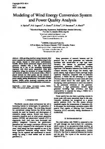
Fig. 2 shows the block diagrams representation of the wind turbine characteristic. The inputs for the wind turbine characteristic are wind speed, rotor speed, and blade pitch angle. The outputs are the mechanical power and torque, which drives the electrical generator.
Fig. 3. Power coefficient and torque coefficient versus tip speed ratio
Fig. 3 shows a wind turbine power coefficient and torque coefficient versus tip speed ratio for a fixedpitched wind turbine ( b = 0 ), which corresponds to the C p and C t versus l characteristic used in the
366
Phlearn Jansuya and Yuttana Kumsuwan / Energy Procedia 34 (2013) 362 – 370
turbine emulation of this study. It can be seen that a maximum power coefficient ( C p,max = 0.48) is achieved at only one optimum tip speed ration, l opt = 8.1. 3. Closed of Wind Turbine The power characteristics of a wind turbine are defined by the power curve, which relates the performance that is guaranteed by the manufacturer. The International Energy Association (IEA) has developed recommendations for the definition of the power curve. The recommendations have been continuously improved and adopted by the International Electrotechnical Commission (IEC). The standard, IEC61400-12, is generally accepted as a basis for defining and measuring the power curve [12]. A typical power curve is characterized by three wind speeds: cut-in wind speed, rated wind speed and cut-out wind speed as described in Fig. 4. As it can be seen from Fig. 4, the wind turbine starts to capture power at the cut-in wind speed. The power captured by the blades is a cubic function of wind speed until the wind speed reaches its rated value. To deliver captured power to the grid at different wind speeds, the wind generator should be properly controlled with variable speed operation. As the wind speed increases beyond the rated speed, aerodynamic power control of blades is required to keep the power at the rated value. This task is performed by three main techniques: passive-stall, active-stall, and pitch control [13]. The wind turbine should stop generating power and be shut down when the speed is higher than the cutout wind speed. Note that the theoretical curve of Fig. 4 has an abrupt transition from the cubic characteristic to the constant power operation at higher speeds. However, practical turbines do not exhibit this behaviour, and the transition is smoother [14].
Pm Rated power
Generator control Theoretical power curve
Stall or pitch control Practical power curve
Parking mode
Parking mode
Operating region
Min. power Cut-in
Rated
Cut-out
vw (m/s)
Fig. 4. Qualitative wind turbine mechanical power versus wind speed curve
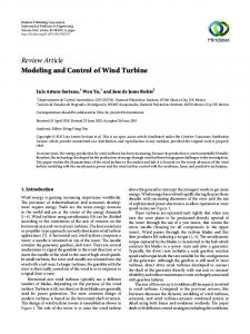
4. Simulation Results The proposed dynamic model of the variable speed wind turbine is developed in MATLAB/Simulink. In this paper, a variable speed induction generator wind generation system is also considered. The detail parameters of the wind turbine and induction generator are shown in Table 1 and Table 2, respectively. Fig. 5 shows several wind turbine-mechanical power versus rotor speed characteristics, which can be obtained with the wind velocity as a parameter. It can be seen that the maximum power line for increasing wind velocities up to rated. The curves indicate that the maximum power point increases and decreases as wind speed rise and falls.
Phlearn Jansuya and Yuttana Kumsuwan / Energy Procedia 34 (2013) 362 – 370
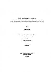
The turbine mechanical torque versus speed characteristics are shown in Fig. 6. From Fig. 5 and 6 the maximum power line is not the same as the maximum toque line. Table 1. Parameters of the wind turbine Parameter Rated power (kW) Wind blade radius (m) Rated wind speed (m/s) Cut-in speed (m/s) Maximum wind speed (m/s) Gear box ratio
Value 1 1.04 10 4 12 2
Table 2. Parameters of the induction generator
Parameter
Value
Rated power (kW)
1.1
Rated voltage (V)
415
Rated current (A)
2.77
Rated frequency (Hz) Rated speed (rpm) Number of poles
Fig. 5. Power-speed characteristics of a wind turbine
50 1415 4
367
368
Phlearn Jansuya and Yuttana Kumsuwan / Energy Procedia 34 (2013) 362 – 370
Fig. 6. Torque-speed characteristics of a wind turbine
In Fig. 7, wind speed, power coefficient, tip speed ratio, and torque transient waveforms of the wind turbine are represented in start-up conditions under a constant wind speed. Fig. 7 (a) shows wind speed vw at 10 m/s, which is fluctuating with non-uniform distribution. Fig. 7 (b) shows transient waveform of power coefficient C p . It should also be noted that the system is operating at an almost maximum power coefficient most of the time. Fig. 7 (c) shows the corresponding tip speed ratio. The response of the mechanical torque T m under a constant wind speed is shown in Fig. 7 (d). Fig. 8 shows simulated transient waveforms of the induction generator under start-up characteristic. Fig. 8 (a) shows the phase voltage and current va , ia . The electromagnetic torque T e response during the generator free acceleration is shown in Fig. 8 (b). Fig. 8 (c) shows rotor speed n r of the induction generator. The active powers of the wind turbine simulator Pm and induction generator Pe are shown in Fig 8 (d). Fig. 9 and Fig. 10 show the simulation results for step change of the wind speed.The wind speed used to obtain the simulation results is present in Fig. 9 (a). A variation in ramp, during a period from 0.5 s 1.5 s, has linearly changed between 7 m/s to 12 m/s to verify the all range operation of the wind turbine simulator. Fig. 9 (b) and Fig. 9 (c) show simulated waveforms of power coefficient C p and the tip speed ratio. It can be seen that the system is operating at the variation of wind speed. The response of the mechanical torque T m under a variable wind speed is shown in Fig. 7 (d). Fig. 10 shows simulated induction generator waveforms of phase voltage and current, electromagnetic torque, rotor speed, and active powers. Fig. 10 (a) shows the phase voltage and current va , ia . The electromagnetic torque T e response during the variation of wind speed is shown in Fig. 10 (b). Fig. 10 (c) shows rotor speed n r of the induction generator, which follow the wind speed variation. The difference between generator electrical power and turbine power is shown in Fig. 10 (d). The active powers of the wind turbine simulator Pm and induction generator generate maximum power according to the variation of wind speed. The maximum power transmitted to the load is 1.1 kW when the maximum wind speed of 12 m/s.
Phlearn Jansuya and Yuttana Kumsuwan / Energy Procedia 34 (2013) 362 – 370
Fig. 7. Simulated waveforms of the wind turbine characteristic under a constant wind speed
Fig. 8. Simulated waveforms of the induction generator during free acceleration under a constant wind speed
Fig. 9. Simulated waveforms of the wind turbine characteristic under a variable wind speed
Fig. 10. Simulated waveforms of the induction generator under a variable wind speed
369
370
Phlearn Jansuya and Yuttana Kumsuwan / Energy Procedia 34 (2013) 362 – 370
5. Conclusion This paper has presented the modeling of fixed-pitch angle wind turbine simulator by using a MATLAB/Simulink program. The purpose of the modeling wind turbine simulator has been: 1) to identify the mechanical power and torque when a variable wind speed velocity and 2) thereby identify the power flow of an induction generator into the load. The functionality of the proposed wind turbine simulator scheme is validated by simulation results. Acknowledgements The work was supported by the Faculty of Engineering, Chiang Mai University. References [1] Chinchilla, M. Arnaltes, S. and Burgos, J. C. 2006. Control of permanent-magnet generators applied to variable-speed windenergy systems connected to the grid. In IEEE Trans. Ener. Conver. vol. 21, no. 1, p. 130-135. [2] Kojabadi, H. M. Chang, L. and Boutot, T. 2004. Development of a novel wind turbine simulator for wind energy conversion systems using as inverter-controlled induction motor. In IEEE Trans. Ener. Conver. vol. 19, no. 3, p.547-552. [3] Nunes, A. A. C. Seixas, P. F. Cortizo, P. C. and SilvaS. R. 1993. Wind turbine simulator using a DC machine and a power reversible converter. In Proc. Int. Conf. Elect. Mach., vol. 3, Adelide, Australia, p. 536 540. [4] Ovanda, R. Aguayo, J. and Cotorogea, M. 2007. Emulation of a low power wind turbine with a DC motor in Matlab/Simulink. In Pow. Electr. Specialist Conf., p.859-864. [5] Li, W. Xu, D. G. and Zhang, W. 2007. Research on wind turbine emulation based on DC motor. In IEEE conf. Ind. Elect. And Appli., p. 2589-2593 [6] Kojabadi, H. M. Chang, L. and Boutot, T. 2004. Development of a novel wind turbine simulator for wind energy conversion systems using an inverter-controlled induction motor. In IEEE Trans. Ener. Conver., vol. 19, No. 3, p. 547 552. [7] Jia, Y. Q. Wang, Z. A. and Yang, Z.Q. 2007. Experimental study of control strategy for wind generation system. In IEEE Pow. Electr. Specialist Conf., p.1202-1207 [8] Xu, K. Hu, M. Q. and Yan, R. Y. 2007. Wind turbine simulator using PMSM. In International Universities Power Eng. Conf., p. 732-737. [9] Koutroulis, E. And Kalaizakis, K. 2006. Design of a maximum power tracking system for wind-energy-conversion applications. In IEEE Trans. Ind. Electron., vol 53, no. 2, p. 486-494. [10] Fan, Y. Chau, K. T. and Niu, S. 2006. Developed of a new brushless doubly fed doubly salient machine for wind power generation. In IEEE Trans. Magn. vol. 42, no. 10, p. 3455-3457. [11] Heier, S. 1998. Grid integration of wind energy conversion systems. John Wiley & Sons Ltd. [12] Wu, B. Lang, Y. Zargari, N. and Kouro, S. 2011. Power conversion and control of wind energy systems. Wiley. [13] Ackermann, T. 2005. Wind power in power system. Wiley. [14] Hau, E. 2005. Wind turbines: fundamentals, technologies, application, economics. 2nd edition. Spring.