Reactor with Coolant Fluid of H2O on Sub Channel Hexagonal ... of passive cooling systems as well as systems integration to the Generation III + nuclear power.
IOSR Journal of Mechanical and Civil Engineering (IOSR-JMCE) e-ISSN: 2278-1684,p-ISSN: 2320-334X, Volume 12, Issue 5 Ver. I (Sep. - Oct. 2015), PP 66-71 www.iosrjournals.org
Design of Model Test on Nuclear Reactor Core of Small Modular Reactor with Coolant Fluid of H2O on Sub Channel Hexagonal Erwin Dermawan1, Syawaluddin2, Anwar Ilmar Ramadhan3*, Ery Diniardi4, Sandy Adrian5 1
Department of Electrical Engineering, University of Muhammadiyah Jakarta, Indonesia Department of Mechanical Engineering, University of Muhammadiyah Jakarta, Indonesia
2,3,4,5
Abstract : Nuclear energy intends to peaceful purposes include the construction of Nuclear Power Plant and the construction of the reactor can be used as research for the purposes of science, research, education, and others. The purpose of this research is to create a concept design of test equipment in a nuclear reactor core in sub channel hexagon software using Computer Aided Design. In this research, the simulation process is determined by the size of the pitch distance and Pitch / Diameter (P / D) = 1.58, on the design of a nuclear reactor core test equipment that has a length of 40 cm active heating to be investigated phenomena velocity flow rate passing through the sub-channel. It happened changes in temperature due to particle cooling fluid flowing through a solid object that has a cylindrical thermal energy of 500 000 W/m 2 and carried away by the flow rate at a velocity of 3 m/s. This research resulted in design visualization tool that can test a design to prototyping in design methods and based on the results of the discussion of the design has been impassable factor natural convection and forced convection of the simulation process use CFD Code. Keywords – Design; Nuclear Reactor; Sub Channel; Heat Transfer; Computational Fluid Dynamics
I.
Introduction
During power generation using fossil fuels such as oil, coal, and so on. It is an energy intake that cannot be updated. Therefore, it is necessary to use alternative energy. One of the new and renewable energy or renewable energy from power plants using fossil fuels is nuclear energy. [1, 2] Cannot be separated from the human factor needs nuclear energy is very likely to be developed by professional experts in the field of research into alternative energy transportation fuels such as cars, motorcycles, trains, planes, and others. Utilization of nuclear energy intends to peaceful purposes include the construction of a power reactor nuclear power plant and the construction of the reactor can be used as research for the purposes of science, research, education, and others. [3, 4, 5, 6] Phenomena occur in the convection flow into a turbulent or laminar including also affect the heat transfer coefficient. In NPP (Nuclear Power Plant) for this study used one type of reactor with low power that SMR (Small Modular Reactor) [7]. Magnitude thermal-hydraulics such as pressure, coolant flow rate and temperature of the fuel needs to be known, for example through the prediction calculations. For the development and application of nuclear reactor Small Modular Reactor (SMR) technology was developed for the implementation of passive cooling systems as well as systems integration to the Generation III + nuclear power plants. With leading technology and the power generated, it ought to be explored and researched the design and technology of nuclear reactor Small Modular Reactor CAREM type-25 for one of the new and renewable energy sources in Indonesia [8].
II.
Method research
Methodology or approach that will be done is to use CAD software to advance. To perform the simulation process based on the literature used. Step-by-step methodology, as follows: a. Finding the literature on the design of a nuclear reactor core in sub channel hexagonal b. Creating test equipment design using CAD (Computer Aided Design) Code to get the size of each part of the component parts and unite with other components. c. Creating geometry modeling using CFD Code, for a nuclear reactor core by using numerical method in CFD to obtain data of temperature distribution in the fluid flow rate sub channel.
III.
Results And Discussion
Things that need to be done first for designing test equipment models of nuclear reactor core at the sub channel arrangement of hexagons there are several things to consider, among others, each individual component must have the right size and diameter to avoid mistakes in the process of designing. To find out how large dimensions, sizes, which will be used in the early design process, the use of CAD software to design the component code. Below is the data component test equipment, Table 1. DOI: 10.9790/1684-12516671
www.iosrjournals.org
66 | Page
Design of Model Test on Nuclear Reactor Core of Small Modular Reactor with Coolant Fluid… Table 1. Data of Component Model of Test Equipment Part Test section Test section main Distributor Stand Test Section Main Spacer Heating Cylinder hanger Cylinder heating Tank of 1 Tank of 2
Length [mm] 400 300
Width [mm] 400 100 55.8 300
Dimension Height [mm] 1000 700 100 152
Diameter [mm] 20 30 30
Thickness [mm] 8 5 8 5
295 300
295 350
-
20 20
2 2
400 400 400
400 400
650 400 400
19.5 30
1.8 5 5
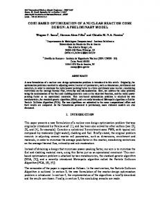
Component Model with CAD Part is a two-dimensional object using the sketch by forming a pattern on each menu is used as line, circle, center, polygons, and so on. Then made into a 3-dimensional object using the method in which there is a menu features extrude, revolve, and extrude cut, shell, and so forth, so it can complete a design of any size, diameter, and specific dimension. Assembly is a document in which at any parts, features, and other assembly (Sub Assembly) paired or grouped together. In general, the assembly process took several components of parts, each of these components are collected in one place and then the components are united by choosing mate that where there is a standard menu which consists of coincident, parallel, and so on. The following is an image of the model developed test equipment, Figure 1.
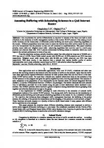
Figure 1. Design Component Test Equipment of Small Modular Reactor Specification: a. Heating Cylinder hanger, b. Spacer, c. Test section Main, d. Cylinders Heating, e. Distributor, f. Stand Test Section Main, g. Section Test. Water Supply System For water supply system at test equipment section serves as a cooling fluid in the test section is designed with a system consisting of two water tanks, water pumps, water tap (1, 2, 3, 4, 5), flow meter = FM and pipe installation. 1 water tank placed in the position under section table test equipment and water tank 2 is placed in a position adjacent to the section test equipment. Water storage tank located at 1 in flush into the test section by using a centrifugal pump with water speed indicated on the pump specification, see Figure 2.
DOI: 10.9790/1684-12516671
www.iosrjournals.org
67 | Page
Design of Model Test on Nuclear Reactor Core of Small Modular Reactor with Coolant Fluid…
Figure 2. Scheme Water Supply System in Test Equipment Modeling Sub Channel Structure of Hexagonal use CFD Code The design of the reactor core models to be studied is composed of 7 pieces of rod-shaped pipe material stainless steel cylinder of diameter 1.95 cm and length 40 cm distance heating pipes pitch with 3.08 cm and ratio for Pitch / Diameter (P / D) is 1.58. (Figure 3)
Figure 3. Modeling the Test Reactor core of SMR in Sub Channel of Hexagonal Numerical Simulation by Using CFD Code Numerical simulation of the control volumes that have been made do with CFD Code and numerical modeling in this study using the CFD Code. For the manufacture of modeling requires several assumptions, namely: (1) Heat radiation from the outer wall and inner wall of the sub channel models hexagonal is ignored, (2) Heat conduction in the outer wall and inner wall of the sub channel models hexagonal is ignored. Characteristics of Fluid Flow on Forced Convection Heat Transfer in the Sub channel of Hexagonal Temperature changes occur as a result of the cooling fluid into the sub channel on the cylinder wall heater during ongoing movement. Cooling fluid molecules absorb energy particles heating cylinder so carried away by forced convection velocity. If the fluid velocity in the heater temperature will add a bit of growing to temperature changes temperature with constant heat flux. See Figure 4 to Figure 7.
DOI: 10.9790/1684-12516671
www.iosrjournals.org
68 | Page
Design of Model Test on Nuclear Reactor Core of Small Modular Reactor with Coolant Fluid…
Figure 4. Fluid velocity of vectors in Sub channel of hexagonal (sliced on the axis z = 0 m with Heat Flux = 500 000 W/m2)
Figure 5. Fluid velocity of vectors in Sub channel of hexagonal (sliced on the axis z = 0.2 m with Heat Flux = 500 000 W/m2)
Figure 6. Fluid velocity of vectors in Sub channel of hexagonal (sliced on the axis z = 0.4 m with Heat Flux = 500 000 W/m2)
Figure 7. Vector fluid velocity in Sub channel (with velocity = 0.3 m/s and constant heat flux is 500.000 W/m 2)
DOI: 10.9790/1684-12516671
www.iosrjournals.org
69 | Page
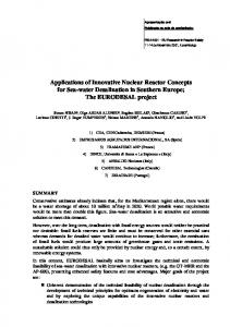
Design of Model Test on Nuclear Reactor Core of Small Modular Reactor with Coolant Fluid… Figure 6 and Figure 7 shows the distribution of the cooling fluid flow in forced convection heat transfer which passes through a narrow slit sub channel. From the figure it is seen that the distribution of the flow slowdown in the pace of the flow as it enters the cylinder sub channel wall heater. From the results obtained in the simulation process fluid temperature and the coolant temperature in the heating cylinder in sub channel is affected by the heat flux and velocity of fluid flow. Below are the data tables and graphs on the comparison between the simulation of natural convection conditions and forced convection on the constant heat flux 500000 W/m2 with a velocity of 0.05 and 0.3 m/s. Figure 8 to Figure 10, to determine the relationship between the ratio patterns fluid temperature and the temperature of the cylinder to constant heat flux is influenced by the flow rate. Temperature of Fluid (Tf) Temperature of Cylinder (Ts)
420 dem o
dem o
dem o
dem o
dem o
dem o
dem o
dem o
dem o
dem o
dem o
dem o
dem o
dem o
dem o
dem o
dem o
dem o
dem o
dem o
dem o
dem o
dem o
dem o
dem o
dem o
dem o
dem o
dem o
dem o
400
Temperature [K]
380
360
340
320
300 0.0
0.1
0.2
0.3
0.4
Distance [m]
Figure 8. Fluid Temperature relationship with temperature of cylinder in Sub Channel on constant heat flux 500 000 W/m2 at velocity of 0.05 m/s Temperature of Fluid (Tf) Temperature of Cylinder (Ts)
320 318
dem o
dem o
dem o
dem o
dem o
dem o
dem o
dem o
dem o
dem o
dem o
dem o
dem o
dem o
dem o
dem o
dem o
dem o
dem o
dem o
dem o
dem o
dem o
dem o
dem o
dem o
dem o
dem o
dem o
dem o
316
Temperature [K]
314 312 310 308 306 304 302 300 298
0.0
0.1
0.2
0.3
0.4
Distance [m]
Figure 9. Fluid Temperature relationship with temperature of cylinder in Sub Channel on constant heat flux 500 000 W/m2 at velocity of 0.3 m/s 420 d e m o
Natural Convection Tf [K] Natural Convection Ts [K] Force Convection Tf [K] Forced eConvection m o d e Ts m o [K]
d e m o
d e m o
400 d e m o
d e m o
d e m o
d e m o
d e m o
d e m o
d e m o
d e m o
d e m o
d e m o
d e m o
d e m o
d e m o
d e m o
d e m o
d e m o
d e m o
d e m o
d e m o
d e m o
d e m o
d e m o
d e m o
d e m o
d e m o
Temperature [K]
380
360
340
320
300 0.0
0.1
0.2
0.3
0.4
Distance [m]
Figure 10. The temperature difference in the temperature Cylinder and Fluid Temperature in Sub channel with Heat Flux 500 000 W/m2 at velocity 0.3 m/s DOI: 10.9790/1684-12516671
www.iosrjournals.org
70 | Page
Design of Model Test on Nuclear Reactor Core of Small Modular Reactor with Coolant Fluid… Figure 8 and Figure 9 shows the temperatures of the cylinder is higher than the temperature of the fluid due to the greater heating cylinder temperature and affect the temperature of the fluid that flows in the sub channel. The greater the heat flux, the higher the temperature of the cylinder wall temperature and fluid flow faster than the smaller cylinder wall temperature. This can be seen a comparison between natural convection and forced convection in Figure 10. Where it appears that the purple and green line is the graph of natural convection and the red and blue lines are forced convection. Higher natural convection compared with forced convection due to the difference in the speed of the cooling fluid flow.
IV.
Conclusion
From the results of modeling and simulation test equipment design has been done by using computeraided design programs and Computational Fluid Dynamics provides some conclusions as follows: (1) the data specifications of each component design can be used in the manufacture of test equipment design. (2) The results of the comparison between the variation of heat flux and flow rate with previous studies of different. (3) The lower the rate of fluid flow passing through the sub channel, the higher the temperature of the cylinder wall heater. (4) The smaller the heat flux supplied to the heating cylinder, the smaller the temperature in the cylinder wall heater. (5) The results of the design has been impassable factor natural convection and forced convection of process simulation.
References [1] [2] [3] [4] [5]
[6] [7] [8]
Diniardi, E., Ramadhan, AI, & Basri, H., “Literature Study of Design and Technology on Small Modular Nuclear Reactor (SMR) type CAREM-25”, 2013, 1, 1-6. Febriyanto, C., “Experimental Study of Natural Convection Heat Transfer, Forced, and the Mixed Sub-Channel Cylinder Hexagonal Structure”, Thesis Master program Science and Nuclear Engineering ITB, 2011, Bandung. Gimenez., MO, “CAREM Technical Aspects, Project and Licensing Status”, interregional workshop on Advanced Nuclear Reactor Technology, 2011, Vienna. Kim, SH, & El-Genk, MS, “Heat Transfer experiments for low flow of water in rod bundles”, 1989, Int. J. Heat Mass Transfer, 1321 – 1336. Supriyadi, J., “Experimental Study of Natural Convection Heat Transfer in the sub channel in Cylinder Vertical File Structur e Longitude Cage”, Proceedings of the 17th National Seminar on Technology and Nuclear Facilities Safety As well as the nuclear power plant, 2011, Yogyakarta Ramadhan, AI, Pratama, N., & Umar, E., “Simulation of Fluid Flow In 2000 TRIGA Reactor Using CFD CODE”, National Seminar of Basic Science, 2009, 1 - 6. Ramadhan, AI, Diniardi, E., & Sutowo, C., “Literature Study of nanofluids for Application Development in the Field of Engineering in Indonesia”, National Simposium of Application Technology I, 2013, M35-M40. Ramadhan, AI, Setiawan, I., & Satryo, MI, „Characteristics Simulation of Fluid Flow and Temperature Cooling (H2O) on Nuclear Reactor at core SMR (Small Modular Reactor)” Rotasi Journal, 2013, 15 (4), 33-40.
DOI: 10.9790/1684-12516671
www.iosrjournals.org
71 | Page