Available online at www.sciencedirect.com Available online at www.sciencedirect.com
Procedia Engineering
Procedia Engineering 00 (2011) 000–000 Procedia Engineering 29 (2012) 4223 – 4227 www.elsevier.com/locate/procedia
2012 International Workshop on Information and Electronics Engineering (IWIEE)
Design of Permanent Magnet Brushless DC Motor Control System Based on dsPIC30F4012 QingpingWua*, Wenchao Tianb a
ChangZhou College of information Technology,Changzhou 213164,China b Xidian University, Xian, 710071, China
Abstract The brushless DC motor has been promoted rapidly with the rapid development of the power electronics technology, microelectronic technology and rare earth permanent magnet materials. The brushless DC motor has a series of advantages of small volume, light weight, high efficiency and energy saving, easy speed regulation, simple structure, reliable operation and easy maintenance, etc, and it has been widely used in all areas of industrial control now. This paper mainly introduces the working principle of the permanent brushless dc motor and Microchip's motor dedicated digital signal controller—dsPIC30. The brushless DC motor control solutions with dsPIC30F4012 for control chip is proposed according to the fans and pumps load requirements, the hardware circuit is designed, and part of the source program is given. By designing hardware, writing control software, debugging and improving experimental system, it can be concluded that this system has superior control performance, reliability, and the product design requirements are achieved.
© 2011 Published by Elsevier Ltd. Open access under CC BY-NC-ND license. Keywords:Brushless DC Motor; PI Control; dsPIC30F4012
1. Introduction Brushless DC motor is composed of three major parts, motor body (the armature at the side of the stator, the permanent magnet at the side of the rotor), position sensors and electronic commutation circuit [1]. The working principle is as follows: with output signal of the position sensor which reflects the position of the rotor, electronic commutation circuit drives the corresponding power switching device with
* Corresponding author. Tel.: +86-013861238086 E-mail address:
[email protected].
1877-7058 © 2011 Published by Elsevier Ltd. Open access under CC BY-NC-ND license. doi:10.1016/j.proeng.2012.01.647
4224 2
QingpingW.Wu / Procedia00Engineering 29 (2012) 4223 – 4227 Mei and et al. Wenchao / ProcediaTian Engineering (2011) 000–000
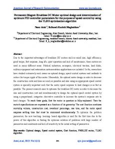
the armature winding connection, in turn makes the armature winding feed, thus generates jumping rotating magnetic field in the stator, and drives the permanent magnet rotor rotate. With the rotation of the rotor, position sensors constantly send signals, change the power state of armature windings, and make the conductor current direction remain unchanged under a pole. In the absence of mechanical contact body composed of commutator and brush body, the brushless DC motor has no commutation spark, while has a long life and reliable operation Therefore, it has been widely used under the load condition which requires long-term stable operation of the fan and pump. At present, with the extensive use of brushless DC motor, some internationally renowned semiconductor manufacturers have targeted this market, introduced the DSP chip for motor control system, also integrated together the microcontroller (MCU) control functions. In these chips ' platform, a high performance brushless DC motor numerical control system can be produced expediently. And as a rising star, Microchip Technology Inc has promoted a dsPIC30F digital signal controller with the PIC16 position monolithic integrated circuit as the core and in inlays DSP engine's. In the brushless DC motor control areas this controller has occupied a dominant position [2]. 2. Design Of Control System Based On The dsPIC30F Brushless Dc Motor Control system's DC motor uses the rare earth permanent brushless DC motor developed by Microchip Technology Inc. The brushless DC motor control program uses the typical three-phase six state circuits [3], and its main circuit diagram as shown in Fig. 1. The working principle is: 270V voltage supplied by the input power is applied on the three-phase power bridge formed by power MOSFET through a filter circuit. The three-way rotor position signal which is produced by Hall commutation detection and shaping circuit is processed by the PICF4012 and then the PWM control signal is produced. Through the power actuation module, three groups of electrical machinery square-wave slaving voltages are output, and then give the motor three-phase winding electric conduction in turn, thus actuate the motor rotating[4]. Rotate speed given
Auxiliary Power (Isolation)
Input filter circuit
DC24V
Bus voltage detection Bus current detection
dsPIC30F4012
Hall commutation detection and shaping Serial passage Interface Start / stop control
PWM pulse
MOS tube drive circuit
Three-phase fullbridge power conversion
Motor body
Simulation debugging Overcurrent fault
Filter circuit
DC270V
Over-temperature fault
Fig. 1. Control circuit main diagram
2.1 Design of dsPIC30F4012 peripheral circuit The peripheral circuit mainly contains the simulation connection, analog input connection, oscillating circuit, reset circuit, correspondence connection and so on. And the circuit is shown in Fig.2. The experiment proved that this peripheral circuit can make the chip work stably.
Qingping Wu and Wenchao Tian / Procedia Engineering 29000–000 (2012) 4223 – 4227 W. Mei et al. / Procedia Engineering 00 (2011)
Fig. 2. dsPIC30F4012 peripheral circuit
2.2 Design of MOS tube driving circuit and three-phase full-bridge power changing circuit In order to protect the logic circuit trouble-free service and produce enough large electric current to driver power MOS tube, certain installment to satisfy this function must be used. Infineon production, 6ED003L06-F is the special gate drive integrated circuit for MOS power components with the largest positive peak output drive current 440 mA. Through the internal bootstrap technique, external three high back pressure and fast recovery rectifiers D2,D3,D4 and the bootstrap capacitors C37-C42 can create enough current to drive the power MOS tube. The scheme uses a typical three-phase full-bridge power conversion circuit and the high voltage power SPW47N60C3 MOS tube. The maximum current is 47A and the maximum voltage is 650 V. The circuit is shown in Fig. 3.
Fig.3. MOS tube drive circuit and three-phase full-bridge power conversion
4225 3
4226 4
QingpingW.Wu / Procedia00Engineering 29 (2012) 4223 – 4227 Mei and et al. Wenchao / ProcediaTian Engineering (2011) 000–000
2.3 Design of bus current detection circuit and parameters In order to control the current effectively,the project may adopt current loop control,and need real-time accurate measurement of the bus current. And the specific circuit and parameters are shown in Fig. 4. AGND +5VA 5
R50 U8
R52
1
4
39Ω
C46
C45
104
475/50V
AGND
3
MCP6001
R48 560Ω
R46 39Ω
DC-
R47 39Ω
DGND
C44 471 R49 560Ω
2
CUR
4.7K
AGND R51 4.7K
Fig. 4. Bus current detection circuit
The form of differential amplification circuit is used, and the errors caused by problems ranging from level Between DGND to AGND can be solved effectively. 3. Experimental Study Of Control System Based On dsPIC30F4012 Brushless Dc Motor On the hardware platform completed debugging, we prepared the commutation and speed control PI program of control system, and carried it out with load debugging. 3.1 Commutation and speed control PI program Commutation logic table is as follows:
volatile unsigned int StateLoTableClk[] = {0x0000, 0x0210, 0x0801, 0x0810,0x2004, 0x0204, 0x2001, 0x0000}; volatile unsigned int StateLoTableAntiClk[] = {0x0000, 0x2001, 0x0204, 0x2004,0x0810, 0x0801, 0x0210, 0x0000};
PI speed control program is as follows: void CalculateDC(void) { unsigned int i; if (Flags.RunMotor ) { if (timer3avg