Proceedings of the 2006 IEEE/RSJ International Conference on Intelligent Robots and Systems October 9 - 15, 2006, Beijing, China
Design of Photovoltaic Cells to Power Control Electronics Embedded in Untethered Aqueous Microrobots Propelled by Bacteria Walder Andre and Sylvain Martel NanoRobotics Laboratory, Department of Computer Engineering and Institute of Biomedical Engineering, École Polytechnique de Montréal (EPM), Campus of the Université de Montréal, Montréal (Québec) Canada E-mail:
[email protected] URL: www.nano.polymtl.ca Abstract—The preliminary design of photovoltaic cells to be embedded in untethered aqueous microrobots, a few hundred micrometers in overall length, is briefly described. A total of 4 cells with an estimated efficiency of 12.5% should provide up to 100 microamperes of photonic current to the electronics embedded in each untethered microrobot from an incident source of green light. The need for power has been minimized through the use of Magnetotactic Bacteria (MTB) acting as embedded micro-actuators to propel the microrobots in an aqueous medium. Controlling the direction of propulsion with the onboard electronics would be performed by exploiting magnetotaxis inherent in MTB. Here, a small electrical current provided by the photovoltaic cells and flowing in a controlled manner in a special embedded conductor network would be sufficient to exert a torque on a chain of magnetosomes in each bacterium. Such approach allows us to independently change their direction of motion when pushing each microrobot. Index Terms— Photovoltaic cells, magnetotactic bacteria, magnetotaxis, untethered aqueous microrobots, microrobotics
I. INTRODUCTION The flagellar motor found in many bacteria is a compact and extremely effective biological micro-actuator in low Reynolds hydrodynamics [1]. The performance of such motor is presently impossible to match at such miniaturization scale using modern engineering techniques alone. Another major advantage of using such a bio-actuator is that it requires no electrical power to operate, making the conception of untethered aqueous microrobots very challenging but potentially feasible within known modern technological constraints. Although the flagellar motor from other bacteria including E. Coli could be exploited, the fact that they are based on chemotaxis to detect nutrient gradients and hence influence their motility [2-4], makes the control of their direction of motion not practicable in the sight of using them for propelling microrobots. On the other hand, the direction of displacement of Magnetotactic Bacteria (MTB) [5] along with their chain of magnetosomes, which are membrane-based nanoparticles of a magnetic iron, although influenced by both chemotaxis and aerotaxis, is mainly based on magnetotaxis [6-8]. Magnetotaxis
1-4244-0259-X/06/$20.00 ©2006 IEEE
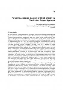
represents a more suitable interface with electronics (and computer-based software) that could be embedded in future aqueous microrobots. This chain of magnetosomes acts like a compass and enables the MTB to orient themselves and to swim along the lines of a magnetic field. This can be controlled by the generation of magnetic field lines using small, programmed electrical currents passing through a special embedded conductor network. By comparison to other traditional methods, relatively large embedded voltage converters are not required. Furthermore, heat generation and electrical power requirements are minimized since electrical current is only used to change the direction of the bacteria and not to induce a force on the MTB. In other words, the motility of MTB is exploited. Hence, in order to achieve the minimum threshold necessary to exert sufficient torque on the chain of magnetosomes while at the same time minimizing the power requirement for each microrobot, the space between the conductors and the MTB embedded in the microrobot must be sufficiently small and becomes a critical issue in the final implementation. To power the embedded electronics, since wires will impact the motion of the microrobot, an untethered implementation based on CMOS photovoltaic cells has been designed. II. CONTROLLED BACTERIAL ACTUATION The electrical power requirement of such microrobots can be minimized by using bacteria as motors for propulsion. Hence, preliminary experiments showing the feasibility of the concept of controlled bacterial actuation has been demonstrated by our group as depicted in Fig. 1. To achieve sufficient thrust to push a relatively large object such as an entire microrobot, several MTB pushing in the same direction will be needed. Fig. 1a shows that an entire swarm of MTB (here of type MC-1) can be controlled to swim in the same direction. In Fig. 1b, an MTB of type Magnetospirillum gryphiswaldense [9] was used to push a microbead in a controlled manner. The experimental results
1335
confirm that MTB could potentially be controlled to operate as micro-actuators to propel future untethered microrobots.
1
2
3
(a) 4 sec 2.5 sec 0 sec
(b) Fig. 1 – (a) Directional control of a swarm of MC-1 magnetotactic bacteria sweeping an aqueous solution at an average speed of 130 µm/s with a total round-trip distance being swept of approximately 1 mm. The black arrows indicate the direction of intended motion. (b) Directional control of a 3micrometer bead being pushed by a single Magnetospirillum gryphiswaldense MTB with an intentional change in the direction of the swimming path occurring after 2.5 seconds.
III. MICROROBOT The untethered microrobot described here is an Autonomous Bacterial System (ABS). Such systems have no external control and do not include the directional control conductor networks usually used to achieve results similar to the ones depicted in Fig. 1. The control scheme is already embedded in each microrobot. ACTUATION SLOT (RESERVOIR) MICROCIRCUIT (PROCESSOR)
SENSORS
MTB
R F B L
CONTROL NETWORK DIRECTION OF INTENDED MOTION
Fig. 2 Simplified diagram of one microrobot (not to scale) with independent right (R), left (L), forward (F), and backward (B) motion control. The overall length of each microrobot is expected to be in the order of a few hundred micrometers. The surface of the microrobot is covered with cells to collect photon energy from environmental light to generate one hundred microamperes of electrical current.
For example, a swarm of ABS each with the same or different pre-programmed behavior could operate in a drop
of aqueous solution on a simple microscope slide. Here, each ABS would interact and work on samples as a collective entity in order to accomplish relatively complex and apparently coordinated tasks in a way similar to that of a colony of ants, and this initially without the need for communication between the ABS and an external system. Our first ABS or microrobot under development (Fig. 2) consists of a microcircuit with embedded minimum programmed specific behavior description. Such microcircuit is capable of generating small magnetic fields through an embedded conductor network to force the MTB that are encapsulated in micro-reservoirs to push in the desired direction. Previous experiments showed that a single magnetotactic bacterium could move a bead of 3 µm, 10 µm, and 100 µm in diameter with a minimum average speed of ~16.3, 4.9, and 0.49 µm-s-1 respectively, corresponding from Stokes' law, to a thrust of ~0.5 pN per bacterium. Furthermore, since the low Reynolds’ number drag also scales like the size of the object, we can expect higher velocities with more MTB attached to the larger structure of the microrobot. Since an increase of the propulsion force is obtained through a larger number of MTB pushing in the same direction, the surface area available becomes critical. More specifically, the total surface available between the structure of the microrobot and the MTB, which is a determining factor of the total pushing force, depends not only on the density of MTB which may vary between ~1 2 2 bacterium/6 µm to ~1 bacterium/2 µm but also depends mainly on the number of reservoirs (acting as “bacterial engines”), the distance between the reservoirs, and the distance between the pushing surfaces within each reservoir. The latter would be influenced by the total depth of fluid affected by the flagella, which may be in the order of 50 µm with a half-depth of approximately 10 µm unless porous walls are being implemented. Ideally, this calls for a multireservoir structure made of porous walls (with holes smaller than the diameter of the bacteria) as depicted in Fig. 2. Interesting is the fact that such an increase of the resulting propulsion force does not necessarily lead to an increase of the electrical current required for controlling the direction of propulsion. This is true if the wiring topology embedded in each microrobot is sufficiently small such as to reach the magnetic field threshold (> 0.1-0.5 Gauss) necessary to affect the direction of motion of the MTB at a distance equivalent to the distance between two neighboring conductors. Although embedding such a control conductor network would allow each microrobot in a swarm to navigate according to an independent path, transmitting enough electrical energy to influence the swimming direction of the MTB (through local magnetic fields created by a very small electrical current flowing through neighbored conductors) is still a non obvious task. The methods for energy transfer
1336
cannot rely on induction since directional control would be lost through the electrical current induced in the control networks. As such, an approach where photovoltaic cells embedded in each microrobot would collect energy from an incident light source has been selected. Nonetheless, due to the very small surface area available on top of each microrobot and the minimum photonic current that must be generated to power the embedded electronics (while generating local magnetic fields sufficient to control the orientation of the MTB), the design of such cells is still quite challenging.
every single space in the given cell surface for photonic conversion is considered. V. THEORETICAL ANALYSIS A radiance that has sufficient energy, i.e. that its energy is greater than the energy band gap of the silicon (∼1.12 eV, see Fig. 3) will force an electron to go from the valence band to the conduction band, thus provoking reactions in the pn silicon junction pairs of electron-holes in the zone of depletion without any immediate recombination due to the presence of the internal electric field Φo being created.
IV. PHOTOVOLTAIC CELLS The fabrication of a photovoltaic cell is primarily based on thin-film and thick-film silicon [10]. These technologies offer good power cell efficiency (∼6%), especially in poor light conditions. There are also mono-crystalline and polycrystalline type photovoltaic cells, with respective efficiencies of approximately 15-20% and 10-14% respectively [10]. The integration of the thin film and the thick film types of photovoltaic cells with a microelectronic Integrated Circuit (IC) is a complicated task since the manufacturing processes are different from the one used for ICs. The development of microelectronic tools allows engineers to build smaller circuits and therefore, the avenue of integrating the power cell on the same electronic die is very promising. However, this idea is not new. It is proven that building a power cell with the standard CMOS technology is possible [11-14] since a photovoltaic cell can be resumed to a simple pn junction. For example, using the standard CMOS process, a 150 V photovoltaic cell has been built in an area as small as 1 cm2 to power electrostatic MEMS. P-Intrinsic-N (PIN) photodiode is not recommended in standard CMOS technology, and resonant cavity photocells cannot be made with that technology [15]. Therefore, a photovoltaic cell based on the CMOS standard technology is a simple photodiode that is an adaptation of a photovoltaic cell. The weakness of the CMOS photovoltaic cell is a consequence of the useful area that is not utilized at its maximum for photonic conversion. Some designs were proposed to optimize this area so that the photovoltaic cells will have a larger useful area for photonic conversion and consequently, will be able to provide more current. An example is the lateral polysilicon photodiode in the standard CMOS technology whose architecture is to increase the useful area of a photodiode [14]. This architecture was proposed for the photodiode and it was implemented and simulated with Cadence tool [17]. The simulation results were satisfactory but they cannot provide the minimum power required for our application. There is still a large unused surface with this proposed lateral polysilicon photodiode architecture. Hence, a new architecture based on CMOS 0.18µ technology, allowing designers to exploit
Holes
Free electrons
n
+ p Φo
Fig. 3 Diode depletion region
The pairs of electron-holes which are outside the diffusion zone recombine in the p and n areas and do not participate in the flow of the external current. Hence, three zones contribute to the generation of the photocurrent, namely, the depletion zone (Idrift), the diffusion zone in the semiconductor p (Idiffp), and the diffusion zone in the semiconductor n (Idiffn). Therefore, the expression of the photonic current is given by
I ph = I diffp + I diffn + I drift
(1)
where
I diffp = qGALp I diffn = qGALn
(2)
I drift = qGAWd Therefore,
I ph = qGA( Lp + Ln + Wd ) .
(3)
The photonic current is proportional to the diffusion length in the p and n semiconductor (Lp,n) and the depletion zone Wd. G is the rate of generation of pairs of electronholes, q is the charge of an electron and A is the useful area for photon conversion into electricity. The useful area is typically smaller than the area of the cell because the electrons will not diffuse on the whole surface of the cell, instead they will diffuse up to a distance called the diffusion length. The diffusion length depends on the life time of the minority-carriers, and therefore on their mobility, which also depends on the doping concentration of the semiconductor. Since for most cases designers cannot change the foundry fabrication process, in this paper, we present a new
1337
architecture to increase the photonic current by increasing the useful area of the photodiode. With the architecture depicted in Fig. 4, the useful area is optimal because more pn junctions have been created on a given area, thus increasing the useful area of the photodiode. Knowing that the electron-holes pairs that are outside the diffusion zone (area) do not participate in the flow of the external current (consequently being useless to go too far away from the junction), a CMOS photovoltaic cell based on concentric squares with an alternate type for n and p-type semiconductor is proposed. First, a square of p-type semiconductor is created followed by a square of type n, thus alternating types with the addition of new squares. This latter pattern allows the formation of pn junctions anywhere on the surface area of the cell, creating more depletion areas and leading to more diffusion and drift currents, composing the resulting photonic current. (b)
(a)
This depletion area can be calculated as
Wd =
Ln, p = Dn, pτ n, p .
p p n Fig. 4 (a) Cross-sectional view of the cell and (b), view of the architecture of the cell from Cadence layout Virtuoso
A. Estimation of the Photonic Current To estimate the photonic current, the value for the depletion width Wd, and the value for the diffusion length in the p and n-type semiconductor which is given by Lp,n must first be evaluated. Let Wn be the depletion region in the ntype semiconductor and Wp the depletion in the p-type semiconductor for one cell, this value will intervene in the determination of the useful area of the cell.
Wd
n+
Wn
p+
Wp
Fig. 5 Useful area of the cell
The depletion area that contributes to the drift current is given by the sum of the p and n-type depletion widths in the semiconductor (Eq. 4).
Wd = Wp + Wn
(4)
(5)
In Eq. 5, NA equals the concentration of acceptor ions, and ND represents the concentration of donor atoms. Both of these variables depend on the manufacturing process. Also in Eq. 5, εs is the permittivity of the silicon, q the electronic charge, Φo is the built-in potential voltage (at noon day its value is 0.6 V for silicon [16]). For CMOS 0.18µ technology, the typical doping concentrations for the p-type and n-type semiconductor are 1015 cm-3 and 5×1015 cm-3 respectively. The two remaining components of the photonic current depend on the diffusion length in the p and n-type semiconductor. The value for the diffusion length also depends on the foundry, but it can be calculated using Eq. 6 [16] by knowing data such as the diffusion constant which depends on the electron-hole mobility being related to the doping concentration level.
n
p-substrat
2ε s NA + ND . Φo q NA ND
(6)
In Eq. 6, Dn,p is the diffusion constant, and τn,p is the life time of the minority-carriers. For CMOS 0.18µ technology, this value is approximately 50 picoseconds (ps) [15]. The calculated values for the depletion width Wd, and the diffusion lengths Ln and Lp are 1.244 µm, 0.4 µm, and 0.245 µm respectively. These values are based on a single cell, and will be amplified with the proposed architecture. Having found these parameters, we need to determine the rate of generation of electron-holes pairs G in order to find the photonic current Iph.
G =α
Pinc , EphotonAcell
(7)
In Eq. 7, α is the absorption coefficient of silicon, and depends on the given wavelength (light source). Pinc in Eq. 7 is the power of the incident radiance, Ephoton is the photonic energy, and Acell is the useful area of the photovoltaic cell. A green light (555 nm wavelength) acting as the incident source on the photovoltaic cell is taken into account to calculate the rate of electron-holes generation. We do not want to choose a longer wavelength, because the time carrier recombination will be slow thus affecting the speed performance of the cell. At the same time we cannot use very short wavelength because a little amount of the incident radiance will be absorbed by the cell. Another reason is that some other wavelengths are prohibited in our application. For instance, wavelengths in the blue region have shown to kill bacteria and hence, cannot be used in this particular application. The proposed cell will generate a 100 µA shortcircuit current. The layout of the cell was made in Cadence tool, in order to perform a simulation. Conventional electronic CAD
1338
tools were used to simulate the photovoltaic cell after the hspice netlist was extracted from Cadence.
I (µA)
Rsh
50 mW / cm2
50 0
0.1
0.2
0.3
0.4
0.5
0.6
- 50 - 100 - 150 Voc(V)
Fig 7. Simulated I-V characteristics of the photocell for different light intensities. I (μA) 100 80
Extracted Cell Ish
100 mW / cm2
100
This circuit was simulated using Cadence layout Virtuoso, and then an Hspice extracted netlist of the design was generated. This file was used to perform the post-layout simulation of the cell. To simulate the photovoltaic cell with Hspice, the generated netlist was modified in order to model the internal photovoltaic cell resistance (Rs), in series with the photodiode and opposing the external flow of the current, and a shunt resistance (Rsh), in parallel with the photodiode. This shunt resistance is the resistance exerted by the semiconductor’s crystal against the internal flow of the current. The circuit model of the photovoltaic cell is depicted in Fig. 6 where a current source is used to model the light intensity.
Rs
150 mW / cm2
150
VI. SIMULATION RESULTS AND DISCUSSION
I
200 mW / cm2
200
60 40
ID
Iph
20 0 0.1
0.2
0.3
0.4
0.5
0.6
Voc (V)
Fig. 8 Simulated I-V characteristics of the photocell for 100 µW/cm2 light intensity.
Fig. 6 Model of the photovoltaic cell
P (μW)
From the above picture, the total output current delivered by the photovoltaic cell is given by I = I ph − I D − I sh , (8)
100 80
Therefore, (V + IRs ) V + IRs , I = I ph − I S expq − 1 − R sh ηKT
60 40
(9)
20
Where in Eq. 8, I is the output current, ID, Ish and Iph respectively the diode current, the shunt current, and the photocurrent, and in Eq. 9, V the cell open voltage, Is the diode saturation current, K the Boltzman constant, T the temperature of the cell, q is the charge of an electron, and η a constant that can take one of two values (1 or 2) depending on the structure of the diode [16]. The value of the shunt resistance can be extracted from Eq. 9 as V + IRs , Rsh = (10) I sh The n+ and the p+ diffusion depths are approximately equal to 0.1 µm, with a sheet resistance respectively of 6.3 and 6.5 Ω/sq, and a contact resistance for n+ and p+ of 7.3 and 8.3 Ω respectively. Various simulations with different values of light intensity have been performed as depicted in Fig. 7.
0
0.1
0.2
0.3
0.4
0.5
0.6
Voc (V)
Fig. 9 Simulated P-V characteristics of the photocell for different light intensities.
We observe in Fig. 7 a shift to the right of the openvoltage with an increase of the light intensity where the cell exhibits an open-voltage of 0.58 V, and a short-circuit current of 100 µA for a light intensity of 100 mW/cm2. This is made obvious in Fig. 8. The cell’s maximum power is estimated at 48.4 µW from Fig. 9 with an incident light power of 100 mW/cm2. From these data, the photovoltaic cell efficiency is estimated at 12.5% with a fill factor computed from Eq. 10 of 79%.
1339
FF=
Pmax Voc I sc
(11)
VII. CONCLUSION The use of a novel micro-actuation method based on magnetotactic bacteria for propelling an untethered aqueous microrobot under the control of an embedded electronic system allows us to minimize the electrical power that must be provided. Here, the design of a photovoltaic cell to capture such energy from an incident light source to control the direction of motion of a microrobot propelled by magnetotactic bacteria has been described. Simulation results at different light intensities have also been presented showing open and short circuit conditions. For maximum efficiency within the constraints of such applications, a source of green light has been selected due to its wavelength. If the wavelength is too short, a large quantity of photons will be reflected instead of being absorbed by the cells, lowering the efficiency. On the other hand, if the wavelength of the incident light source is too long, the reaction time of the cells will be reduced due to the speed of recombination of the minority carriers. The cell has a sheet resistance of 6.3, and 6.5 Ω/sq, and a contact resistance of 7.3 (n+) and 8.3 (p+) Ω. The efficiency of the cells is estimated at 12.5%. Four of these cells embedded in a microrobot with an overall length and width of approximately 400 µm would provide ∼100 µA of photonic current. With a pre-selection of bacteria more sensitive to a directional control from a local magnetic field as low as 0.1 Gauss, such magnitude of photonic current is most likely to be sufficient to control the movement of the microrobot if the bacteria could be maintained within 2 µm from the control conductor where such photonic current flows. On the other hand, without a pre-selection and assuming a worst case threshold of 0.5 Gauss, the distance between the conductor and the magnetotactic bacteria must be maintained below 400 nanometers (nm) if the response of most of the bacteria population is required. With CMOS 0.18µ microfabrication technology limiting the width of the conducting trace to 230 nm, and the same distance separating each pair of traces, efficiency in bacterial actuation may be reduced unless such pre-selection of the most responsive bacteria is performed. ACKNOWLEDGMENT This work was initially fully supported by a grant from the Canadian Institute for Robotics and Intelligent Systems (IRIS). It is presently supported in part by a Canada Research Chair (CRC) in Micro/Nanosystem Development, Fabrication, and Validation, the Canada Foundation for Innovation (CFI), the National Sciences and Engineering Council of Canada (NSERC), and the Government of Québec. The authors acknowledge the help of the members of the NanoRobotics Laboratory and in particular, C. C. Tremblay, S. Ngakeng and G. Langlois for their involvement in the experimental proof of concept of the
controlled bacterial actuation; and B. Moufarrej for software development and Z. Lu for microfluidic devices fabrication necessary to perform experimental tests on the magnetotactic bacteria. The bacteria were provided by D. Schüler from the Max-Planck Institute for Marine Microbiology in Bremen, Germany, and D. A. Bazylinski from the Dept. of Biochemistry, Biophysics and Molecular Biology, Iowa State University. REFERENCES [1] J. Happel and H. Brenner, Low Reynolds number hydrodynamics, Martinus Nijhoff, The Hague, the Netherlands, 1983. [2] H. C. Berg and D. A. Brown, “Chemotaxis in Escherichia coli analyzed by three-dimensional tracking,” Nature, vol. 239, pp. 500504, 1972. [3] R. M. Ford, B. R. Phillips, J. A. Quinn, and D. A. Lauffenburger, “Measurement of bacterial random motility and chemotaxis coefficients. I. Stopped-flow diffusion chamber assay,” Biotech. and Bioeng., vol. 37(7), pp. 647-660, 1991. [4] J. P. Armitage, “Bacterial motility and chemotaxis,” Sci. Progr., vol. 76, pp. 451-477, 1992. [5] R. P. Blackmore, “Magnetotactic bacteria,” Science, vol. 190, pp. 377379, 1975. [6] R. B. Frankel and R. P. Blakemore, “Navigational compass in magnetic bacteria,” J. of Magn. and Magn. Materials, vol. 15-18 (Part 3), pp. 1562-1564, 1980. [7] C. Denham, R. Blakemore, and R. Frankel, “Bulk magnetic properties of magnetotactic bacteria,” IEEE Trans. on Magnetics, vol. 16(5), pp. 1006-1007, 1980. [8] H. Debarros, D. M. S. Esquivel, and M. Farina, “Magnetotaxis,” Sci. Progr., vol. 74, pp. 347-359, 1990. [9] K. H. Schleifer, et al., “The genus Magnetospirillum, description of Magnetospirillum gryphiswaldense and transfer of Aquaspirillum magnetotacticum to Magnetospirillum magnetotacticum,” Syst. Appl. Microbiol., vol. 14, pp. 379-385, 1991. [10] O. Mah, “Fundamentals of Photovoltaic Materials”, Nantional solar power research institute, Inc (NSPRI), 1998 [11] S. Hollar, A. Flynn, C. Bellew, and K. S. J. Pister, “Solar powered 10 mg silicon robot,” Proc. of the IEEE Micro Electro Mechanical Systems (MEMS), pp. 706-711, 2003 [12] C. L. Bellew, S. Hollar, and K. S. J. Pister, “An SOI process for fabrication of solar cells transistors and electrostatic actuator,” 12th Int. Conf. on Solid-State Sensors, Actuators and Microsystems (TRANSDUCERS '03) - Digest of technical papers, vol. 2(2), pp. 1075-1078, 2003. [13] B. A. Warnet, M. D. Scott, B.S. Leibiwitz, L. Zhou, C. L. Bellew, C. J. Chediak, J. M. Kahn, B. E. Boser, and K. S. J. Pister, “An autonomous 16 mm3 solar-powered node for distributed wireless sensor networks,” Proc. of IEEE Sensors 200 - First IEEE Int. Conf. on Sensors, vol. 2(2), pp. 1510-15, 2003. [14] S. Radomanovic, A. J. Annoma, and B. Nauta, “High speed lateral polysilicon photodiode in standard CMOS technology,” Proc. of the 33rd European Solid-State Device Research (ESSDERC '03), pp. 521524, 2003. [15] CMOS 0.18 Design Rules: http://www.mosis.com [16] A. S. Sedra and K. C. Smith, “Microelectronic circuits,” Oxford series in electrical and computer engineering, 5th ed., pp. 150-210, 2004. [17] T. N. Swe and K. S. Yeo, “An Accurate photodiode model for DC and high frequency SPICE circuit simulation,” Int. Conf. on Modeling and Simulation of Microsystems (MSM 2001), pp. 362-365, 2001.
1340