Design of Preamble Signal for Synchronization in UWB Non-coherent Energy Detection Receiver Sung-Yoon Jung and Dong-Jo Park Department of Electrical Engineering and Computer Science Korea Advanced Institute of Science and Technology (KAIST) 373-1 Guseong-dong, Yuseong-gu, Daejeon, Republic of Korea 305-701 E-mail:
[email protected] and
[email protected]
Abstract— In this paper, we deal with the design of preamble signal in order to increase synchronization performance in UWB non-coherent energy detection receiver. We find criteria which can enhance the synchronization performance and propose a scheme to design the preamble signal based on the constrained nonlinear optimization approach with some examples. The proposed design scheme provides the improved solution for designing preambles in non-coherent energy detection based synchronization. Through simulations, we shows the synchronization performance of designed preamble signals in AWGN and the IEEE 802.15.3a channel model.
I. I NTRODUCTION The ultra-wideband (UWB) communication system is known as a carrierless (base-band) radio system. Therefore, the analog front-end complexity is quite lower than that of the traditional carrier based radio system. This makes it possible to design very low complexity, low power consumption and low cost devices. Therefore, it is considered as a candidate in the 802.15.4a low data rate wireless personal area network (W-PAN) standardization [1]. The purpose of this standard is to support higher precision ranging/location capability (1 meter accuracy and better) with low power consumption and cost than the existing 802.15.4 standard known as ZigBee. Also, low data rate sensor networks, which provide location and tracking services, are a good application for adopting the UWB communication system. It is well known that the UWB signal provides very high spatial resolution thanks to its ultra-large bandwidth. Nevertheless, it results in substantial increase in system complexity to generate timing information from the time domain UWB signal. A classical RAKE receiver leads to high receiver complexity due to the large number of fingers required to collect energy from the harsh multipath channel. In addition, a high speed and precision clock may be required. However, the devices used for low data rate sensor networks or W-PAN require the low hardware complexity. A non-coherent energy detection receiver can produce a low complexity, low cost and low power consumption solution at the cost of reduced channel spectral efficiency. Recently, noncoherent energy detection receivers for UWB are reported [2], [3]. Especially, synchronization process based on the non-coherent energy detection receiver, which can minimize the complexity of the receiver using a short preamble, is introduced in [4]. For synchronization, the energy detection
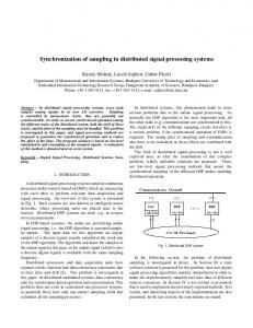
receiver simply collects the preamble signal energy in a different time window at the receiver and determines the synchronization point based on the detected maximum energy. In this paper, we deal with the design of preamble signal in order to improve synchronization performance in the noncoherent energy detection receiver. We find criteria which can enhance the synchronization performance and propose a scheme to design the preamble signal based on the constrained nonlinear optimization approach with some examples. We believe that the proposed design scheme provides the improved solution for designing preambles in non-coherent energydetection-based synchronization. The synchronization performance of designed preamble signals is verified in AWGN and the IEEE 802.15.3a channel. II. S YSTEM D ESCRIPTION We develop a system model to design the preamble signal for synchronization based on a low-complexity non-coherent energy detection receiver. A. Preamble Signal Structure Figure 1 shows the basic structure of the preamble signal.
Fig. 1.
The basic structure of the preamble signal
The preamble is composed of the signaling part s(t) followed by the guard interval which possesses the same time duration with s(t). The signaling part is represented by s(t) =
NX s −1
pi (t − iTp )
(1)
i=0
where pi (t) means the i-th pulse with pulse bin width Tp s and energy Epi . {pi (t)}N i=0 are parameters to be designed s for synchronization. The detail of designing {pi (t)}N i=0 will be discussed in Section III. The time duration and energy of the signaling part which contains PNs −1 total Ns basic pulses will be Ts = Ns Tp and Es = i=0 Epi , respectively. And the total time duration of the basic preamble signal is Tb = 2Ts .
If we let the basic preamble signal be transmitted N times for reliable synchronization, the transmitted preamble signal is given as N −1 X x(t) = s(t − nTb ). (2) n=0
B. Received Preamble Signal The received preamble r(t) over the UWB multipath channel is r(t) = x(t) ? h(t) + n(t) (3) where n(t) is additive white gaussian noise (AWGN) and ? stands for the convolution operator. h(t) is the channel impulse response which is modelled by [5] h(t) =
L1 X L2 X
αi,j δ(t − Ti − τi,j )
Fig. 3.
The procedure of synchronization
starting point. After that, the n-th integrator output at the end of the preamble has the value
(4)
Zk =
i=0 j=0
N −2 X
zk,n ,
k = 1, · · · , Nint
(5)
n=0
where {αi,j } are the multipath gain coefficients, {Ti } is the delay of the i-th cluster, {τi,j } is the delay of the j-th multipath component relative to the i-th cluster arrival time (Ti ). This time dispersive effect of the UWB multipath channel plays a fundamental role on the performance of the energy detection based synchronization.
where
Z
ts,k +nTb
2 (t)dt rB
tˆsync = ts + (k ∗ − 1)Tb /Nint
(7)
k ∗ = arg max(Zk ).
(8)
where k
Fig. 2.
The receiver structure
After a band pass filter, detection is performed based on a non-coherent energy detection scheme. The “Square-law device and Integrator,” shown in Fig. 2, do not require the template signal generator and timing-control block which occupy significant portions of the receiver complexity. Therefore, the low-complexity implementation of the receiver is possible with the non-coherent energy detection approach. D. Synchronization Procedure In order to maintain the low complexity nature of the receiver, the synchronization structure should be also based on the energy detection approach. The basic procedure of synchronization is to perform parallel search and then select the maximum output [4]. For synchronization, Nint parallel integrators are used. Each integrator has an integration window of Ts . The procedure of synchronization is shown in Fig. 3. As seen in Fig. 3, the basic preamble signal period Tb is divided into Nint time slots, in which each time slot occupies Tb /Nint time. Then, the starting point of the n-th integrator is ts,k = ts + (k − 1)Tb /Nint where ts is the synchronization
(6)
and rB (t) means the band pass filtered received signal. Then, the estimated synchronization point is
C. Receiver Structure To better understand the synchronization strategy, the receiver structure is presented in Fig. 2.
ts,k +nTb +Ts
zk,n =
The time accuracy of the synchronization procedure is related to the number of integrators. With a bank of Nint integrators in an AWGN channel, the approach can achieve synchronization, tˆsync , to within −
Ts Ts + tsync < tˆsync < tsync + Nint Nint
(9)
where tsync denotes the exact synchronization point. III. D ESIGN OF P REAMBLE S IGNAL The synchronization starting point can be any point within [0, Tb ]. Without the loss of generality, we can choose the starting point within [0, Tb /Nint ]. Then, the synchronization is correct if the output of the first integrator Z1 is greater than the int other integrator outputs {Zk }N k=2 . And, we can easily thnik that the synchronization performance will be the best (ideal case) if ½ (N − 1)Es , k = 1 Zk = . (10) 0, k = 2, · · · , Nint Therefore, our objective is how to design the preamble signal that resembles the ideal integrator outputs in (10) as close as possible.
A. Problem Formulation
C. Methods for Allocating Energy to Pulses
To formulate the preamble design process, let us assume followings. • ts = 0, N = 2. • Ideal channel and no additive noise, (rB (t) = x(t)). • The period of each time slot Tb /Nint is a multiple of Tp , (Tb /Nint = mTp , m : integer). • Ts is a multiple of the period of each time slot, (Ts /mTp = l, l : integer). From the above, we can easily induce that Ns = ml and Nint = 2l. Let Z = [Zl+1 , · · · , ZNint , Z1 , · · · , Zl ]T denote the integrator output vector that contains the value represented in (5) as each element. Then, we can represent Z as following:
Based on (14), we have to decide the pattern of each pi (t) which possesses the allocated energy Ep∗i . There are many kinds of methods to allocate energy to pulses. In this paper, we allocate the energy to each pi (t) by varying the amplitude and length of the pulse. We leave other kinds of pulse energy allocation methods as future work.
Z = WTy
(11)
where W is a 3l × Nint Toeplitz matrix with the first column [1Tl×1 , 0T2l×1 ]T ; and y = [0Tl×1 , y1 , · · · , yl , 0Tl×1 ]T with Z ts +jTb /Nint yj = x2 (t)dt =
ts +(j−1)Tb /Nint jm−1 X Z p2i (t)dt i=(j−1)m ∈Tp
jm−1 X
=
(12) Epi .
B. Optimal Energy Allocation of Pulses Let t = [0Tl×1 , Es , 0T(2l−1)×1 ]T denote the ideal output values we want to resemble. Then, we can formulate the constrained nonlinear optimization problem as follows: min f (y) = kt − W T yk2 s.t. 0 ≤ l X
≤ m · Ep (13)
yj = Es
j=1
where Ep means the energy constraint of each pi (t) which has the range 0 ≤ Epi ≤ Ep ≤ Es . This constraint prevents the allocated energy to each pulse from being preponderated. To solve the above nonlinear optimization problem, we used a sequential quadratic programming (SQP) method. In this method, the function solves a quadratic programming (QP) subproblem at each iteration. An estimate of the Hessian of the Lagrangian is updated at each iteration using the BFGS formula [6], [7]. After finding the optimal y ∗ from (13), the energy allocated to each pi (t) is calculated as Ep∗i =
1 ∗ y . m bi/mc+1
a
2) Energy Allocation Based on Pulse Length: In pulse length method, each pi (t) is given as N∗
pi (t) =
pi X
wl (t − nTwl ).
(16)
n=0
Here, wl (t) denotes the basic pulse with duration Twl and R 2 w (t)dt = Ewl . And Np∗i = Ep∗i /Ewl (0 ≤ Np∗i ≤ Np ) ∈Twl l with Np = Ep /Ewl = Tp /Twl . D. Examples
i=(j−1)m
Now, the problem of designing preamble signal is turned to how to allocate the preamble energy Es to each pi (t) and R design pi (t) satisfying ∈Tp p2i (t) = Epi in order to make each element of Z resemble the ideal output values represented in (10) as close as possible.
{yj }lj=1
1) Energy Allocation Based on Pulse Amplitude: By using the energy allocation method based on pulse amplitude, each pi (t) is represented by q pi (t) = Ep∗i wa (t) (15) R where wa (t) is a basic pulse with ∈Tw wa2 (t)dt = 1.
(14)
In this subsection, we will provide two examples of designing a preamble signal. As basic pulses wa (t) and wl (t), we used the doublet of the prolate pulse [8] of time duration Twl = 4.28 ns. One prolate pulse possesses bandwidth of approximately 2 GHz, a center frequency of 4 GHz, and time duration of about 2.14 ns. Other design parameters needed for synchronization are described in Table I. TABLE I PARAMETERS FOR D ESIGNING P REAMBLE S IGNAL
Ns Nint Ep Np (m, l) Tp Ts Tb
Example 1 10 10 Es /Ns 2 (2, 5) 8.56 ns 85.6 ns 171.2 ns
Example 2 10 10 2Es /Ns 2 (2, 5) 8.56 ns 85.6 ns 171.2 ns
Figure 4 shows the allocated energy to each pi (t) and Fig. 5 represents the corresponding output values of integrators. We can see from figures that non-uniform energy allocation to each pi (t) results in integrator outputs which are more close to the ideal integrator outputs in (10). Therefore, we can think that the synchronization performance of Example 2 is expected to be better than Example 1. Figure 6 and 7 show shapes of the signaling part s(t) of the preamble signal based on pulse amplitude and length methods. Note that the design results corresponding to Example 1 show the same preamble pattern used in [4].
0.2
x Es
0.2
0.25
0.2
x Es
0.2 0.15
0.18
0.14
0.12
0.1
0.08
0.06
0.04
0.15 0.16
0.1 0.1
0.14
0.12
0.1
0.05
0
−0.1 −0.15
0.04
−0.15 0.02
0
−0.2 3
4
5
6
7
8
9
10
1
2
3
4
(a) Example 1
6
7
8
9
1
2
3
10
4
5
6
7
8
9
1
2
3
4
5
6
7
8
9 −8
x 10
Time
x 10
(a) Example 1
(b) Example 2
Fig. 6. The shape of the signaling part s(t) of the preamble signal based on pulse amplitude method.
The allocated energy to each pulse pi (t).
x Es
x Es
1
0.9
0.8
0.8
0.7
0.7
0.5
0.4
0.6
0.5
Amplitude
0.6
0.4
0.2
0.2
0.15
0.15
0.1
0.1
0.05
0.05
Amplitude
0.9
0
−0.05
0
−0.05
0.3
0.3
0.2
0.2
−0.1
−0.1
0.1
0.1
−0.15
−0.15
0 6
0
−8
Time
(b) Example 2
Collected Energy, Zk
Collected Energy, Zk
1
5
−0.2
−0.25 0
Pulse−unit Index
Pulse−unit Index
Fig. 4.
0
−0.05
−0.1 0.06
0
2
0.05
−0.05
0.08
0.02
1
Amplitude
0.16
Amplitude
Allocated Energy to Each Pulse−unit, Epi
Allocated Energy to Each Pulse−unit, Epi
0.18
7
8
9
10
1
2
3
Square−law Integrator Index
(a) Example 1 Fig. 5.
4
5
0 6
7
8
9
10
1
2
3
4
5
−0.2
Square−law Integrator Index
1
2
3
4
5
Time
(b) Example 2
The output value of each integrator, Zk .
0
6
7
8
9 −8
−0.2
0
1
x 10
(a) Example 1
2
3
4
5
6
Time
7
8
9 −8
x 10
(b) Example 2
Fig. 7. The shape of the signaling part s(t) of the preamble signal based on pulse length method.
IV. S IMULATION R ESULTS Through simulations, we investigate the synchronization performance of two designed preamble signals. As a performance measure, we consider the probability of synchronization which means the probability that detect the nearest possible synchronization point within the time accuracy defined in (9). Simulation are performed by using examples of the designed preamble signal described in Section III. The number of repetition of the basic preamble signal is set to 10, (N = 10) and we use AWGN and CM2 [5] as channel model. In the case of CM2, the channel is randomly selected from 100 channel realizations at each run. Total 10, 000 Monte-carlo runs are performed for performance evaluation. The time accuracy of synchronization for each example is shown in Table II. TABLE II T IME ACCURACY OF S YNCHRONIZATION OF D ESIGNED P REAMBLE ¡ ¢ S IGNALS (−x, y) := −x + tsync < tˆsync < tsync + y
Example 1 Example 2
Time Accuracy (−8.56 ns, 8.56 ns) (−8.56 ns, 8.56 ns)
•
•
•
In both methods, as might have been expected, the synchronization performance of Example 2 is better than that of Example 1 in both methods. This is because the int output values of the integrator {Zk }N k=1 of Example 2 is more close to the ideal integrator output values in (10) than those of Example 1. In the case of CM2, the performance gap between Example 1 and Example 2 is wider than the AWGN case in both methods. Therefore, we can say that Example 2 is more robust to multipath interference than Example 1. In the case of Example 2, the synchronization performance of the preamble signal based on the pulse amplitude method is a little bit better than the pulse length method in CM2. This is because the time dispersive effect of the channel is larger in the case of the pulse length method than the pulse amplitude method. However, in the practical implementation, the preamble signal based on the pulse amplitude method may suffer from the distortion in its amplitude due to the non-linear characteristic of the amplifier. V. C ONCLUSION
Figures 8 and 9 shows the probability of synchronization based on the pulse amplitude and length methods. From figures, we can obtain the following results.
In this paper, we proposed design of preamble signal in order to increase synchronization performance in the UWB non-coherent energy detection receiver. By using a constrained
1
nonlinear optimization approach, we proposed a scheme to design preamble signal such as pulse amplitude and length methods. The proposed design scheme provides the improved solution for designing preambles in non-coherent energy-detectionbased synchronization. Through simulations, we showed the synchronization performance of designed preamble signals in the AWGN and IEEE 802.15.3a channel model 2.
0.75
0.7
Synchronization Probability
Synchronization Probability
0.9
0.8
0.7
0.6
0.5
0.65
0.6
0.55
0.5
0.45
0.4
0.35
0.4
Example 1 Example 2 0.3 −20
−15
−10
−5
0
5
Example 1 Example 2
0.3
0.25 −20
10
−15
−10
SNR (dB)
−5
0
5
10
SNR (dB)
(a) AWGN
(b) CM2
Fig. 8. The probability of synchronization based on pulse amplitude method.
1
0.75
0.7
Synchronization Probability
Synchronization Probability
0.9
0.8
0.7
0.6
0.5
0.65
0.6
0.55
0.5
0.45
0.4
0.35
0.4
Example 1 Example 2 0.3 −20
−15
−10
−5
SNR (dB)
(a) AWGN Fig. 9.
0
5
Example 1 Example 2
0.3
10
0.25 −20
−15
−10
−5
0
5
10
SNR (dB)
(b) CM2
The probability of synchronization based on pulse length method.
R EFERENCES [1] http://www.ieee802.org/15/pub/TG4a.html [2] M. Weisenhorn and W. Hirt, “Robust noncoherent receiver exploiting UWB channel properties,” Proc. Joint UWBST & IWUWBS 2004, Kyoto, Japan, pp. 156-160, May 18-21, 2004. [3] M. K. Oh and D. J. Park, “A new noncoherent UWB impulse radio receiver,” IEEE Comm. Letters, vol. 9, pp. 151-153, Feb. 2005. [4] A. Rabbachin and I. Oppermann, “Synchronization analysis for UWB systems with a low-complexity energy collection receiver,” Proc. Joint UWBST & IWUWBS 2004, Kyoto, Japan, pp. 288-292, May 18-21, 2004. [5] “Channel modeling sub-committee report final,” IEEE P802. 15wg for WPANs, Feb. 2003. [6] R. Fletcher and M. J. D. Powell, “A rapidly convergent descent method for minimization,” Computer Journal, vol. 6, pp. 163-168, 1963. [7] D. Goldfarb, “A family of variable metric updates derived by variational means,” Mathematics of Computing, vol. 24, pp. 23-26, 1970. [8] B. Parr, B. L. Cho, K. Wallace and Z. Ding, “A novel ultra-wideband pulse design algorithm,” IEEE Comm. Letters, vol. 7, pp. 219-221, May 2003.