Al-Mansour University College Civil Engineering Department
DESIGN OF REINFORCED CONCRETE SLABS BY SAFE PROGRAM A Final Year Project Submitted to the Department Of Civil Engineering at Al-Mansour University College in Partial Fulfillment of the Requirements For the Degree Of BS.C in Civil Engineering. By 1-Ibrahem Thamer 2-Hairth Muthana 3-Assra Ali 4-Hawraa Alaaaldeen
Supervised by Dr. Ola Adel Qasim A.D 2016
A.H 1437
Abstract
Abstract
ABSTRACT Slabs are the flooring systems of most structures including office, commercial and residential buildings, bridges, sports stadiums and other facilities building. The main functions of slabs are generally to carry gravity forces, such as loads from human weight, goods and furniture, vehicles and so on. In modern structure design particularly for high rise buildings and basement structures, slabs as floor diaphragms help in resisting external lateral actions such as wind, earthquake and lateral earth load. The slab directly rests on beams or the column and load from the slab is directly transferred to the beams and columns and then to the foundation. To support heavy loads the thickness of slab near the support with the column is increased and these are called drops, or columns are generally provided with enlarged heads called column heads or capitals. Absence of beam gives a plain ceiling, thus giving better architectural appearance than in usual cases where beams are used. Designing of slabs depends upon whether it is a one-way or a two way slab, the end conditions and the loading. The design process of structural planning and design requires not only imagination and conceptual thinking but also sound knowledge of science of structural engineering besides the knowledge of practical aspects, such as recent design codes, bye laws, backed up by ample experience, intuition and judgment. The purpose of standards is to ensure and enhance the safety, keeping careful balance between economy and safety. Safe Program has a very interactive user interface which allows the user to draw the frame and input the load values dimensions and materials properties. Then according to the specified criteria assigned it analysis the structure and design the members with reinforcement details for reinforced concrete frames. The principle objective of this project is to analyze and design different slabs, beams, and columns using (Safe) program according to ACI Code. In order to design them, it is important to first obtain the plan of the particular building that is, positioning of the particular slab. There are many different methods for analysis of two-way reinforced concrete slabs. The most efficient methods depend on using certain factors given in different codes of reinforced concrete design which depend on coefficients taken from special Design of Reinforced Concrete Slabs by Safe Program
I
Abstract
tables available in codes. The other ways of analysis of two-way slabs are the direct design method and the equivalent frame method. But these methods usually need a long time for analysis of the slabs. These methods are approximate but practical and were formed in such a way that the moments are conservative because these methods neglected many important factors to obtain positive and negative bending moments by simple and fast way without complexity. The high accuracy in design calculations of structures is undesirable because there is no capability of estimating many factors affecting on design results such as live loads, material properties and methods of analysis and many other factors. In this research, a new program has been used to analyze the two-way slabs which is (safe), and the results of moments of final analysis of some examples have been compared with other different methods moments given in codes of practice. The comparison proof that this simple program gives good results and it can be used in analysis of two-way slabs instead of other methods. Different types of reinforced concrete slabs were choosing with different number of floors divisions, and analyzed by (Method II, direct design method and safe). A comparison between reinforcement depend on code methods and reinforcement details from safe program which shows that the safe program gives faster and a full map reinforcement details instead of losing time in the drawings. An excel programs were designed to calculate the moments in slabs with interpolations to factors.
This study is divided into Six chapters: The first chapter presents the introduction and types of slabs. The second chapter contains method of design of slabs. The third chapter presents the drawing of slabs and the design and analysis of slabs by Method II with Safe Program. The forth chapter presents the design and analysis of slabs by Direct Design Method. The fifth chapter presents the Comparison of Method II with Direct design and program. The Six chapters present the conclusions and recommendations of this study. Design of Reinforced Concrete Slabs by Safe Program
II
Supervisor Certification
I certify that this project entitled (DESIGN OF REINFORCED CONCRETE SLABS BY SAFE PROGRAM) was prepared under my supervision in Al-Mansour University College as partial fulfillment of requirement for the degree of B.Sc in Civil Engineering.
Signature: Supervisor Name: Dr. Ola Adel Qasim Date:
/
/2016
Committe Certification
We certify that we have read this project entitled (DESIGN OF REINFORCED CONCRETE SLABS BY SAFE PROGRAM) and, we as the examming committee examined the students in its content and they did all the change we required and in our opinion it meets the standard of project for the degree of B.Sc in Civil Engineering.
Signature:
Signature:
Name:
Name:
Date:
/
/2016 (Chairman)
Signature: Name: Dr. Date:
/
/2016 (Supervisor)
Date:
/
/2016
(Member)
Contents
List of Contents SUBJECT Acknowledgment. Abstract. List of Contents. List of Symbols List of Tables. List of Figures.
PAGE NO. I III V VI VIII
Chapter One: Introduction 1-1Types of Slabs. 1-2 Choice Of Type Of Slab Floor. 1-3 Types of RCC Slabs. 1-3-1 Flat Plate System. 1-3-2 Ribbed and waffle slabs System. 1-3-3 Flat slabs. 1-3-4 One-way slabs. 1-3-5 Two-way slabs. 1-4 What is the basic difference between a slab and beam. 1-5 Openings in Slabs. 1-6 Types of Beam. 1-7 Column. 1-8 SAFE System. 1-8-1 The program deals in general with the following structural elements. 1-8-2 Safe used the following codes in design. 1-8-3 Input/Output Graphical Displays. 1-9 Design for ACI 318-08. 1-9-1 Design Load Combinations. 1-9-2 Limits on Material Strength. 1-9-3 Strength Reduction Factors. 1-9-4 Beam Design. 1-9-5 Design Flexural Reinforcement. 1-9-6 Determine Factored Moments. 1-9-7 Determine Required Flexural Reinforcement. 1-9-8 Slab Design. 1-9-9 Design for Flexure. 1-9-10 Determine Factored Moments for the Strip. 1-9-11 Design Flexural Reinforcement for the Strip. 1-9-12 Minimum and Maximum Slab Reinforcement. 1-9-13 Check for Punching Shear. 1-10 Scope of Work.
1 1 2 3 3 4 5 6 7 8 8 9 9 10 11 11 12 12 12 12 12 12 12 13 13 13 13 14 14 14 14
Chapter Two: Method of Design and analysis. 2-1 Analysis of Slabs. 2-2 ACI- Moment Coefficient for Two-Way Slab. Design of Reinforced Concrete Slabs by Safe Program
15 15 III
2-3 Direct design method (DDM). 2-4 Depth Limitations. 2-4-1 Slabs without Interior Beams. 2-4-2 Slabs with Interior Beams. 2-5 Distribution of Moments in Slabs.
16 18 18 20 20
Chapter Three: Design and Analysis of Slabs by Program and Method II. 3-1 Slab (work 1) CSI SAFE-Analysis and Design of Slab with interior Beams. 3-1-1 Prosperities and Descriptions of Slabs. 3-2 Slab (work 2) CSI SAFE-Analysis and Design of Slab with Beam. 3-2-1 Prosperities and Descriptions of Slabs.
24 24 36 36
Chapter Four: Design and Analysis of Slabs by Program and Direct Design Methods. 4-1 Types of Slabs and method of Calculations (direct design method). 4-1-1 Direct design Method (D.D.M). 4-1-2 Determination of two way slab thickness. 4-1-3 Estimating dimensions of Interior and Exterior Beams Sections. 4-1-4 Design Procedure. 4-1-5 Analysis of Slabs by Direct Design Method. 4-2 Slab (work 3) CSI SAFE-04-Analysis and Design of Slab without Interior Beam by Direct Design Method. 4-2-1 Prosperities and Descriptions of Slabs. 4-3 Slab (work 4) CSI SAFE-04-Analysis and Design of Slab without Interior Beam by Direct Design Method. 4-3-1 Prosperities and Descriptions of Slabs. 4-4 Slab (work 5) CSI SAFE-02-Analysis and Design of Slab with Beam. 4-4-1 Prosperities and Descriptions of Slabs. 4-5 Slab (work 6) CSI SAFE-04-Analysis and Design of Slab with Interior Beam by Direct Design Method. 4-6 Slab (work 7) CSI SAFE-04-Analysis and Design of Slab with Interior Beam by Direct Design Method.
41 42 42 43 43 46 46 46 52 52 56 56 63 69
Chapter Five: Comparison of Method II with Direct design & (SAFE) program. 5-1 Slab (work 8) CSI SAFE-Analysis and Design of Slab with Beam. 5-2 Prosperities and Descriptions of Slabs. 5-3 Analysis by using ACI 318M Method II. 5-4 Slab (work 9) CSI SAFE Analysis and Design of Slab.
73 73 75 78
Chapter Six: Conclusions and Recommendations. 6-1 Conclusions. 6-2 From compare the results between hands calculate and the program we find that. 6-3 Recommendations
85 86 86
References
Design of Reinforced Concrete Slabs by Safe Program
IV
List of Symbols Symbols A Ec Es L fc’ fy I hf (𝑦̅) Ib IS
∝𝑓
ln β 𝑀0 𝑙. 𝑙 D.l 𝑊𝑢 𝑉𝑢@𝑑 ∅𝑉𝑐 L 𝑙2 𝑙1 −𝑣𝑒 𝑀 𝑖𝑛𝑡 +𝑣𝑒 𝑀 −𝑣𝑒 𝑀 𝑐. 𝑠 +𝑣𝑒 𝑀 𝑚𝑖𝑑𝑑𝑙𝑒. 𝑠 b d
Definitions
Units
Cross Section area of reinforcement Modulus of elasticity of concrete, psi Modulus of elasticity of reinforcement Span length Ultimate compressive strength of concrete as Determined by cylinder at age of 28 days The yield stress of steel Moment of inertia Thickness of slab Distance from the top of the beam to it neutral axis The moment of inertia for the beams The moment of inertia of the gross section of the slab taken about the centroid axis and equal to h3/12 limes the slab width, where the width is the same as for α.
mm2 Mpa Mpa m, mm
Represent the ratio of the flexural stiffness (EcbIb) of a beam section to the flexural stiffness of the slab (EcsIs) whose width equals the distance between the centerlines of the panels on each side of the beam. The clear span in the long direction, measured face to face, of beams. The ratio of the long to the short clear span. Total moment applied on the frame Live load Dead load Ultimate factored load Shear force came from 𝑊𝑢 acting at distance=d on the slab from beam face Factored concert shear strength The largest distance carry the load 𝑊𝑢 to make maximum shear 𝑉𝑢@𝑑 Transfers length of span c/c Longitudinal length span c/c Negative moment Positive moment Negative moment of column stripe Positive moment of middle strip Width of section, in Distance from compression face to tension reinforcement, in
Design of Reinforced Concrete Slabs by Safe Program
Mpa Mpa mm4 mm mm mm4 mm4
Unit less
mm dimension less kN.m kN.m kN.m kN.m kN kN m
m ,mm m, mm kN.m kN.m kN.m kN.m m, mm m, mm V
List of Tables Table No.
Subject
PAGE NO.
Chapter Two: Method of Design and analysis. (2-1) (2-2) (2-3) (2-4)
Coefficients of Method II. Table 9.5 (c): Minimum thickness of slabs without interior beams. Distribution factors applied to static moment Mo for positive and negative moments in end span. Column strip factored moments.
16 18 22 23
Chapter Three: Design and Analysis of Slabs by Program and Method II. (3-1) (3-2) (3-3) (3-4) (3-5) (3-6) (3-7) (3-8) (3-9) (3-10)
Geometry and Descriptions of Slabs, Beam and Column. Concrete and steel Prosperities of slabs, beam and column. Loads Types and Calculations. Calculation of Moments for all slabs. Comparison of moment by method II and Safe. Geometry and descriptions of slabs, beam and column. Concrete Prosperities of slabs, beam and column. Loads Types and Calculations. Calculation of Moments for all slabs. Comparison of moment by method II and Safe.
24 24 24 25 36 36 37 37 39 40
Chapter Four: Design and Analysis of Slabs by Program and Direct Design Methods. (4-1) (4-2) (4-3) (4-4) (4-5) (4-6) (4-7) (4-8) (4-9) (4-10) (4-11) (4-12) (4-13) (4-14) (4-15) (4-16) (4-17)
minimum thickness of slabs without interior beams. distribution of total static moment in end spans. column strip factored moments. Geometry and descriptions of slabs, beam and column. Concrete and Steel Prosperities of slabs, beam and column. Loads Types and Calculations. Calculation of Moments for all slabs. Comparison of Moments for Strip (B). Comparison of Moments for Strip (C). Calculation of Moments for all slabs. Comparison of Moments for Strip (A). Calculation of Moments for all slabs. Comparison of Moments for Strip (A). Calculation of Moments for all slabs. Comparison of Moments for Strip (A). Calculation of Moments for all slabs. Comparison of Moments for Strip (A).
43 44 46 46 47 47 49 50 51 55 55 62 62 68 68 71 72
Chapter Five: Comparison of Method II with Direct design & (SAFE) program. (5-1) (5-2) (5-3) (5-4)
Geometry and descriptions of slabs, beam and column. Concrete and steel Prosperities of slabs, beam and column. Loads Types and Calculations. Interpolation Program for Solving Coefficients of Method II.
Design of Reinforced Concrete Slabs by Safe Program
73 73 73 74 VI
(5-5) (5-6) (5-7) (5-8)
Calculation of Moments for all slabs. Calculation of Moments for all slabs. Calculation of Moments for Strip A by direct design method. Calculation of Moments by direct design method.
Design of Reinforced Concrete Slabs by Safe Program
75 76 76 79
VII
List of Figures Figure No. Chapter One: Introduction (1-1) (1-2) (1-3) (1-4) (1-5) (1-6) (1-7) (1-8) (1-9) (1-10) (1-11)
Subject
Multi story building Flat plate system Ribbed and waffle system Flat slabs system One way slabs system Two way slabs system Slabs beam system Opening in slabs Common type of beams Exterior and interior column. Safe program
PAGE NO. 1 3 4 5 5 6 8 8 9 9 11
Chapter Two: Method of Design and analysis. (2-1) (2-2) (2-3) (2-4) (2-5)
Column strip for slab design by Direct design method. Examples of the portion of slab to be included with we beam under 13.2.4 Distribution of total static moment to critical section for positive and negative bending Final distribution of moments Torsional cross sectional dimensions for βt calculations.
18 19 21 22 23
Chapter Three: Design and Analysis of Slabs by Program and Method II. (3-1) (3-2) (3-3) (3-4) (3-5) (3-6) (3-7) (3-8) (3-9) (3-10) (3-11) (3-12) (3-13)
3*3 span slab. Multi story (3*3 span slab). Program definition for design of slabs. Entry of slab shape and size. Entry of slab and beam and column properties. Entry of load types and factors. Deformation shape of slab. Results of program (slab forces, beam forces, axial force, stresses, moment, shear, reactions and punching shear). Results of program (slab moment, strip moment if short and long direction). Results of program (slab design and reinforcement). 3*3 span slab and strip position. Results of program (slab moment, strip moment if short and long direction). Deformation shape of slab.
25 26 27 28 29 30 31 33 34 35 37 38 39
Chapter Four: Design and Analysis of Slabs by Program and Direct Design Methods. (4-1) Type of two way slabs and method of design (4-2) Multi span slab (4-3) Effective beam section (a-interior beam, b-exterior beam). (4-4) Moment distribution. (4-5) Full map for building by safe program (4-6) Full map for building by Auto-cad program Design of Reinforced Concrete Slabs by Safe Program
41 41 43 44 47 48 VIII
(4-7) (4-8) (4-9) (4-10) (4-11) (4-12) (4-13) (4-14) (4-15) (4-16) (4-17) (4-18) (4-19) (4-20) (4-21) (4-22) (4-23)
Design strips for calculations of moments by safe program. Moment in negative and positive in slab. Column Strip Moment by Safe Program. Two way solid slab with beams Design strips and strip moment by safe program Beam sectional properties for relative stiffness calculations. Beam Sectional Properties for relative stiffness calculation. Design strips and strip moment by safe program. Moment in negative and positive in slab. Full map for building by safe program. Beam shape and position by safe program. Design strips for calculations of moments by direct design Method. Design strips and strip moment by safe program. Two way slabs dimensions. Column Strip Moment by Safe Program. Design strips for calculations of moments by safe program. Column Strip Moment by Safe Program.
48 51 52 53 53 53 54 56 56 57 58 58 63 63 68 69 72
Chapter Five: Comparison of Method II with Direct design & (SAFE) program. (5-1) (5-2) (5-3) (5-4) (5-5) (5-6) (5-7) (5-8) (5-9) (5-10)
Slab span and dimensions. Slabs strip moment. Slab span and dimensions. bending moment diagram for column strip and the second for middle strip. reinforcement layout. program design preferences. program slabs design. entering of data. full bottom reinforcement of slabs from program. top bottom reinforcement of slabs from program.
Design of Reinforced Concrete Slabs by Safe Program
74 77 78 79 80 81 82 82 83 84
IX
Chapter One
Introduction
Chapter one
Introduction
Chapter One INTRODUCTION 1-1Types of Slabs: A concrete slab is common structural element of modern buildings. Horizontal slabs of steel reinforced concrete, typically between (100 and 500 millimeters) thick are most often used to construct floors and ceilings. On the technical drawings, reinforced concrete slabs are often abbreviated to "R.C.C.slab" or simply "R.C.". A reinforced concrete slab is abroad flat plate usually with nearly parallel top and bottom surfaces and may supported by reinforced concrete beams or directly by columns or masonry brick wall or reinforced concrete walls (Shear walls).
Fig. (1-1) Multi-story Building.
1-2 Choice Of Type Of Slab Floor: The choice of type of slab for a particular floor depends on many factors. Economy of construction is obviously an important consideration, but this is a qualitative argument until specific cases are discussed, and is a geographical variable. The design loads, required spans, serviceability requirements, and strength requirements are all important. For beamless slabs, the choice between a flat slab and a flat plate is usually a matter of loading and span. Flat plate strength is often governed by shear strength at the Design of Reinforced Concrete Slabs by Safe Program
1
Chapter one
Introduction
columns, and for service live loads greater than (4.8 kN/m2) and spans greater than about (7 to 8 m) the flat slab is often the better choice. If architectural or other requirements rule out capitals or drop panels, the shear strength can be improved by using metal shear heads or some other form of shear reinforcement, but the costs may be high. Serviceability requirements must be considered, and deflections are sometimes difficult to control in reinforced concrete beamless slabs. Large live loads and small limits on permissible deflections may force the use of large column capitals. Negativemoment cracking around columns is sometimes a problem with flat plates, and again a column capital may be useful in its control. Deflections and shear stresses may also be controlled by adding beams instead of column capitals. If severe deflection limits are imposed, the two-way slab will be most suitable, as the introduction of even moderately stiff beams will reduce deflections more than the largest reasonable column capital is able to. Beams are also easily reinforced for shear forces. The choice between two-way and beamless slabs for more normal situations is complex. In terms of economy of material, especially of steel, the two-way slab is often best because of the large effective depths of the beams. There is a natural human tendency to want to repeat what one has previously done successfully, and resistance to change can affect costs. However, old habits should not be allowed to dominate sound engineering decisions. 1-3 Types of RCC Slabs: RCC slab can be various types depending on various criteria. Such as ribbed slab, flat slab, solid slab, continuous slab, simply supported slab etc. Today we are going to discuss the types of solid RCC slabs. For a suspended slab, there are a number of designs to improve the strength-to-weight ratio. In all cases the top surface remains flat, and the underside is modulated:
Corrugated, usually where the concrete is poured into a corrugated steel tray. This improves strength and prevents the slab bending under its own weight. The corrugations run across the short dimension, from side to side.
A ribbed slab, giving considerable extra strength on one direction.
Design of Reinforced Concrete Slabs by Safe Program
2
Chapter one
A waffle slab, giving added strength in both directions.
A one way slab has structural strength in shortest direction.
A two way slab has structural strength in two directions.
Introduction
RCC solid slabs are three types depending on design criteria. 1-3-1 Flat Plate System: A flat plate is a one or two-way system usually supported directly on columns or load bearing walls. It is one of the most common forms of construction of floors in buildings. The principal feature of the flat plate floor is a uniform or near-uniform thickness with a flat soffit which requires only simple formwork and is easy to construct.
Fig. (1-2) Flat Plate System.
1-3-2 Ribbed and waffle slabs System: Ribbed and waffle slabs provide a lighter and stiffer slab than an equivalent flat slab, reducing the extended of foundations. They provide a very good form where slab vibration is an issue, such as laboratories and hospitals. Ribbed slabs are made up of wide band beams running between columns with equal depth narrow ribs spanning the orthogonal direction. A thick top slab completes the system. Waffle slabs tend to be deeper than the equivalent ribbed slab. Waffle slabs have a thin topping slab and narrow ribs spanning in both directions between column heads or band beams. The column heads or band beams are the same depth as the ribs. Ribbed floors consisting of equally spaced ribs are usually supported directly by columns. They are either one-way spanning systems known as ribbed slab or a two-way ribbed system known as a waffle slab. This form of construction is not very common because of the formwork costs and the low fire rating.
Design of Reinforced Concrete Slabs by Safe Program
3
Chapter one
Introduction
Fig. (1-3) Ribbed and waffle slabs System.
1-3-3 Flat slabs: Flat slabs are highly versatile elements widely used in construction, providing minimum depth, fast construction and allowing flexible column grids. It is, also called as beamless slab, is a slab supported directly by columns without beams. A part of the slab bounded on each of the four sides by centre line of column is called panel. The flat slab is often thickened closed to supporting columns to provide adequate strength in shear and to reduce the amount of negative reinforcement in the support regions. The thickened portion i.e. the projection below the slab is called drop or drop panel. In some cases, the section of column at top, as it meets the floor slab or a drop panel, is enlarged so as to increase primarily the perimeter of the critical section, for shear and hence, increasing the capacity of the slab for resisting two-way shear and to reduce negative bending moment at the support. Such enlarged or flared portion of and a capital. Slabs of constant thickness which do not have drop panels or column capitals are referred to as flat plates. The strength of the flat plate structure is often limited due to punching shear action around columns, and consequently they are used for light loads and relatively small spans. The load from the slabs is directly transferred to the columns and then to the foundation.
Design of Reinforced Concrete Slabs by Safe Program
4
Chapter one
Introduction
Fig. (1-4) Flat slabs System.
1-3-4 One-way slabs: A one-way slab needs moment resisting reinforcement only in its short-direction because the moment along long axes is so small that it can be neglected. When the ratio of the length of long direction to short direction of a slab is greater than 2 it can be considered as a one way slab. One way slab is supported on two opposite side only thus structural action is only at one direction. Total load is carried in the direction perpendicular to the supporting beam. If a slab is supported on all the four sides but the ratio of longer span (l) to shorten span (b) is greater than 2, then the slab will be considered as one way slab. Because due to the huge difference in lengths, load is not transferred to the shorter beams. Main reinforcement is provided in only one direction for one way slabs.
Design of Reinforced Concrete Slabs by Safe Program
5
Chapter one
Introduction
Fig. (1-6) One-way slabs System.
1-3-5 Two-way slabs: Slabs categorized into two types, in general according to load transfer. When slabs supported on two opposite sides only which case the structural action of the slab is essentially one–way the loads being carried by the slab in the direction perpendicular to the supporting sides. There may be supports (Beams) on all four sides that two-way slab action is obtained. Intermediate beams may be provided. If the ratio of length to width of one slab panel is larger than about (2) most of the load is carried in the short direction to supporting beams and one-way action is obtained in effect even though supporting beams are provided on all sides. Two-way transfers the loaded and the slabs deflection two directions. When a Solid RCC slab rests on four beams but long-span of slab is less than or equal to two times of short-span then we can call that slab a “two-way slab”. In two-way slab, main reinforcement runs both in short and long direction and stay perpendicularly with one another.
Design of Reinforced Concrete Slabs by Safe Program
6
Chapter one
Introduction
Fig. (1-5) Two-way slabs System.
Difference between One Way Slab and Two Way Slab: There are some basic differences between one way slabs and two way slabs. To clear the concept of one way and two way slabs a table is shown below. One Way Slab One way slab is supported by beams in only 2 sides. The ratio of longer span panel (L) to shorter span panel (B) is equal or greater than 2. Thus, L/B >= 2 Main reinforcement is provided in only one direction for one way slabs.
Two Way Slab Two way slab is supported by beams in all four sides. The ratio of longer span panel (L) to shorter span panel (B) is less than 2. Thus, L/B < 2. Main reinforcement is provided in both the direction for two way slabs.
1-4 What is the basic difference between a slab and beam? Slab, more precisely concrete Slab is a common structural element of modern building. That is usually horizontal and has smaller thickness comparative of its span. Slabs are used to furnish a flat and useful surface in reinforced concrete construction. Beam is a structural element that is capable of withstanding load primarily by resisting bending. The bending force induced into the material of the beam as a result of the external loads, own weight, span and external reactions to these loads is called a bending moment. Beams are characterized by their profile (shape of cross-section), their length, and their material. Its a structural member constructed to transfer the loads from slab to the column. Slab on Beam can construct at all levels. It transfers load to beam and then on to the columns. This can ensure differential settlement up to one point. The initial
Design of Reinforced Concrete Slabs by Safe Program
7
Chapter one
Introduction
construction cost is higher than slab on grade because formwork at the slab underside and the reinforcement to join beam and slab is needed.
Fig. (1-7) Slabs-Beam System.
1-5 Openings in Slabs: Almost invariably, flab systems must include openings. These may be of substantial size, as required by stairways and elevator shafts, or they may be of smaller dimensions, such as those needed to accommodate heating, plumbing, and ventilating risers; floor and roof drains; and access hatches. Relatively small openings usually are not detrimental in beam-supported slabs. As a general rule, the equivalent of the interrupted reinforcement should be added at the fides of the opening. Additional diagonal bars should be included at the corners to control the cracking that will almost inevitably occur there.
Fig. (1-8) Opening in Slab.
1-6 Types of Beam: Beams can be described as members that are mainly subjected to flexure and it is essential to focus on the analysis of bending moment, shear, and deflection. When the bending moment acts on the beam, bending strain is produced. The resisting moment is developed by internal stresses. Under positive moment, compressive strains are Design of Reinforced Concrete Slabs by Safe Program
8
Chapter one
Introduction
produced in the top of beam and tensile strains in the bottom. The most common shapes of concrete beams are single reinforced rectangular beams, doubly reinforced rectangular beams, T-shape beams, spandrel, the T-shape and L-shape beams are typical types of beam because the beams are built monolithically with the slab. When slab and beams are poured together, the slab on the beam serves as the flange of a T-beam and the supporting beam below slab is the stem or web.
Fig. (1-9) Common type of beams
1-7 Column: Columns support primarily axial load but usually also some bending moments. The combination of axial load and bending moment defines the characteristic of column and calculation method. To resist shear, ties or spirals are used as column reinforcement to confine vertical bars. Reinforced concrete columns are categorized into five main types; rectangular tied column, rectangular spiral column, round tied column, round spiral column, and columns of other geometry (Hexagonal, L-shaped, T-Shaped, etc).
Fig. (1-10) Exterior and interior column.
1-8 SAFE System: SAFE program for the analysis and design of concrete flat roofs and foundations with different formats and multiple thicknesses designed depending on the specific model by the investor. SAFE is special purpose software that automates the analysis and Design of Reinforced Concrete Slabs by Safe Program
9
Chapter one
Introduction
design process for the structural engineer with finite element method, lending greater sophistication to the engineering of slab systems. It is designed to minimize engineering man-hours and processing time associated with the design of concrete slab systems. It features a powerful graphical user interface unmatched in terms of ease-of-use and productivity. Creation and modification of the slab model, execution of the analysis, checking and optimization of the design and production of graphical displays of the results are all controlled through this single interface. The SAFE program will analyze and design slabs of arbitrary geometry including drop panels, openings, edge beams and embedded beams subjected to vertical point, line or surface loads. Column supports, wall supports, or soil supports for basemats can be modeled. Discontinuities in the slab system, due to slip joints or differences in slab elevations can be included. The slab is modeled with orthotropic plate elements. The design strip moments are obtained by integrating the finite element stresses using an algorithm that always satisfies equilibrium and accounts for the effects of twisting moments. The program was produced in the US construction Specifications Institute, which is symbolized by (CSI) after it was designed at the University of Berkeley in the state of California and is expressed for the program name (SAFE) (Slab analysis by the finite element method). 1-8-1 The program deals in general with the following structural elements: 1-two way slabs.
2-wafle slabs.
3-ripped slabs.
4-flat slab with drop panel and /or column capitals. The program calculates the following: Slabs reinforcing calculate based on user define design strip. Deflection calculates based on cracked section. Flexural and shear design of beams. Punching shear ratio.
Design of Reinforced Concrete Slabs by Safe Program
10
Chapter one
Introduction
Fig. (1-11) Safe Program.
1-8-2 Safe used the following codes in design: 1-Design for ACI 318-08 2-Design for AS 3600-01 3-Design for BS 8110-97 4-Design for CSA A23.3-04 5-Design for Eurocode 2-2004 6-Design for Hong Kong CP-04 7-Design for IS 456-2000 8-Design for NZS 3101-06 9-Design for Singapore CP-65-99 10-Design for AS 3600-09 1-8-3 Input/Output Graphical Displays: • Undeformed structural geometry • Loading diagrams • Deformed shapes with animation • Slab displacement, moment, shear and bearing pressure contours • User controlled stress averaging for contours • Beam moment and shear diagrams • Reaction force diagrams • Integrated strip moment and shear diagrams • Numerical values of results shown as pointer moves over display analysis Options • Arbitrary geometry of slabs and basemats • Thickness variations, drop panels and openings • Edge beams and other beam support conditions • Slab shear and moment discontinuities due to slip joints or slab elevations • Column, wall or soil supports • Point loads, line loads, surface loads, self-weight • Orthotropic bending with thick and thin plate options • Beam element with flexural, shear and torsional deformations • Variations in soil modulus of subgrade reaction • Stiffness effect of walls • Automated cracked property calculations • Nonlinear no-tension soil model • Multiple load cases Design of Reinforced Concrete Slabs by Safe Program
11
Chapter one
Introduction
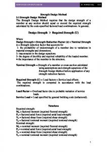
1-9 Design for ACI 318-08: Detail the various aspects of the concrete design procedure that is used by SAFE when the American code [ACI ] is selected. 1-9-1 Design Load Combinations: Various combinations of the load cases for which the structure needs to be designed. For ACI 318-08, a structure is subjected to dead (D), live (L), pattern live (PL), snow (S), wind (W), and earthquake (E) loads. 1-9-2 Limits on Material Strength: SAFE continues to design the members based on the input. 1-9-3 Strength Reduction Factors: The strength reduction factors are applied to the specified strength to obtain the design strength provided by a member as (ACI Code). 1-9-4 Beam Design: SAFE calculates and reports the required areas of reinforcement for flexure, shear, and torsion based on the beam moments, shear forces, torsion, load combination factors, and other criteria described in this section. The reinforcement requirements are calculated at each station along the length of the beam. 1-9-5 Design Flexural Reinforcement: The beam top and bottom flexural reinforcement is designed at each station along the beam. In designing the flexural reinforcement for the major moment of a particular beam, for a particular station, the following steps are involved: Determine factored moments Determine required flexural reinforcement 1-9-6 Determine Factored Moments: In the design of flexural reinforcement of concrete beams, the factored moments for each load combination at a particular beam station are obtained by factoring the corresponding moments for different load cases, with the corresponding load factors.
Design of Reinforced Concrete Slabs by Safe Program
12
Chapter one
Introduction
The beam is then designed for the maximum positive and maximum negative factored moments obtained from all of the load combinations. 1-9-7 Determine Required Flexural Reinforcement: The program calculates both the tension and compression reinforcement. When the applied moment exceeds the moment capacity at this design condition, the area of compression reinforcement is calculated assuming that the additional moment will be carried by compression reinforcement and additional tension reinforcement. 1-9-8 Slab Design: SAFE slab design procedure involves defining sets of strips in two mutually perpendicular directions. The moments for a particular strip are recovered from the analysis, and a flexural design is carried out based on the ultimate strength design method (ACI 318-08). 1-9-9 Design for Flexure: SAFE designs the slab on a strip-by-strip basis. The moments used for the design of the slab elements are the nodal reactive moments, which are obtained by multiplying the slab element stiffness matrices by the element nodal displacement vectors. Those moments will always be in static equilibrium with the applied loads, irrespective of the refinement of the finite element mesh. The design of the slab reinforcement for a particular strip is carried out at specific locations along the length of the strip. These locations correspond to the element boundaries. Controlling reinforcement is computed on either side of those element boundaries. The slab flexural design procedure for each load combination involves the following: Determine factored moments for each slab strip. Design flexural reinforcement for the strip. The maximum reinforcement calculated for the top and bottom of the slab within each design strip, along with the corresponding controlling load combination, is obtained and reported. 1-9-10 Determine Factored Moments for the Strip: Design of Reinforced Concrete Slabs by Safe Program
13
Chapter one
Introduction
For each element within the design strip, for each load combination, the program calculates the nodal reactive moments. The nodal moments are then added to get the strip moments. 1-9-11 Design Flexural Reinforcement for the Strip: The reinforcement computation for each slab design strip, given the bending moment, is identical to the design of rectangular beam sections described earlier. 1-9-12 Minimum and Maximum Slab Reinforcement: The minimum flexural tension reinforcement required for each direction of a slab is given by ACI Limit. 1-9-13 Check for Punching Shear: The punching shear is checked on a critical section at a distance of d/2 from the face of the support (ACI Limit for shear). For rectangular columns and concentrated loads, the critical area is taken as a rectangular area with the sides parallel to the sides of the columns or the point loads. The spacing between adjacent shear reinforcement shall not exceed 2d measured in a direction parallel to the column face. 1-10 Scope of Work: The project works is concerned with the analysis and design of different slabs with beams between interior supports and slabs with edge beam. Analysis of slab using software program (SAFE). A hand calculation used (method II and direct design method for analysis of slabs and compare it with computer program) to show that the safe program is faster and easier for solution than the others method. A computer program for the design of reinforced concrete two-way slabs made by excel worksheet used for design the slabs by method II and direct design method. 1. To use Autocad to sketch the floor plan and the details. 2. To use Microsoft EXCEL to facilitate the computations. 3. To use Safe package for the analysis of Multi story building. 4. To familiarize with ACI Code and other codes. 5. To use Reinforced concrete design Suite for the design of slabs, beams, column. Design of Reinforced Concrete Slabs by Safe Program
14
Chapter Two
Methods of Design and Analysis
Chapter Two
Design Method and Program
Chapter Two Methods of Design and Analysis 2-1 Analysis of Slabs: The slab provides a horizontal surface and is usually supported by columns, beams or walls. Slabs can be categorized into two main types: one-way slabs and two-way slabs. One-way slabs are supported by two opposite sides and bending occurs in one direction only. Two-way slabs are supported on four sides and bending occurs in two directions. One-way slabs are designed as rectangular beams placed side by side. However, slabs supported by four sides may be assumed as one-way slab when the ratio of lengths to width of two perpendicular sides exceeds 2. Although while such slabs transfer their loading in four directions, nearly all load is transferred in the short direction. Two-way slabs carry the load to two directions, and the bending moment in each direction is less than the bending moment of one-way slabs. Also two-way slabs have less deflection than one-way slabs. Compared to one-way slabs, Calculation of two-way slabs is more complex. Methods for two-way slab design and analysis include, Moment Coefficient Method, Direct Design Method (DDM), Equivalent frame method (EFM), Finite element approach, and Yield line theory. This project aims to use one of the most important programs in the analysis and design of concrete Slabs, which is the (SAFE) program for accuracy of the solution and the accuracy of the results provided by program. A slab may be designed by any procedure satisfying conditions for equilibrium and geometrical compatibility. In this chapter, the design method of a two-way reinforced concrete slab is presented. The design procedure adopted in this work is based on provisions of ACI Code (Moment Coefficient Method and direct design method). 2-2 ACI- Moment Coefficient for Two-Way Slab: The values of moment coefficient are calculated for various ratios of dimensions of two-way slabs from 0.55 to 1, and different conditions of the edges supports as shown in Design of Reinforced Concrete Slabs by Safe Program
15
Chapter Two
Design Method and Program
the Tables (2-1). This method applies to solid and ribbed slabs, isolated or continuous, supported on all four sides by walls or beams built monolithically with the slab. The bending moments shall be computed from the formula: 𝑴 = (𝑪𝒐𝒆𝒇𝒇. )𝒘𝒍𝟐𝒔 w = total load per unit area. Is = length of short span, [center to center distance between supports or the clear span plus twice the thickness of slab, whichever is smaller]. The panel may be divided to two column and one middle strips with the middle strip occupying half the width of the panel. The average moment per unit width of the column strip shall be two-thirds of the corresponding moments in the middle strip. Table (2-1) Coefficients of Method II. Slab Case
1 m=
2
3
4
5
Long Direction
Short Direction Position -ve con -ve dis
1 0.033 ---
0.9 0.04 ---
Modular Ratio (m) 0.8 0.7 0.6 0.048 0.055 0.063 -------
0.5 0.083 ---
All 0.033 ---
+ve
0.025
0.03
0.036
0.041
0.047
0.062
0.025
-ve con -ve dis +ve -ve con -ve dis
0.041 0.021 0.031 0.049 0.025
0.048 0.024 0.036 0.057 0.028
0.055 0.027 0.041 0.064 0.032
0.062 0.031 0.047 0.071 0.036
0.069 0.035 0.052 0.078 0.039
0.085 0.042 0.064 0.09 0.045
0.041 0.021 0.031 0.049 0.025
+ve
0.037
0.043
0.048
0.054
0.059
0.068
0.037
-ve con -ve dis +ve -ve con -ve dis
0.058 0.029 0.044 --0.033
0.066 0.033 0.05 --0.038
0.074 0.037 0.065 --0.043
0.082 0.041 0.062 --0.047
0.09 0.045 0.068 --0.053
0.098 0.049 0.074 --0.055
0.058 0.029 0.044 --0.033
+ve
0.05
0.057
0.064
0.072
0.08
0.083
0.05
2-3 Direct design method (DDM): It is an approximate semi-empirical procedure for analyzing two way slab systems. It applies to slab supported by beams or walls, flat slab, flat plates and waffle slabs. The code provides a procedure with which a set of moment coefficients can be determined. The method, in effect, involves a single-cycle moment distribution analysis of the structure based on (a) the estimated flexural stiffness's of the slabs, beams (if any), and columns and Design of Reinforced Concrete Slabs by Safe Program
16
Chapter Two
Design Method and Program
(b) the tensional stiffness's of the slabs and beams (if any) transverse to the direction in which flexural moments are being determined. Some types of moment coefficients have been used satisfactorily for many years for slab design. They do not, however, give very satisfactory results for slabs with unsymmetrical dimensions and loading patterns. Direct Design Method (DDM) for slab systems with or without beams loaded only by gravity loads and having a fairly regular layout meeting the following conditions: 1. There must be three or more continuous spans in each direction. 2. Panels should be rectangular and the long span is no more than twice the short span being measured c to c of supports. 3. Successive span lengths center-to-center of supports in each direction shall not differ by more than 1/3 of the longer span. 4. Columns must be near the corners of each panel with an offset from the general column line of no more 10% of the span in each direction. 5. The opening shout not be of large size in slabs. 6. The live load should not exceed 3 times the dead load in each direction. All loads shall be due gravity only and uniformly distributed over an entire panel. 7. 6-If a panel is supported on all sides by beams, the relative stiffness of those beams in the two perpendicular directions, as measured by the following expression: 8. 0,2 ≤
∝𝑓1 𝑙22 ∝𝑓2 𝑙12
≤ 5 where
Shall not be less than 0.2 or greater than 5.0.
The panels are divided into column and middle strips, as shown in Figure below, and positive and negative moments are estimated in each strip. The column strip is a slab with a width on each side of the column centerline equal to one-fourth the smaller of the panel dimensions l1 or l2. It includes beams if they are present. The middle strip is the pan of the slab between the two column strips. The part of the moments assigned to the column and middle strips may be assumed to be uniformly spread over the strips. The percentage of the moment assigned to a column strip depends on the effective stiffness of that strip and on its aspect ratio, (where l1 is the length of span, center to center, of supports in the direction in which moments are being determined and l2 is the span length, center to center, of Design of Reinforced Concrete Slabs by Safe Program
17
Chapter Two
Design Method and Program
supports in the direction transverse to l1). Note that the Figure below shows column and middle strips in only one direction. A similar analysis must be performed in the perpendicular direction. The resulting analysis will result in moments in both directions.
Fig. (2-1) Column Strip for slab design by direct design method.
2-4 Depth Limitations: 2-4-1 Slabs without Interior Beams: For a slab without interior beams spanning between its supports and with a ratio of its long span to short span not greater than 2.0, the minimum thickness can be taken from [Table 9.5(c) in the ACI code]. The values selected from the table, however, must not be less than the following values (ACI 9.5.3.2): - Slabs without drop panels 125 mm. - Thickness of those slabs with drop panels outside the panels 100 mm. Table (2-2) Table 9.5 (c): Minimum thickness of slabs without interior beams.
Without drop panels3 Yield Strength fy MPa2
Exterior panels Without edge beams
Interior panels
With edge beams
With drop panels1 Exterior panels Without edge beams
Interior panels
With edge beams
280 ℓn/33 ℓn/36 ℓn/36 ℓn/36 ℓn/40 ℓn/40 420 ℓn/30 ℓn/33 ℓn/33 ℓn/33 ℓn/36 ℓn/36 520 ℓn/28 ℓn/31 ℓn/31 ℓn/31 ℓn/34 ℓn/34 1-For two-way construction, (ℓn is the length of clear span in the long direction, measured face-to-face of supports in slabs. without beams and face-to face of beams or other supports in other cases. Design of Reinforced Concrete Slabs by Safe Program
18
Chapter Two
Design Method and Program
2-for fy between the values given in the table, minimum thickness shall be determined by linear Interpolation. 3-Slabs with beams between columns along exterior edges. The value of αf for the edge beam shall not be less than 0.8.
Very often slabs are built without interior beams between the columns but with edge beams running, around the perimeter of the building. These beams are very helpful in stiffening the slabs and reducing the deflections in the exterior slab panels. The stiffness of slabs with edge beams is expressed as a function of αf , which used to represent the ratio of the flexural stiffness (EcbIb) of a beam section to the flexural stiffness of the slab (EcsIs) whose width equals the distance between the centerlines of the panels on each side of the beam. If no beams are used, as in the case for the flat plate, αf will equal 0. For slabs with beams between columns along exterior edges, αf for the edge beams may not be < 0.8. 𝛼𝑓 =
𝐸𝑐𝑏 𝐼𝑏 𝐸𝑐𝑠 𝐼𝑠
Ecb = the modulus of elasticity of the beam concrete. Ecs= the modulus of elasticity of the column concrete. lb=the cross moment of inertia about the centroidal axis of a section made up of the beam and the slab on each side of the beam extending a distance equal to the projection of the beam above or below the slab (whichever is greater,) but not exceeding four times the slab thickness (ACI 13.2.41). ls = the moment of inertia of the gross section of the slab taken about the centroidal axis and equal to h 3/12 limes the slab width, where the width is the same as for α. For monolithic or fully composite construction, a beam includes that portion of slab on each side of the beam extending a distance equal to the projection of the beam above or below the slab, whichever is greater, but not greater than four times the slab thickness.
Fig (2-2). Examples of the portion of slab to be included with the beam under 13.2.4
Design of Reinforced Concrete Slabs by Safe Program
19
Chapter Two
Design Method and Program
2-4-2 Slabs with Interior Beams: To determine the minimum thickness of slabs with beams spanning between their supports on all sides, Section 9.5.3.3 of the code must be followed. Involved in the expressions presented there are span lengths, panel shapes, flexural stiffness of beams, steel yield stresses, and so on. In these equations, the following terms are used: ℓn = the clear span in the long direction, measured face to face, of beams. β = the ratio of the long to the short clear span. αfm = the average value of the ratios of beam-to-slab stiffness on all sides of a panel. The minimum thickness of slabs or other two-way construction may be obtained by substituting into the equations to follow, which are given in Section 9.5.3.3 of the code. In the equations, the quantity p is used to take into account the effect of the shape of the panel on its deflection, while the effect of beams (if any) is represented by αfm. a) For αfm< 0.2, the minimum thicknesses are obtained as they were for slabs without interior beams spanning between their supports. b) For 0,2 2.0, the thickness shall not be less than 90 mm. 𝑙
ℎ=
𝑓𝑦 𝑛(0.8+ 1400)
36+5 𝛽
2-5 Distribution of Moments in Slabs: The basic design procedure of a two-way slab system has five steps. 1. Determine moments at critical sections in each direction, normally the negative moments at supports and positive moment near mid-span. 2. Distribute moment's transverse at critical sections to column and middle-strip and if beams are used in the column strip, distribute column strip moments between slab and beam. 3. Determine the area of steel required in the slab at critical sections for column and middle strips. Design of Reinforced Concrete Slabs by Safe Program
20
Chapter Two
Design Method and Program
4. Select reinforcing bars for the slab and concentrate bars near the column, if necessary. The critical section for negative bending moment is taken at the face of rectangular supports, or at the face of an equivalent square support. The total moment, Mo, which is resisted by a slab equals the sum of the maximum positive and negative moments in the span. It is the same as the total moment that occurs in a simply supported beam. For a uniform load per unit area, qu, it is as follows: 𝑀0 =
(𝑞𝑢 𝑙2 )(𝑙1 )2 8
In this expression, l1, is the span length, center to center, of supports in the direction in which moments are being taken and l2 is the length of the span transverse to l1, measured center to center of the supports. The moment that actually occurs in such a slab has been shown by experience and tests to be somewhat less than the value determined by the above Mo expression. For this reason, l1, is replaced with ln, the clear span measured face to face of the supports in the direction in which moments are taken. The code (13.6.2.5) states that ln may not be taken to be less than 65% of the span l1, measured center to center of supports. If l1, is replaced with ln, the expression for Mo, which is called the static moment, becomes: (𝑞 𝑙 )(𝑙 )2
𝑀0 = 𝑢 2 𝑛 8 When the static moment is being calculated in the long direction, it is convenient to write it as Mo1, and in the short direction as Mos. It is next necessary to know what proportions of these total moments are positive and what proportions are negative. If a slab was completely fixed at the end of each panel, the division would be as it is in a fixed-end beam, two-thirds negative and one-third positive.
Fig. (2-3) Distribution of total static moment Mo to critical sections for positive and negative bending. Design of Reinforced Concrete Slabs by Safe Program
21
Chapter Two
Design Method and Program
This division is reasonably accurate for interior panels where the slab is continuous for several spans in each direction with equal span lengths and loads. In effect, the rotation of the interior columns is assumed to be small, and moment values of 0.65 M0 for negative moment and 0.35 Mo for positive moment are specified by the code (13.6.3.2). For exterior spans, the code (13.6.3.3) provides a set of percentages for dividing the total factored static moment into its positive and negative. These divisions, which are shown in the Table below, include values for unrestrained edges (where the slab is simply supported on a masonry or concrete wall) and for restrained edges (where the slab is constructed integrally with a much reinforced concrete wall so that the little rotation occurs at the slab-to-wall connection). 13.6.3.3 In an end span, total factored static moment, Mo, shall be distributed as follows: Table (2-3) Distribution factors applied to static moment Mo for positive and negative moments in end span. 0) (2) (3) (4) (5) Exterior edge Slab with Slab without beams Exterior unrestrained beams between interior supports edge fully between all Without edge With edge restrained supports beam beam Interior negative factored moment 0.75 0.70 0.70 0.70 0.65 Positive factored moment 0.63 0.57 0.52 0.50 0.35 Exterior negative factored moment 0 0.16 0.26 0.30 0.65
Fig. (2-4) Final distribution of moments.
Design of Reinforced Concrete Slabs by Safe Program
22
Chapter Two
Design Method and Program
The next problem is to estimate what proportion of these moments is taken by the column strips and what proportion is taken by the middle strips. Factored moments in column strips will be as the table below: Table (2-4) Column strip factored moments.
Fig. (2-5) Torsional cross sectional dimensions for βt calculations.
where βt is calculated in Eq. (13-5) and C is calculated in Eq. (13-6). 𝛽𝑡 =
𝐸𝑐𝑏 𝐶 2𝐸𝑐𝑠 𝑙𝑠
𝑥 𝑥 3𝑦 𝐶 = ∑ (1 − 0.63 ) 𝑦 3 The constant C for T- or L-sections shall be permitted to be evaluated by dividing the section into separate rectangular parts, as defined in 13.2.4, and summing the values of C for each part. In Section 13.6.5, the code requires that the beam be allotted 85% of the column strip moment if 𝛼𝑓1
𝑙2 𝑙1
≥ 1.0should𝛼𝑓1
𝑙2 𝑙1
be between 1.0 and 0, the moment allotted to the beam
is determined by linear interpolation from 85% to 0%.
Design of Reinforced Concrete Slabs by Safe Program
23
Chapter Three
Design and Analysis of Slabs by Program and Method II
Chapter Three
Design and Analysis of Slabs by Program and Method II
Chapter Three Design and Analysis of Slabs by Program and Method II 3-1 Slab (work 1) CSI SAFE-Analysis and Design of Slab with interior Beams: 3-1-1 Prosperities and Descriptions of Slabs: Table (3-1) Geometry and Descriptions of Slabs, Beam and Column.
=max clear perimeter/180 =(4.7+3.7)*2000/180=93.333 mm Use h=130 mm From table (9.5 a0 ACI-318) =L/21=5000/21 =238.09 mm Use 500 mm =300 mm for beams. 300*300 mm
Thickness of slab
Depth of beam
Width of beam (b) column
Table (3-2) Concrete and steel Prosperities of slabs, beam and column.
24 kN/m3 30 MPa 400 MPa
Density of concrete Compressive strength (f'c) Yield stress (fy) Table (3-3) Loads Types and Calculations.
Live load (L.L) 4.79 kN/m2 Superimposed dead load (SDL) SDL=2.3 kN/m2 Dead load (D.L) =24*0.13=3.12 kN/m2 W.L=1.6*4.79=7.664 kN/m2 W.D=1.2*(3.12 +2.3)= 6.504 kN/m2 Wu=1.2*(3.12 +2.3)+1.6*4.79=14.168 kN/m2 Calculations of Moments by Method (II):
Ls=Sc/c for all panel. MUEW=WU*LS2*CEW
(C=factors from table of method II factors)
MU NS=WU*LS2*CNS
Design of Reinforced Concrete Slabs by Safe Program
24
Chapter Three
Design and Analysis of Slabs by Program and Method II
Fig. (3-1) 3*3 span slab. Table (3-4) Calculation of Moments for all slabs. Slab
Slab 1 m=0.8 Case=3
Slab 2 m=0.8 Case=2
Slab 3 m=0.8 Case=3
Slab 4 m=0.8 Case=2
Slab 5 m=0.8 Case=1
Ls
Coef
-ve con -ve dis
Short Direction
0.064 0.032
Middle
Column
Mu kN.m/m 14.50803 7.254016
Mu kN.m/m 9.672021 4.836011
Long Direction
0.049 0.025
Middle
Column
Mu kN.m/m 11.10771 5.6672
Mu kN.m/m 7.405141 3.778133
Panel
5m 4m
4m +ve
0.048
10.88102
7.254016
0.037
8.387456
5.591637
-ve con -ve dis
0.055 0.027
12.46784 6.120576
8.311893 4.080384
0.041 0.041
9.294208 9.294208
6.196139 6.196139
+ve
0.041
9.294208
6.196139
0.031
7.027328
4.684885
-ve con -ve dis
0.064 0.032
14.50803 7.254016
9.672021 4.836011
0.049 0.025
11.10771 5.6672
7.405141 3.778133
+ve
0.048
10.88102
7.254016
0.037
8.387456
5.591637
-ve con -ve dis
0.055 0.055
12.46784 12.46784
8.311893 8.311893
0.041 0.021
9.294208 4.760448
6.196139 3.173632
+ve
0.041
9.294208
6.196139
0.031
7.027328
4.684885
-ve con -ve con
0.048 ---
10.88102 10.88102
7.254016 7.254016
0.033 ---
7.480704 7.480704
4.987136 4.987136
+ve
0.036
8.160768
5.440512
0.025
5.6672
3.778133
4m
5m 4m 5m 4m
4m
4m
4m
Design of Reinforced Concrete Slabs by Safe Program
5m 4m 5m 4m
25
Chapter Three Slab 6 m=0.8
Slab 8 m=0.8 Case=2
Slab 9 m=0.8 Case=3
-ve con -ve dis
0.055 0.055
12.46784 12.46784
8.311893 8.311893
0.041 0.021
9.294208 4.760448
6.196139 3.173632
+ve
0.041
9.294208
6.196139
0.031
7.027328
4.684885
-ve con -ve dis
0.064 0.032
14.50803 7.254016
9.672021 4.836011
0.049 0.025
11.10771 5.6672
7.405141 3.778133
+ve
0.048
10.88102
7.254016
0.037
8.387456
5.591637
-ve con -ve dis
0.055 0.027
12.46784 6.120576
8.311893 4.080384
0.041 0.041
9.294208 9.294208
6.196139 6.196139
+ve
0.041
9.294208
6.196139
0.031
7.027328
4.684885
-ve con -ve dis
0.064 0.032
14.50803 7.254016
9.672021 4.836011
0.049 0.025
11.10771 5.6672
7.405141 3.778133
+ve
0.048
10.88102
7.254016
0.037
8.387456
5.591637
4m
Case2
Slab 7 m=0.8 Case=3
Design and Analysis of Slabs by Program and Method II
4m
4m
4m
5m 4m 5m 4m 5m 4m 5m 4m
Fig. (3-2) Multi story (3*3 span slab).
Design of Reinforced Concrete Slabs by Safe Program
26
Chapter Three
Design and Analysis of Slabs by Program and Method II
Fig. (3-3) program definition for design of slabs.
Design of Reinforced Concrete Slabs by Safe Program
27
Chapter Three
Design and Analysis of Slabs by Program and Method II
Fig. (3-4) Entry of slab shape and size.
Design of Reinforced Concrete Slabs by Safe Program
28
Chapter Three
Design and Analysis of Slabs by Program and Method II
Fig. (3-5) Entry of slab and beam and column properties. Design of Reinforced Concrete Slabs by Safe Program
29
Chapter Three
Design and Analysis of Slabs by Program and Method II
Fig. (3-6) Entry of load types and factors. Design of Reinforced Concrete Slabs by Safe Program
30
Chapter Three
Design and Analysis of Slabs by Program and Method II
Fig. (3-7) Deformation shape of slab.
Design of Reinforced Concrete Slabs by Safe Program
31
Chapter Three
Design and Analysis of Slabs by Program and Method II
Design of Reinforced Concrete Slabs by Safe Program
32
Chapter Three
Design and Analysis of Slabs by Program and Method II
Fig. (3-8) results of program (slab forces, beam forces, axial force, stresses, moment, shear, reactions and punching shear). Design of Reinforced Concrete Slabs by Safe Program
33
Chapter Three
Design and Analysis of Slabs by Program and Method II
Fig. (3-9) results of program (slab moment, strip moment if short and long direction).
Design of Reinforced Concrete Slabs by Safe Program
34
Chapter Three
Design and Analysis of Slabs by Program and Method II
Fig. (3-10) results of program (slab design and reinforcement). Design of Reinforced Concrete Slabs by Safe Program
35
Chapter Three
Design and Analysis of Slabs by Program and Method II
Table (3-5) Comparison of moment by method II and Safe. Long Direction Short Direction Slab Moment by Safe Ratio Moment by Safe Ratio Method (II) Program (Method Method (II) Program (Method kN.m Moment II/safe) *100 kN.m Moment II/safe) *100 (DDM) (DDM) kN.m kN.m Slab 1 Slab 2 Slab 3 Slab 4 Slab 5 Slab 6 Slab 7 Slab 8 Slab 9
14.50803 10.88102 7.254016 12.46784 9.294208 6.120576 14.50803 10.88102 7.254016 12.46784 9.294208 12.46784 10.88102 8.160768 10.88102 12.46784 9.294208 12.46784 7.254016 10.88102 14.50803 6.120576 9.294208 12.46784 7.254016 10.88102 14.50803
-8.9269 7.746533 -2.38197 -9.349 7.109733 -2.61887 -8.9269 7.746533 -2.38197 -9.00327 6.4746 -9.00327 -9.2598 5.836833 -9.2598 -9.00327 6.4746 -9.00327 -2.38197 7.746533 -8.9269 -2.61887 7.109733 -9.349 -2.38197 7.746533 -8.9269
-162.52 140.4631 -304.539 -133.36 130.7251 -233.711 -162.52 140.4631 -304.539 -138.481 143.5488 -138.481 -117.508 139.815 -117.508 -138.481 143.5488 -138.481 -304.539 140.4631 -162.52 -233.711 130.7251 -133.36 -304.539 140.4631 -162.52
5.6672 8.387456 11.10771 9.294208 7.027328 9.294208 11.10771 8.387456 5.6672 4.760448 7.027328 9.294208 7.480704 5.6672 7.480704 9.294208 7.027328 4.760448 5.6672 8.387456 11.10771 9.294208 7.027328 9.294208 11.10771 8.387456 5.6672
-3.33715 6.8919 -9.8323 -9.76475 5.8759 -9.76475 -9.8323 6.8919 -3.33715 -3.42085 6.3357 -9.4875 -9.3625 5.12185 -9.3625 -9.4875 6.3357 -3.42085 -3.33715 6.8919 -9.8323 -9.76475 5.8759 -9.76475 -9.8323 6.8919 -3.33715
-169.822 121.7002 -112.972 -95.1812 119.5958 -95.1812 -112.972 121.7002 -169.822 -139.16 110.9164 -97.9627 -79.9007 110.6475 -79.9007 -97.9627 110.9164 -139.16 -169.822 121.7002 -112.972 -95.1812 119.5958 -95.1812 -112.972 121.7002 -169.822
3-2 Slab (work 2) CSI SAFE-Analysis and Design of Slab with Beam: 3-2-1 Prosperities and Descriptions of Slabs: Design slab with beam system 3*3 panels with long direction 6.35 m c/c and short direction 5.6 c/c. The slab is to support a live load of 6 kN/m2 and a dead load of 5 kN/m2, including the slab weight. The columns are 350mm*350mm. the slab is supported by beams along the column line, (300*350 mm), f'c=21 MPa and fy=MPa. Table (3-6) Geometry and descriptions of slabs, beam and column.
Thickness of slab Depth of beam Width of beam (b) Column
=max clear perimeter/180=(5600+6530)*2/180≅150mm Use h=150 mm From table (9.5 a0 ACI-318)=L/21=6350/21 =302.38 mm…Use 350 mm =300 mm for beams. 350*350 mm
Design of Reinforced Concrete Slabs by Safe Program
36
Chapter Three
Design and Analysis of Slabs by Program and Method II
Table (3-7) Concrete Prosperities of slabs, beam and column.
Density of concrete Compressive strength (f'c)
24 kN/m3 21 MPa
Table (3-8) Loads Types and Calculations.
Live load (L.L) Super Imposed Dead load (D.L) Dead load (D.L) Wu=1.2*5+1.6*6=15.6 kN/m2
6 kN/m2 1.4 kN/m2 =24*0.15=3.6
Fig. (3-11) 3*3 span slab and strip position.
Design of Reinforced Concrete Slabs by Safe Program
37
Chapter Three
Design and Analysis of Slabs by Program and Method II
Fig. (3-12) results of program (slab moment, strip moment if short and long direction).
Design of Reinforced Concrete Slabs by Safe Program
38
Chapter Three
Design and Analysis of Slabs by Program and Method II
Fig. (3-13) Deformation shape of slab. Table (3-9) Calculation of Moments for all slabs. Slab
Slab 1 m=0.8 8189 Case= 3 Slab 2 m=0.8 8189 Case= 2 Slab 3 m=0.8 8189 Case= 3 Slab 4 m=0.8 8189 Case= 2 Slab 5 m=0.8 8189 Case= 1 Slab 6 m=0.8 8189
Ls
5.6 m
Coef
-ve con -ve dis +ve
5.6 m
-ve con -ve dis +ve
5.6 m
-ve con -ve dis +ve
5.6 m
-ve con -ve dis +ve
5.6 m
-ve con -ve dis
Short Direction
0.058268 0.028724
Middle
Column
Mu kN.m/m
Mu kN.m/m
28.5055 14.05244
19.00367 9.368294
Long Direction
0.049 0.025
Middle
Column
Mu kN.m/m
Mu kN.m/m
23.97158 12.2304
15.98106 8.1536
Panel
6.35 m 5.6 m
0.043906
21.47928
14.31952
0.037
18.10099
12.06733
0.049268 0.024543
24.10256 12.00698
16.06837 8.004652
0.041 0.041
20.05786 20.05786
13.3719 13.3719
0.036906
18.05477
12.03651
0.031
15.1657
10.11046
0.058268 0.028724
28.5055 14.05244
19.00367 9.368294
0.049 0.025
23.97158 12.2304
15.98106 8.1536
0.043906
21.47928
14.31952
0.037
18.10099
12.06733
0.049268 0.049268
24.10256 24.10256
16.06837 16.06837
0.041 0.021
20.05786 10.27354
13.3719 6.849024
0.036906
18.05477
12.03651
0.031
15.1657
10.11046
0.041449 0
20.27743 0
13.51828 0
0.033 0
16.14413 0
10.76275 0
6.35 m 5.6 m 6.35 m 5.6 m
6.35 m 5.6 m 6.35 m 5.6 m
+ve 5.6 m
-ve con -ve dis
0.031087
15.20807
10.13871
0.025
12.2304
8.1536
0.049268 0.049268
24.10256 24.10256
16.06837 16.06837
0.041 0.021
20.05786 10.27354
13.3719 6.849024
Design of Reinforced Concrete Slabs by Safe Program
6.35 m 5.6 m 39
Chapter Three Case2 Slab 7 m=0.8 8189 Case= 3 Slab 8 m=0.8 8189 Case= 2 Slab 9 m=0.8 8189 Case= 3
5.6 m
+ve -ve con -ve dis +ve
5.6 m
-ve con -ve dis
Design and Analysis of Slabs by Program and Method II 0.036906
18.05477
12.03651
0.031
15.1657
10.11046
0.058268 0.028724
28.5055 14.05244
19.00367 9.368294
0.049 0.025
23.97158 12.2304
15.98106 8.1536
0.043906
21.47928
14.31952
0.037
18.10099
12.06733
0.049268 0.024543
24.10256 12.00698
16.06837 8.004652
0.041 0.041
20.05786 20.05786
13.3719 13.3719
0.036906
18.05477
12.03651
0.031
15.1657
10.11046
0.058268 0.028724
28.5055 14.05244
19.00367 9.368294
0.049 0.025
23.97158 12.2304
15.98106 8.1536
0.043906
21.47928
14.31952
0.037
18.10099
12.06733
6.35 m 5.6 m 6.35 m 5.6 m
+ve
5.6 m
-ve con -ve dis
6.35 m 5.6 m
+ve
Table (3-10) comparison of moment by method II and Safe. Slab Moment by Method (II) kN.m
Slab 1 Slab 2 Slab 3 Slab 4 Slab 5 Slab 6 Slab 7 Slab 8 Slab 9
12.2304 18.10099 23.97158 20.05786 15.1657 20.05786 23.97158 18.10099 12.2304 10.27354 15.1657 20.05786 16.14413 12.2304 16.14413 20.05786 15.1657 10.27354 12.2304 18.10099 23.97158 20.05786 15.1657 20.05786 23.97158 18.10099 12.2304
Long Direction Safe Ratio Program (Method Moment II/safe) *100 (DDM) kN.m -4.52407 -270.341 21.89564 82.66937 -27.297 -87.8176 -26.5195 -75.6343 15.54786 97.54206 -26.5194 -75.6347 -27.2972 -87.8169 21.89586 82.66856 -4.52425 -270.33 -4.80132 -213.973 21.61257 70.17073 -30.3491 -66.0904 -29.3213 -55.0595 13.98061 87.48118 -29.3218 -55.0585 -30.3483 -66.0922 21.6115 70.17421 -4.80279 -213.908 -4.52407 -270.341 21.89564 82.66937 -27.297 -87.8176 -26.5195 -75.6343 15.54786 97.54206 -26.5194 -75.6347 -27.2972 -87.8169 21.89586 82.66856 -4.52425 -270.33
Design of Reinforced Concrete Slabs by Safe Program
Moment by Method (II) kN.m 28.5055 21.47928 14.05244 -2.6947 16.83963 -19.7723 28.5055 21.47928 14.05244 24.10256 18.05477 24.10256 20.27743 15.20807 20.27743 24.10256 18.05477 24.10256 14.05244 21.47928 28.5055 12.00698 18.05477 24.10256 14.05244 21.47928 28.5055
Short Direction Safe Ratio Program (Method Moment II/safe) *100 (DDM) kN.m -17.1916 -165.811 18.54355 115.8315 -2.09696 -670.135 12.00698 -445.577 18.05477 107.2159 24.10256 -121.9 -17.1916 -165.811 18.54355 115.8315 -2.09696 -670.135 -16.9285 -142.379 11.78346 153.2212 -16.9285 -142.379 -19.2395 -105.395 8.962873 169.6785 -19.2395 -105.395 -16.928 -142.383 11.78366 153.2187 -16.928 -142.383 -2.09696 -670.135 18.54355 115.8315 -17.1916 -165.811 -2.6947 -445.577 16.83963 107.2159 -19.7723 -121.9 -2.096 -670.441 18.55797 115.7415 -17.1923 -165.804
40
Chapter Four
Design and Analysis of Slabs by Program and Direct Design Methods
Chapter Four
Calculation by Direct Design Method and Compare with Program
Chapter Four Design and Analysis of Slabs by Program and Direct Design Methods 4-1 Types of Slabs and method of Calculations (Direct Design Method): When the ratio of (L/S) is less than 2 the slab is called two way slab, bending will take place in the two directions, the main reinforcement is required in the two directions.
Fig. (4-1)Type of two-way slabs and method of design.
Fig. (4-2) Muli-span slab. Design of Reinforced Concrete Slabs by Safe Program
41
Chapter Four
Calculation by Direct Design Method and Compare with Program
4-1-1 Direct design Method (D.D.M):
4-1-2 Determination of two way slab thickness:
Design of Reinforced Concrete Slabs by Safe Program
42
Chapter Four
Calculation by Direct Design Method and Compare with Program
Case 2: interior beam are not existing, thickness can be found according to table below: Table (4-1) minimum thickness of slabs without interior beams.
4-1-3 Estimating dimensions of Interior and Exterior Beams Sections:
Fig. (4-3) Effective beam section (a-interior beam, b-exterior beam).
4-1-4 Design Procedure:
Design of Reinforced Concrete Slabs by Safe Program
43
Chapter Four
Calculation by Direct Design Method and Compare with Program
Table (4-2) distribution of total static moment in end spans.
Static moment Mo distributed as follows:
Fig. (4-4) Moment distribution.
Design of Reinforced Concrete Slabs by Safe Program
44
Chapter Four
Calculation by Direct Design Method and Compare with Program
Design of Reinforced Concrete Slabs by Safe Program
45
Chapter Four
Calculation by Direct Design Method and Compare with Program
Table (4-3) column strip factored moments.
4-1-5 Analysis of Slabs by Direct Design Method: This method depends on division of slabs to separated strip and every strip is divided to column strip and middle strip. This strip depends on dimension of each slab. Moment calculated in the end and the middle of each span by using factors depends on charts and tables. 4-2 Slab (work 3) CSI SAFE-04-Analysis and Design of Slab without Interior Beam by Direct Design Method: Building consist of 4 span with properties as shown in tables below. 4-2-1 Prosperities and Descriptions of Slabs: Multi story building (residence) consist of 4 story: Table (4-4) Geometry and descriptions of slabs, beam and column. Thickness of slab
=Ln=33=6.4*1000/33=193.94 mm Use h=200 mm =(7.7+6.7)*2000/180=160mm
Design of Reinforced Concrete Slabs by Safe Program
46
Chapter Four
Calculation by Direct Design Method and Compare with Program
Use h=200 mm From table ACI-Code table 9.5c hs=Ln/33=6.4*1000/33=193.94 mm (fy=420MPa). ACI-Code table 9.5a hb=L/21=7000*1000/21=333.33 mm use Use hb=500 mm. =400 mm *500 for beams. Width of edge beam (b) 400*400 mm Column 600*600 mm Table (4-5) Concrete and Steel Prosperities of slabs, beam and column. Depth of beam
Density of concrete Compressive strength (f'c) fy
24 kN/m3 40 MPa 420 MPa
Table (4-6) Loads Types and Calculations.
Live load (L.L) Superimposed dead load (SDL) Dead load (D.L) W.L=1.6*3=4.8 kN/m2 W.D=1.2*(4.8+2)=8.16 kN/m2 Wu=1.2*(4.8+2)+1.6*3=12.96kN/m2
3 kN/m2 SDL=24*0.07+0.025*1275*10/1000 =2 kN/m2 =24*0.2=4.8 kN/m2
Fig. (4-5) full map for building by safe program. Design of Reinforced Concrete Slabs by Safe Program
47
Chapter Four
Calculation by Direct Design Method and Compare with Program
Fig. (4-6) full map for building by Auto-Cad program.
Strip A
Strip A Strip C
Strip B
Strip D
Fig. (4-7) Design strips for calculations of moments by safe program. Design of Reinforced Concrete Slabs by Safe Program
48
Chapter Four
Calculation by Direct Design Method and Compare with Program
Calculation of constant βt:
Table (4-7) Calculation of Moments for all slabs. Design of Reinforced Concrete Slabs by Safe Program
49
31.2910
2.81348
8.3354
8.915962
50.5237
19.8132
28.729
3
5.6
1.5
152.4096
ve-
0.7
106.68672
0.75
80.01504
12.00226
68.0127
26.6716
38.673
3
6.6
1.5
211.7016
ve -
0.7
148.19112
0.75
111.1433
16.6715
94.4718
37.0477
53.719
3
6.6
1.5
211.7016
ve+
0.35
74.09556
0.7928
58.74296
8.811444
49.9315
15.3526
24.164
3 6. 5 6. 5 6. 5 6. 5 6. 5 6. 5
6.6
1.5
211.7016
ve-
0.65
137.60604
0.7928
109.0941
16.36411
92.7299
28.5119
44.876
5.5
3
318.5325
ve -
0.26
82.81845
0.9335
77.31102
77.31102
0
5.50742
5.5
3
318.5325
ve+
0.52
165.6369
0.6
99.38214
99.38214
0
66.2547
5.5
3
318.5325
ve-
0.7
222.97275
0.75
167.2296
167.2296
0
55.7431
6.4
3
431.3088
ve -
0.7
301.91616
0.75
226.4371
226.4371
0
75.4790
6.4
3
431.3088
ve+
0.35
150.95808
0.6
90.57485
90.57485
0
60.3832
6.4
3
431.3088
ve-
0.65
280.35072
0.75
210.263
210.263
0
70.0876
7
5.5
3
343.035
ve -
0.26
89.1891
7
5.5
3
343.035
ve+
0.52
7
5.5
3
343.035
ve-
7
6.4
3
464.4864
7
6.4
3
7
6.4
3
3
6.6
3
5.4994
107.0269
107.0269
0
71.3512
0.7
240.1245
0.75
180.0934
180.0934
0
60.0311
ve -
0.7
325.14048
0.75
243.8554
243.8554
0
81.2851
464.4864
ve+
0.35
162.57024
0.6
97.54214
97.54214
0
65.0281
464.4864
ve-
0.65
301.91616
0.75
226.4371
226.4371
0
75.4790
1.5
211.7016
ve -
0.65
137.60604
0.7928
109.0941
109.0941
0
28.5119
6.6
1.5
211.7016
ve+
0.35
74.09556
0.7928
58.74296
58.74296
0
15.3526
3
6.6
1.5
211.7016
ve-
0.7
148.19112
0.75
111.1433
111.1433
0
37.0477
3
5.6
1.5
152.4096
ve -
0.7
106.68672
0.75
80.01504
80.01504
0
26.6716
3
5.6
1.5
152.4096
ve+
0.52
79.252992
0.75
59.43974
59.43974
0
19.8132
3
5.6
1.5
152.4096
ve-
0.26
39.626496
0.929
36.81301
36.81301
0
2.81348
Interior Span End Span
0
Interior Span
83.6897
End Span
83.6897
178.3782
0.9383 4 0.6
End Span
For comparison we choose (Strip B and C as interior strip) which solved by direct design method and Program (Safe). Table (4-8) Comparison of Moments for Strip (B). Column Strip Moments Direct Design Position Positon Method Moment (Safe) (DDM) kN.m CSA7 Start 77.3 CSA7 Middle 99.38 CSA7 End 167.23 CSA9 Start 210.26 CSA9 Middle 90.57 CSA9 End 210.26 CSA10 Start 210.26 Design of Reinforced Concrete Slabs by Safe Program
Safe Program Moment (DDM) kN.m 70.185 83.3507 171.5038 183.8408 100.2148 191.3519 191.3519
Ratio (DDM/safe) *100 110.1375 119.2312 97.50804 114.3707 90.37587 109.8813 109.8813 50
End Span Interior Span
(kN.m)
CS.F
Total Slab Moment
5.521952
59.43974
MSM
36.81301
0.75
(kN.m)
0.929
79.252992
M Beam
39.626496
0.52
(kN.m)
0.26
ve+
MCS Slab
ve -
152.4096
MCS
152.4096
1.5
(kN.m)
1.5
5.6
positive and negative moments
5.6
3
L.F
3
Interior Span
Strip D
Mo= WuL2Ln/ 8(kN.m)
Strip C
CS width (m)
Strip B
LN (m)
Strip A
Calculation by Direct Design Method and Compare with Program
L2 (m)
Strip
Chapter Four
Chapter Four
Calculation by Direct Design Method and Compare with Program
CSA10 Middle 90.57 CSA10 End 210.26 CSA11 Start 167.23 CSA11 Middle 99.38 CSA11 End 77.3 Table (4-9) Comparison of Moments for Strip (C). Column Strip Moments Direct Design Position Positon Method Moment (Safe) (DDM) kN.m CSA7 Start 83.6897 CSA7 Middle 107.0269 CSA7 End 180.0934 CSA9 Start 243.8554 CSA9 Middle 97.54214 CSA9 End 226.4371 CSA10 Start 226.4371 CSA10 Middle 97.54214 CSA10 End 243.8554 CSA11 Start 180.0934 CSA11 Middle 107.0269 CSA11 End 83.6897
100.2148 183.8408 171.5038 83.3507 70.185
90.37587 114.3707 97.50804 119.2312 110.1375
Safe Program Moment (DDM) kN.m 73.1302 85.5006 179.5311 192.7916 102.1589 200.221 200.221 102.1589 192.7916 179.5311 85.5006 73.1302
Ratio (DDM/safe) *100 114.4 125.2 100.3 126.5 95.5 113.1 113.1 95.5 126.5 100.3 125.2 114.4
Fig.(4-8) moment in negative and positive in slab.
Design of Reinforced Concrete Slabs by Safe Program
51
Chapter Four
Calculation by Direct Design Method and Compare with Program
Fig. (4-9) Column Strip Moment by Safe Program.
4-3 Slab (work 4) CSI SAFE-04-Analysis and Design of Slab without Interior Beam by Direct Design Method: 4-3-1 Prosperities and Descriptions of Slabs: For the two-way solid slab with beams on all column lines, shown in Figure, evaluate the moments, using the direct design method. All columns are 300× 300 mm in cross section, all beams are 300× 600 mm in cross section, slab thickness is equal to 140 mm. Use f'c= 28 MPa and fy 420 MPa. (L.L=4 kN/m2, D.L=1.83 kN/m2 and SD.L=3.36 kN/m2).
Design of Reinforced Concrete Slabs by Safe Program
52
Chapter Four
Calculation by Direct Design Method and Compare with Program
Fig. (4-10) Two way Solid Slab with beams.
Strip A
Fig. (4-11) Design strips for calculations of moments by direct design Method.
Evaluate the constants α and βt: Beam sectional properties are shown in Figure. Calculation of relative beam stiffness α : Internal beams: relative stiffness of beam is calculated as follows:
Fig. (4-12) Beam sectional properties for relative stiffness calculations. Design of Reinforced Concrete Slabs by Safe Program
53
Chapter Four
Calculation by Direct Design Method and Compare with Program
Calculation of constant βt:
Fig. (4-13) Beam Sectional Properties for relative stiffness calculation.
Design of Reinforced Concrete Slabs by Safe Program
54
Chapter Four
Calculation by Direct Design Method and Compare with Program
3- Evaluation of moments in one of the internal beams: For comparison we choose (Strip A as interior strip) which solved by direct design method and Program (Safe).
5.7
3
6
5.7
3
6
5.7
3
6
5.7
3
6
5.7
3
307.712 307.712 307.712 307.712 307.712
ve -
0.7
ve+
0.35
ve-
0.65
ve -
0.7
ve+
0.57
ve-
0.16
215.399 107.6995 200.0133 215.399 175.3963 49.23405
41.84894
6.277341
35.5716
7.3851
0.75
131.5472
19.73208
111.8151
43.849
0.75
161.5492
24.23238
137.3168
53.849
0.75
161.5492
24.23238
137.3168
53.849
0.75
80.77461
12.11619
68.65842
26.924
0.75
150.01
22.5015
127.5085
50.003
0.75
161.5492
24.23238
137.3168
53.849
0.75
131.5472
19.73208
111.8151
43.849
0.85
41.84894
6.277341
35.5716
7.3851
Table (4-11) Comparison of Moments for Strip (A). Column Strip Moments Direct Design Method Position (Safe) Positon Moment (DDM) kN.m CSA1 Start 13.63215 CSA1 Middle 63.44018 CSA1 End 77.90899 CSA2 Start 77.90899 CSA2 Middle 38.95449 CSA2 End 72.34406 CSA3 Start 77.90899 CSA3 Middle 63.44018 CSA3 End 13.63215
Design of Reinforced Concrete Slabs by Safe Program
Safe Program Moment (DDM) kN.m 14.86 51.548 86.10 79.84 34.2034 79.84 86.10 51.548 14.86
13.63215 63.44018 77.90899 77.90899 38.95449 72.34406 77.90899 63.44018 13.63215
Ratio (DDM/safe) *100 91.73721 123.0701 90.48663 97.5814 113.8907 90.6113 90.48663 123.0701 91.73721
55
End Span
6
307.712
215.399
0.85
Interior Span
3
0.7
Total Slab Moment
5.7
ve-
(kN.m)
6
307.712
175.3963
MSM
3
0.57
(kN.m)
5.7
ve+
M Beam
6
307.712
49.23405
(kN.m)
3
0.16
MCS Slab
5.7
ve -
(kN.m)
6
307.712
MCS
3
CS.F
5.7
positive and negative moments
6
L.F
CS width (m) Mo= WuL2Ln/ 8(kN.m)
LN (m)
Strip A
L2 (m)
Strip
Table (4-10) Calculation of Moments for all slabs.
Chapter Four
Calculation by Direct Design Method and Compare with Program
Strip A
Fig. (4-14) Design strips and strip moment by safe program.
Fig.(4-15) moment in negative and positive in slab.
4-4 Slab (work 5) CSI SAFE-02-Analysis and Design of Slab with Beam: 4-4-1 Prosperities and Descriptions of Slabs: For the two-way solid slab with beams on all column lines, shown in Figure, evaluate the moments, using the direct design method. All columns are 300× 300 mm in cross section. Beams are (300× 500 mm) and (300× 400 mm) in cross section, slab thickness is equal to 160 mm. Use f'c= 28 MPa and fy 420 MPa. (L.L=4 kN/m2, D.L=24*0.16 kN/m2 and SD.L=3.84 kN/m2).
Design of Reinforced Concrete Slabs by Safe Program
56
Chapter Four
Calculation by Direct Design Method and Compare with Program
Fig. (4-16) full map for building by safe program. Design of Reinforced Concrete Slabs by Safe Program
57
Chapter Four
Calculation by Direct Design Method and Compare with Program
Fig. (4-17)beam shape and position by safe program.
Strip A
Strip A
Fig. (4-18) Design strips for calculations of moments by direct design Method. Design of Reinforced Concrete Slabs by Safe Program
58
Chapter Four
Calculation by Direct Design Method and Compare with Program
Design of Reinforced Concrete Slabs by Safe Program
59
Chapter Four
Calculation by Direct Design Method and Compare with Program
Design of Reinforced Concrete Slabs by Safe Program
60
Chapter Four
Calculation by Direct Design Method and Compare with Program
Design of Reinforced Concrete Slabs by Safe Program
61
Chapter Four
Calculation by Direct Design Method and Compare with Program
For comparison we choose (Strip A as exterior strip) which solved by direct design method and Program (Safe).
138.018
ve-
0.65
48.30661 89.71227
0.75 0.75
61.90146
9.28522
29.53562
4.430344
61.90146
9.28522
2.760377
5.6587
46.1404
24.38793
32.530
56.66365
29.9501
39.949
52.61624
27.8108
37.096
25.10528
18.77098
23.201
52.61624
27.8108
37.096
For comparison we choose (Strip A as interior strip) which solved by direct design method and Program (Safe). Table (4-13) Comparison of Moments for Strip (A). Column Strip Moments Direct Design Position Positon Method Moment (Safe) (DDM) kN.m CSA1 Start 5.6587 CSA1 Middle 32.530 CSA1 End 39.949 CSA2 Start 37.09 CSA2 Middle 23.20 CSA2 End 37.096 CSA3 Start 39.949 CSA3 Middle 32.530 CSA3 End 5.6587
Design of Reinforced Concrete Slabs by Safe Program
Safe Program Moment (DDM) kN.m 6.655 39.8853 33.4648 33.2496 25.365 33.2516 33.4648 39.8853 6.655
Ratio (DDM/safe) *100 85.0 81.6 119.4 111.6 91.5 111.6 119.4 81.6 85.0
62
End Span
0.35
0.75
9.999467
16.42425
Interior Span
1.5
ve+
89.71227
66.66312
Total Slab Moment
4.7
138.018
0.65
0.75
8.142423
(kN.m)
3.15
1.5
ve -
96.61321
54.28282
MSM
4.7
138.018
0.7
0.75
2.898396
(kN.m)
3.15
1.5
ve-
78.67076
19.32264
M Beam
4.7
138.018
0.57
0.85
(kN.m)
3.15
1.5
ve+
22.08302
MCS Slab
4.7
138.018
0.16
MCS
3.15
1.5
ve -
(kN.m)
4.7
138.018
CS.F
3.15
1.5
positive and negative moments
4.7
L.F
3.15
CS width (m) Mo= WuL2Ln/ 8(kN.m)
LN (m)
Strip A
L2 (m)
Strip
Table (4-12) Calculation of Moments for all slabs.
Chapter Four
Calculation by Direct Design Method and Compare with Program
Fig. (4-19) Design strips and strip moment by safe program.
4-5 Slab (work 6) CSI SAFE-04-Analysis and Design of Slab with Interior Beam by Direct Design Method: Solving the same work (work2) but with direct design method.
Fig. (4-20) Two way slabs dimensions.
Design of Reinforced Concrete Slabs by Safe Program
63
Chapter Four
Calculation by Direct Design Method and Compare with Program
Assume a depth for the slab : ℎ=
𝑝𝑒𝑟𝑖𝑚𝑒𝑡𝑒𝑟 𝑜𝑓 𝑝𝑎𝑛𝑙𝑒
ℎ=
180
2∗(6530+5600) 180
≅ 150 𝑚𝑚
Check depth limitations: Calculate beams and slab moment of inertia : 150 350
350 350 350
𝑁. 𝐴 𝑓𝑟𝑜𝑚 𝑡𝑜𝑝 (𝑦̅) =
All unit in mm 5002 1502 +350∗ 2 2
350∗
350
𝑦̅ = 209.6 𝑚𝑚
350∗500+350∗150
𝑏 ∗ ℎ3 + (𝐴 ∗ 𝑑2 ) 12 (350 + 350) ∗ 209.63 350 ∗ (500 − 209.6)3 350 ∗ (209.6 − 150)3 𝐼𝑏1 = + − = 4.98 ∗ 109 𝑚𝑚4 3 3 3 𝐼𝑏1 =
𝑁. 𝐴 𝑓𝑟𝑜𝑚 𝑡𝑜𝑝 (𝑦̅) =
2∗350∗
1502 5002 +350∗ 2 2
2∗350∗150+350∗500
𝑦̅ = 184.375 𝑚𝑚
184.3753 (500 − 184.375)3 2 ∗ 350 ∗ (184.375 − 150)3 + 350 ∗ − 3 3 3 9 4 = 5.85 ∗ 10 𝑚𝑚 Compute the value of Is in the edge strip, interior strip &∝ 𝒇 : (6350 + 350⁄2) ∗ 1503 𝐼𝑠 𝑒𝑑𝑔𝑒 𝑠𝑡𝑟𝑖𝑝 = = 0.94 ∗ 109 𝑚𝑚4 12 𝐼𝑏2 = (2 ∗ 350 + 350) ∗
∝ 𝑓1 =
4.98∗109
𝐸𝑐𝑏 ∗ 𝐼𝑏1
∝ 𝑓1 = 0.94∗109 = 5.3
𝐸𝑐𝑠 ∗ 𝐼𝑠
𝐼𝑠2 𝑖𝑛𝑡𝑒𝑟𝑖𝑜𝑟 5.6 𝑙𝑜𝑛𝑔 𝑠𝑡𝑟𝑖𝑝 = ∝ 𝑓2 =
𝐸𝑐𝑏 ∗ 𝐼𝑏2 𝐸𝑐𝑠 ∗𝐼𝑠2
(6350 + 6350⁄2) ∗ 1503 = 1.79 ∗ 109 𝑚𝑚4 12 5.85∗109
∝ 𝑓2 = 1.79∗109 = 3.27
Design of Reinforced Concrete Slabs by Safe Program
64
Chapter Four
Calculation by Direct Design Method and Compare with Program
𝐼𝑠3 𝑖𝑛𝑡𝑒𝑟𝑖𝑜𝑟 6.35 𝑙𝑜𝑛𝑔 𝑠𝑡𝑟𝑖𝑝 =
5600 ∗ 1503 = 1.575 ∗ 109 𝑚𝑚4 12
∝ 𝑓3 =
5.85∗109
𝐸𝑐𝑏 ∗ 𝐼𝑏2 𝐸𝑐𝑠 ∗𝐼𝑠3
∝ 𝑓3 = 1.575∗109 = 3.7
*limitation in code: ∝𝑓1 ∗𝑙22 ∝𝑓2 ∗𝑙12
3.7∗5.62
= 3.27∗6.352 = 0.9
0.9 > 0.2
5.3 + 3.2 7 + 3.7 + 3.7 ≅4 4 6350−350 ∵∝ 𝑓𝑚 > 2.0 𝛽 = 5600−350 = 1.14 ∝ 𝑓𝑚 =
∴ ℎ𝑚𝑖𝑛, =
6000∗(0.8+
280 ) 1400
36+5∗(1.14)
= 143.9 < 150 𝑚𝑚
∴ ℎ𝑎𝑠𝑠𝑢𝑚𝑒𝑑,=150 𝑚𝑚 𝑖𝑠 𝑜𝑘
Find Moments: Short direction /Exterior strip / Interior panel: 𝑀𝑜 =
15.6 ∗ (3.175 + 0.35⁄2) ∗ (5.6 − .35)2 8
= 180 𝑘𝑁. 𝑚
−𝑣𝑒 𝑀 = 0.65 ∗ 180 = 117 𝑘𝑁. 𝑚 +𝑣𝑒 𝑀 = 0.15 ∗ 180 = 27 𝑘𝑁. 𝑚 𝑙2 6.35 𝑙2 ∝ 𝑓1 = 5.3 = = 1.13 ∝ 𝑓1 = 6 𝑙1 5.6 𝑙1 −𝑣𝑒 𝑀 = 117 𝑘𝑁. 𝑚 +𝑣𝑒 𝑀 = 27 𝑘𝑁. 𝑚 C.s % portion(table13.6.4.1)=0.72 C.s % portion(table13.6.4.4)=0.72 −𝑣𝑒 𝑀 𝑐. 𝑠 = 0.72 ∗ 117 = 84.24 𝑘𝑁. 𝑚 +𝑣𝑒 𝑀 𝑐. 𝑠 = 0.72 ∗ 27 = 19.44 𝑘𝑁. 𝑚 −𝑣𝑒 𝑀 𝑚𝑖𝑑𝑑𝑙𝑒 . 𝑠 = 117 − 84.24 +𝑣𝑒 𝑀 𝑚𝑖𝑑𝑑𝑙𝑒. 𝑠 = 27 − 19.44 = 7.56 𝑘𝑁. 𝑚 = 32.76 𝑘𝑁. 𝑚 −𝑣𝑒 𝑀 𝑐. 𝑠 𝑓𝑜𝑟 𝑠𝑙𝑎𝑏 = 0.15 ∗ 84.24 +𝑣𝑒 𝑀 𝑐. 𝑠 𝑓𝑜𝑟 𝑠𝑙𝑎𝑏 = 0.15 ∗ 19.44 = 12.63 𝑘𝑁. 𝑚 = 2.916 𝑘𝑁. 𝑚
Short direction /Exterior strip / Exterior panel 350
𝑐 = ((1 − 0.63 ∗ 500) ∗ ( 𝐼𝑠 =
3350∗1503 12
500∗3503 3
= 0.94 ∗ 109 𝑚𝑚4 𝑀𝑜 =
150
)) +((1 − 0.63 ∗ 350) ∗ ( 4.28∗109
350∗1503 3
) =1.72*1010 mm4
using eq.
𝛽 = 2∗0.94∗109 = 2.27
15.6 ∗ (3.175 + 0.35⁄2) ∗ (5.6 − .35)2
8 From table 13.6.3.3 𝑀𝑜 shall be distributed as follows: −𝑣𝑒 𝑀 𝑖𝑛𝑡. = 0.7 ∗ 180 +𝑣𝑒 𝑀 = 0.57 ∗ 180 = 126 𝑘𝑁. 𝑚 = 102.6 𝑘𝑁. 𝑚 C.s % portion(table13.6.4.1)=0.72 C.s % portion(table13.6.4.4)=0.72 −𝑣𝑒 𝑀 𝑐. 𝑠 = 0.72 ∗ 126 +𝑣𝑒 𝑀 𝑐. 𝑠 = 0.72 ∗ 102.6 = 90.72 𝑘𝑁. 𝑚 = 73.87 𝑘𝑁. 𝑚 −𝑣𝑒 𝑀 𝑚𝑖𝑑𝑑𝑙𝑒 . 𝑠 = 126 − 90.72 +𝑣𝑒 𝑀 𝑚𝑖𝑑𝑑𝑙𝑒. 𝑠 = 102.6 = 35.28 𝑘𝑁. 𝑚 − 73.87 = 28.7 𝑘𝑁. 𝑚 −𝑣𝑒 𝑀 𝑐. 𝑠 𝑓𝑜𝑟 𝑠𝑙𝑎𝑏 +𝑣𝑒 𝑀 𝑐. 𝑠 𝑓𝑜𝑟 𝑠𝑙𝑎𝑏 = 0.15 ∗ 90.72 = 0.15 ∗ 73.87 = 9.72𝑘𝑁. 𝑚 = 11.8𝑘𝑁. 𝑚
Design of Reinforced Concrete Slabs by Safe Program
= 180 𝑘𝑁. 𝑚 −𝑣𝑒 𝑀 𝑒𝑥𝑡. = 0.16 ∗ 180 = 28.8 𝑘𝑁. 𝑚 C.s % portion(table13.6.4.2)=0.746 −𝑣𝑒 𝑀 𝑐. 𝑠 = 28.8 ∗ 0.711 = 20.47 𝑘𝑁. 𝑚 −𝑣𝑒 𝑀 𝑚𝑖𝑑𝑑𝑙𝑒 . 𝑠 = 28.8 − 20.47 = 7.32 𝑘𝑁. 𝑚 −𝑣𝑒 𝑀 𝑐. 𝑠 𝑓𝑜𝑟 𝑠𝑙𝑎𝑏 = 0.15 ∗ 21.48 = 3.07𝑘𝑁. 𝑚
65
Chapter Four
Calculation by Direct Design Method and Compare with Program
Short direction /interior strip /interior panel:
15.6 ∗ 6.35 ∗ (5.6)2 = 342 𝑘𝑁. 𝑚 8 −𝑣𝑒 𝑀 = 0.65 ∗ 342 = 222.3 𝑘𝑁. 𝑚 +𝑣𝑒 𝑀 = 0.35 ∗ 342 = 119.7𝑁. 𝑚 𝑀𝑜 =
𝑙2 6.35 = = 1.13 𝑙1 5.6 −𝑣𝑒 𝑀 = 222.3 𝑘𝑁. 𝑚
𝑙2 = 3.695 𝑙1 +𝑣𝑒 𝑀 = 119.7 𝑘𝑁. 𝑚
∝ 𝑓1 = 3.27
C.s % portion(table13.6.4.1)=0.72 −𝑣𝑒 𝑀 𝑐. 𝑠 = 0.72 ∗ 222.3 = 160.056𝑘𝑁. 𝑚 −𝑣𝑒 𝑀 𝑚𝑖𝑑𝑑𝑙𝑒 . 𝑠 = 222.3 − 160.056 = 62.244 𝑘𝑁. 𝑚 −𝑣𝑒 𝑀 𝑐. 𝑠 𝑓𝑜𝑟 𝑠𝑙𝑎𝑏 = 0.15 ∗ 160.056 = 24 𝑘𝑁. 𝑚
∝ 𝑓1
C.s % portion(table13.6.4.4)=0.72 +𝑣𝑒 𝑀 𝑐. 𝑠 = 0.72 ∗ 119.7 = 86.184 𝑘𝑁. 𝑚 +𝑣𝑒 𝑀 𝑚𝑖𝑑𝑑𝑙𝑒. 𝑠 = 119.7 − 86.184 = 33.516 𝑘𝑁. 𝑚 +𝑣𝑒 𝑀 𝑐. 𝑠 𝑓𝑜𝑟 𝑠𝑙𝑎𝑏 = 0.15 ∗ 86.4 = 12.96 𝑘𝑁. 𝑚
Short direction / interior strip / Exterior panel: 350
𝑐 = ((1 − 0.63 ∗ 500) ∗ (
500∗3503 3
150
)) +((1 − 0.63 ∗ 350) ∗ (
350∗1503
(6350 + 6350⁄2) ∗ 1503 = 1.79 ∗ 109 𝑚𝑚4 12 4.28 ∗ 109 𝛽= = 1.195 2 ∗ 1.79 ∗ 109
3
) =1.72*1010 mm4
𝐼𝑠 =
𝑀𝑜 =
15.6∗6.35∗(5.6)2 8
= 342 𝑘𝑁. 𝑚
From table 13.6.3.3 𝑀𝑜 shall be distributed as follows: −𝑣𝑒 𝑀 𝑖𝑛𝑡. = 0.7 ∗ 342 = 239.4 𝑘𝑁. 𝑚
+𝑣𝑒 𝑀 = 0.57 ∗ 342 = 194.94 𝑘𝑁. 𝑚
C.s % portion(table13.6.4.1)=0.72 −𝑣𝑒 𝑀 𝑐. 𝑠 = 0.72 ∗ 239.4 = 172.368 𝑘𝑁. 𝑚 −𝑣𝑒 𝑀 𝑚𝑖𝑑𝑑𝑙𝑒 . 𝑠 = 239.4 − 172.368 = 67.032 𝑘𝑁. 𝑚 −𝑣𝑒 𝑀 𝑐. 𝑠 𝑓𝑜𝑟 𝑠𝑙𝑎𝑏 = 0.15 ∗ 172.368 = 21.06𝑘𝑁. 𝑚
C.s % portion(table13.6.4.4)=0.72 +𝑣𝑒 𝑀 𝑐. 𝑠 = 0.72 ∗ 194.94 = 140.4 𝑘𝑁. 𝑚 +𝑣𝑒 𝑀 𝑚𝑖𝑑𝑑𝑙𝑒. 𝑠 = 194.94 − 140.4 = 54.54 𝑘𝑁. 𝑚 +𝑣𝑒 𝑀 𝑐. 𝑠 𝑓𝑜𝑟 𝑠𝑙𝑎𝑏 = 0.15 ∗ 140.4 = 21.06𝑘𝑁. 𝑚
−𝑣𝑒 𝑀 𝑒𝑥𝑡. = 0.16 ∗ 342 = 54.72𝑘𝑁. 𝑚 C.s % portion(table13.6.4.2)=0.65 −𝑣𝑒 𝑀 𝑐. 𝑠 = 54.72 ∗ 0.65 = 35.568𝑘𝑁. 𝑚 −𝑣𝑒 𝑀 𝑚𝑖𝑑𝑑𝑙𝑒 . 𝑠 = 54.72 − 35.568 = 19.152 𝑘𝑁. 𝑚 −𝑣𝑒 𝑀 𝑐. 𝑠 𝑓𝑜𝑟 𝑠𝑙𝑎𝑏 = 0.15 ∗ 35.568 = 5.335𝑘𝑁. 𝑚
Long direction /Exterior strip / Interior panel: 𝑀𝑜 =
15.6 ∗ (5.6⁄2 + 0.35⁄2) ∗ (6.35 − 0.35)2
= 208.845 𝑘𝑁. 𝑚 8 −𝑣𝑒 𝑀 = 0.65 ∗ 208.845 = 135.74𝑘𝑁. 𝑚 +𝑣𝑒 𝑀 = 0.35 ∗ 208.845 = 73.09 𝑘𝑁. 𝑚 𝑙2 5.6 𝑙2 ∝ 𝑓1 = 3.27 = = .88 ∝ 𝑓1 = 2.88 𝑙1 6.35 𝑙1 −𝑣𝑒 𝑀 = 135.74 𝑘𝑁. 𝑚 +𝑣𝑒 𝑀 = 73.09𝑘𝑁. 𝑚 C.s % portion(table13.6.4.1)=0.786 C.s % portion(table13.6.4.4)=0.786 −𝑣𝑒 𝑀 𝑐. 𝑠 = 0.786 ∗ 135.74 = 106.69𝑘𝑁. 𝑚 +𝑣𝑒 𝑀 𝑐. 𝑠 = 0.786 ∗ 73.09 = 57.45 𝑘𝑁. 𝑚 −𝑣𝑒 𝑀 𝑚𝑖𝑑𝑑𝑙𝑒 . 𝑠 = 29.05𝑘𝑁. 𝑚 +𝑣𝑒 𝑀 𝑚𝑖𝑑𝑑𝑙𝑒. 𝑠 = 15.636 𝑘𝑁. 𝑚 −𝑣𝑒 𝑀 𝑐. 𝑠 𝑓𝑜𝑟 𝑠𝑙𝑎𝑏 = 0.15 ∗ 106.69 +𝑣𝑒 𝑀 𝑐. 𝑠 𝑓𝑜𝑟 𝑠𝑙𝑎𝑏 = 0.15 ∗ 57.45 = 8.6 𝑘𝑁. 𝑚 = 16 𝑘𝑁. 𝑚
Long direction /Exterior strip / Exterior panel: 350
𝑐 = ((1 − 0.63 ∗ 500) ∗ (
500∗3503 3
))
Design of Reinforced Concrete Slabs by Safe Program
66
Chapter Four
Calculation by Direct Design Method and Compare with Program
150
+((1 − 0.63 ∗ 350) ∗ ( 𝐼𝑠 =
350∗1503
3 (5600⁄2+350⁄2 )∗5600∗1503 12
𝑀𝑜 =
) =1.72*1010 mm4
= 0.836 ∗ 109 𝑚𝑚4
4.28∗109
𝛽 = 2∗0.836∗109 = 2.559
15.6 ∗ (5.6⁄2 + 0.35⁄2) ∗ (6.35 − 0.35)2
8 From table 13.6.3.3 𝑀𝑜 shall be distributed as follows: −𝑣𝑒 𝑀 𝑖𝑛𝑡. = 0.7 ∗ 208.845 +𝑣𝑒 𝑀 = 0.57 ∗ 208.845 = 146.19 𝑘𝑁. 𝑚 = 119.04 𝑘𝑁. 𝑚
= 208.845 𝑘𝑁. 𝑚
C.s % portion(table13.6.4.1)=0.786
C.s % portion(table13.6.4.4)=0.786
−𝑣𝑒 𝑀 𝑒𝑥𝑡. = 0.16 ∗ 208.845 … … . . = 33.4𝑘𝑁. 𝑚 C.s % portion(table13.6.4.2)= 0.786
−𝑣𝑒 𝑀 𝑐. 𝑠 = 0.786 ∗ 146.19 = 114.9𝑘𝑁. 𝑚
+𝑣𝑒 𝑀 𝑐. 𝑠 = 0.786 ∗ 119.04 = 93.56 𝑘𝑁. 𝑚
−𝑣𝑒 𝑀 𝑐. 𝑠 = 33.4 ∗ 0.786 = 26.25𝑘𝑁. 𝑚
−𝑣𝑒 𝑀 𝑚𝑖𝑑𝑑𝑙𝑒 . 𝑠 = 58884. 𝑚
+𝑣𝑒 𝑀 𝑚𝑖𝑑𝑑𝑙𝑒. 𝑠 = 47.953 𝑘𝑁. 𝑚 +𝑣𝑒 𝑀 𝑐. 𝑠 𝑓𝑜𝑟 𝑠𝑙𝑎𝑏 = 0.15 ∗ 93.56 = 14.034𝑘𝑁. 𝑚
−𝑣𝑒 𝑀 𝑚𝑖𝑑𝑑𝑙𝑒 . 𝑠 = 7.14𝑘𝑁. 𝑚
−𝑣𝑒 𝑀 𝑐. 𝑠 𝑓𝑜𝑟 𝑠𝑙𝑎𝑏 = 0.15 ∗ 114.9𝑘 = 17.235𝑘𝑁. 𝑚
−𝑣𝑒 𝑀 𝑐. 𝑠 𝑓𝑜𝑟 𝑠𝑙𝑎𝑏 = 0.15 ∗ 26.25 = 3.93𝑘𝑁. 𝑚
Long direction / Interior strip / Interior panel:
15.6 ∗ 5.6 ∗ (6.35 − 0.35)2 = 393.12 𝑘𝑁. 𝑚 8 −𝑣𝑒 𝑀 = 0.65 ∗ 393.12 = 255.528𝑘𝑁. 𝑚 +𝑣𝑒 𝑀 = 0.35 ∗ 393.12 = 137.592 𝑘𝑁. 𝑚 𝑙2 5.6 𝑙2 ∝ 𝑓1 = 3.27 = = .88 ∝ 𝑓1 = 2.88 𝑙1 6.35 𝑙1 −𝑣𝑒 𝑀 = 255.528 𝑘𝑁. 𝑚 +𝑣𝑒 𝑀 = 137.592 𝑘𝑁. 𝑚 C.s % portion(table13.6.4.1)=0.786 C.s % portion(table13.6.4.4)=0.786 −𝑣𝑒 𝑀 𝑐. 𝑠 = 0.786 ∗ 255.528 = 200.8𝑘𝑁. 𝑚 +𝑣𝑒 𝑀 𝑐. 𝑠 = 0.786 ∗ 137.592 = 108.14 𝑘𝑁. 𝑚 −𝑣𝑒 𝑀 𝑚𝑖𝑑𝑑𝑙𝑒 . 𝑠 = 54.68𝑘𝑁. 𝑚 +𝑣𝑒 𝑀 𝑚𝑖𝑑𝑑𝑙𝑒. 𝑠 = 29.44 𝑘𝑁. 𝑚 −𝑣𝑒 𝑀 𝑐. 𝑠 𝑓𝑜𝑟 𝑠𝑙𝑎𝑏 = 0.15 ∗ 200.8 +𝑣𝑒 𝑀 𝑐. 𝑠 𝑓𝑜𝑟 𝑠𝑙𝑎𝑏 = 0.15 ∗ 108.14 = 30.12 𝑘𝑁. 𝑚 = 16.221𝑘𝑁. 𝑚 𝑀𝑜 =
Long direction / Interior strip / Exterior panel: 350
𝑐 = ((1 − 0.63 ∗ 500) ∗ ( 𝐼𝑠 =
5600∗1503 12
500∗3503 3
150
)) +((1 − 0.63 ∗ 350) ∗ (
= 1.575 ∗ 109 𝑚𝑚4
350∗1503
4.28∗109
3
) =1.72*1010 mm4
𝛽 = 2∗1.575∗109 = 1.349
15.6 ∗ 5.6 ∗ (6.35 − 0.35)2 = 393.12 𝑘𝑁. 𝑚 8 From table 13.6.3.3 𝑀𝑜 shall be distributed as follows: −𝑣𝑒 𝑀 𝑖𝑛𝑡. = 0.7 ∗ 393.12 +𝑣𝑒 𝑀 = 0.57 ∗ 393.12 −𝑣𝑒 𝑀 𝑒𝑥𝑡. = 0.16 ∗ 393.12 = 275.184 𝑘𝑁. 𝑚 = 224.0784 𝑘𝑁. 𝑚 = 62.89𝑘𝑁. 𝑚 C.s % C.s % portion(table13.6.4.4)=0.786 C.s % portion(table13.6.4.2)= 0.786 portion(table13.6.4.1)=0.786 −𝑣𝑒 𝑀 𝑐. 𝑠 = 0.786 ∗ 275.184 +𝑣𝑒 𝑀 𝑐. 𝑠 = 0.786 ∗ 119.04 −𝑣𝑒 𝑀 𝑐. 𝑠 = 33.4 ∗ 0.786 = 216.29𝑘𝑁. 𝑚 = 93.56 𝑘𝑁. 𝑚 = 26.25𝑘𝑁. 𝑚 𝑀𝑜 =
−𝑣𝑒 𝑀 𝑚𝑖𝑑𝑑𝑙𝑒 . 𝑠 = 58884. 𝑚 −𝑣𝑒 𝑀 𝑐. 𝑠 𝑓𝑜𝑟 𝑠𝑙𝑎𝑏 = 0.15 ∗ 114.9𝑘 = 17.235𝑘𝑁. 𝑚
+𝑣𝑒 𝑀 𝑚𝑖𝑑𝑑𝑙𝑒. 𝑠 = 47.953 𝑘𝑁. 𝑚 +𝑣𝑒 𝑀 𝑐. 𝑠 𝑓𝑜𝑟 𝑠𝑙𝑎𝑏 = 0.15 ∗ 93.56 = 14.034𝑘𝑁. 𝑚
Design of Reinforced Concrete Slabs by Safe Program
−𝑣𝑒 𝑀 𝑚𝑖𝑑𝑑𝑙𝑒 . 𝑠 = 7.14𝑘𝑁. 𝑚 −𝑣𝑒 𝑀 𝑐. 𝑠 𝑓𝑜𝑟 𝑠𝑙𝑎𝑏 = 0.15 ∗ 26.25 = 3.93𝑘𝑁. 𝑚
67
Chapter Four
Calculation by Direct Design Method and Compare with Program
Short direction /interior strip /interior panel:
5.6
3.175
342
119.7
ve+
86.184
12.9276
6.35
5.6
3.175
342
222.3
ve-
160.056
24.0084
MCS
Table (4-15) Comparison of Moments for Strip (A). Column Strip Moments Direct Design Position Positon Method Moment (Safe) (DDM) kN.m 86.2524 CSA1 Start 46.4436 CSA1 Middle 86.2524 CSA1 End
Safe Program Moment (DDM) kN.m 97.725 41.612 97.725
62.244 33.516 62.244
Total Slab Moment
6.35
136.04 76 73.256 4 136.04 76
MSM
24.0084
(kN.m)
160.056
(kN.m)
ve -
M Beam
222.3
(kN.m)
342
MCS Slab
3.175
(kN.m)
5.6
Moment factored
CS width (m)
6.35
Mo= WuL2Ln/ 8(kN.m)
LN (m)
Strip
L2 (m)
Strip
Table (4-14) Calculation of Moments for all slabs.
86.2524 46.4436 86.2524
Ratio (DDM/safe) *100 88.26032 111.6111 88.26032
Fig. (4-21) Column Strip Moment by Safe Program.
Design of Reinforced Concrete Slabs by Safe Program
68
Chapter Four
Calculation by Direct Design Method and Compare with Program
4-6 Slab (work 7) CSI SAFE-04-Analysis and Design of Slab with Interior Beam by Direct Design Method: Design slab with beam system 3*3 panels. The slab is to support a live load of 2.728 kN/m2 and a dead load of 4.82 kN/m2, including the slab weight. The columns are (250mm*250mm). The slab is supported by beams along the column line, (250*600 edge beam and 250*500mm internal beam).
Fig. (4-22) Design strips for calculations of moments by safe program.
Frame A
Design of Reinforced Concrete Slabs by Safe Program
69
Chapter Four
Calculation by Direct Design Method and Compare with Program
Design of Reinforced Concrete Slabs by Safe Program
70
Chapter Four
Calculation by Direct Design Method and Compare with Program
Frame B
6 6
Strip A
6 6 6
ve -
0.16
8.920898438
0.8
7.136719
1.070508
6.066211
1.78418
1.5
55.75562
ve+
0.57
31.78070068
0.6
19.06842
2.860263
16.20816
12.71228
1.5
55.75562
ve-
0.7
39.02893066
0.6
23.41736
3.512604
19.90475
15.61157
1.5
55.75562
ve -
0.65
36.2411499
0.6
21.74469
3.261703
18.48299
14.49646
1.5
55.75562
ve+
0.35
19.51446533
0.6
11.70868
1.756302
9.952377
7.805786
1.5
55.75562
ve-
0.65
36.2411499
0.6
21.74469
3.261703
18.48299
14.49646
3
107.0508
ve -
0.16
17.128125
0.8736
14.96313
2.24447
12.71866
2.164995
3
107.0508
ve+
0.57
61.01894531
0.6
36.61137
5.491705
31.11966
24.40758
3
107.0508
ve-
0.7
74.93554688
0.6
44.96133
6.744199
38.21713
29.97422
3
107.0508
ve -
0.65
69.58300781
0.6
41.7498
6.262471
35.48733
27.8332
3
107.0508
ve+
0.35
37.46777344
0.6
22.48066
3.3721
19.10856
14.98711
2.854688 15.57254
End Span
55.75562
19.12417 17.75816 9.562088
Interior Span
1.5
Design of Reinforced Concrete Slabs by Safe Program
Total Slab Moment
MSM
(kN.m)
(kN.m)
M Beam
(kN.m)
MCS Slab
MCS
(kN.m)
CS.F
positive and negative moments
L.F
Mo= WuL2Ln/ 8(kN.m)
CS width (m)
LN (m) 3.7 5 3.7 5 3.7 5 3.7 5 3.7 5 3.7 5 3.7 5 3.7 5 3.7 5 3.7 5 3.7 5
17.75816 4.409465 29.89929
End Span
3.1 25 3.1 25 3.1 25 3.1 25 3.1 25 3.1 25
36.71842 34.09567 18.35921
71
Interi or Span
Strip B
L2 (m)
Strip
Table (4-16) Calculation of Moments for all slabs.
Chapter Four 6
3.7 5
Calculation by Direct Design Method and Compare with Program 3
107.0508
ve-
0.65
69.58300781
0.6
Table (4-17) Comparison of Moments for Strip (A). Column Strip Moments Direct Design Position Positon Method Moment (Safe) (DDM) kN.m CSA1 Start 4.409465 CSA1 Middle 29.89929 CSA1 End 36.71842 CSA2 Start 34.09567 CSA2 Middle 18.35921 CSA2 End 34.09567
41.7498
6.262471
Safe Program Moment (DDM) kN.m -6.04 28.3617 -37.2311 -37.0584 18.6121 -37.0677
35.48733
27.8332
34.09567
Ratio (DDM/safe) *100 -73.0044 105.4214 -98.623 -92.0052 98.64126 -91.9822
Fig. (4-23) Column Strip Moment by Safe Program.
Design of Reinforced Concrete Slabs by Safe Program
72
Chapter Five
Comparison of Method II with Direct design & (SAFE) program
Chapter Five
Comparison of Method II with Direct design and program
Chapter Five Comparison of Method II with Direct design & (SAFE) program 5-1 Slab (work 8) CSI SAFE-Analysis and Design of Slab with Beam: 5-2 Prosperities and Descriptions of Slabs: Table (5-1) Geometry and descriptions of slabs, beam and column.
Thickness of slab
Depth of beam
Width of beam (b) column
=max clear perimeter/180 =(7.7+5.7)*2000/180=148 mm Use h=200 mm From table (9.5 a0 ACI-318) =L/21=8000/21 =380 mm Use 600 mm =300 mm for beams. 300*300 mm
Table (5-2) Concrete and steel Prosperities of slabs, beam and column.
Density of concrete Compressive strength (f'c) Yield stress (fy)
24 kN/m3 25 MPa 400 MPa
Table (5-3) Loads Types and Calculations.
Live load (L.L) Superimposed dead load (SDL) Dead load (D.L) W.L=1.6*5= 8 kN/m2 W.D=1.2*(4.8 +3)= 9.36 kN/m2 Wu=1.2*(4.8 +3)+1.6*5=17.36 kN/m2
=5 kN/m2 =3 kN/m2 =24*0.2=4.8 kN/m2
Design of Reinforced Concrete Slabs by Safe Program
73
Chapter Five
Comparison of Method II with Direct design and program
Fig. (5-1) slab span and dimensions. Table (5-4) Interpolation Program for Solving Coefficients of Method II.
Design of Reinforced Concrete Slabs by Safe Program
74
Chapter Five
Comparison of Method II with Direct design and program
5-3 Analysis by using ACI 318M Method II:
Table (5-5) Calculation of Moments for all slabs. Slab
Slab 1 m=0.7 5 Case=3
Slab 2 m=0.8 6 Case=2
Slab 3 m=1 Case=3
Slab 4 m=0.6 25 Case=2
Ls
6m
6m
Coef
Short Direction
Middle
Column
Mu kN.m/m
Mu kN.m/m
Long Direction
Middle
Column
Mu kN.m/m
Mu kN.m/m
-ve con
0.0675
42.1848
28.1232
0.049
30.62304
20.41536
-ve dis
0.034
21.24864
14.16576
0.025
15.624
10.416
+ve
0.051
31.87296
21.24864
0.037
23.12352
15.41568
-ve con
0.0508
31.74797
21.16531
0.041
25.62336
17.08224
-ve dis
0.0252
15.74899
10.49933
0.041
25.62336
17.08224
+ve
0.038
23.74848
15.83232
0.031
19.37376
12.91584
-ve con -ve dis
0.049 0.025
30.62304 15.624
20.41536 10.416
0.049 0.025
30.62304 15.624
20.41536 10.416
+ve
0.037
23.12352
15.41568
0.037
23.12352
15.41568
-ve con -ve dis
0.06725 0.06725
29.1865 29.1865
19.45767 19.45767
0.041 0.021
17.794 9.114
11.86267 6.076
+ve
0.05075
22.0255
14.68367
0.031
13.454
8.969333
-ve con -ve con
0.05402 0.05402
23.44468 23.44468
15.62979 15.62979
0.033 0.033
14.322 14.322
9.548 9.548
6m
5m
Slab 5 m=0.7 14 Case=1
Panel
8m 6m 7m 6m 6m 6m 8m 5m 7m 5m
5m +ve
0.0403
17.4902
11.66013
Design of Reinforced Concrete Slabs by Safe Program
0.025
10.85
7.233333
75
Chapter Five Slab 6 m=0.8 33
Comparison of Method II with Direct design and program
-ve con -ve dis
0.05269 0.02601
22.86746 11.28834
15.24497 7.52556
0.041 0.021
17.794 9.114
11.86267 6.076
+ve
0.03935
17.0779
11.38527
0.031
13.454
8.969333
-ve con -ve dis
0.0675 0.034
18.7488 9.44384
12.4992 6.295893
0.049 0.025
13.61024 6.944
9.073493 4.629333
+ve
0.051
14.16576
9.44384
0.037
10.27712
6.851413
-ve con -ve dis
0.0738 0.0371
20.49869 10.3049
13.66579 6.869931
0.041 0.041
11.38816 11.38816
7.592107 7.592107
+ve
0.0556
15.44346
10.29564
0.031
8.61056
5.740373
-ve con -ve dis
0.0738 0.0372
20.49869 10.33267
13.66579 6.888448
0.049 0.025
13.61024 6.944
9.073493 4.629333
+ve
0.056
15.55456
10.36971
0.037
10.27712
6.851413
5m
Case2
Slab 7 m=0.5 Case=3
4m
Slab 8 m=0.5 7 Case=2
4m
Slab 9 m=0.6 66 Case=3
4m
6m 5m 8m 4m 7m 4m 6m 4m
For comparison we choose (Strip A which concluded of slab 1-2-3 in long direction as exterior strip with width of (L2=3.15m, Ln=7.7, 6.7 and 5.7 m) which solved by Method II and direct design method and Program (Safe). Table (5-6) Calculation of Moments for all slabs. Slab
Long Direction Moment in Moment in strip A by strip A by Method Direct design (II) kN.m Method kN.m -ve con
Slab 1
+ve -ve dis -ve con
Slab 2
+ve -ve con -ve con
Slab 3
+ve -ve dis
49.2156 72.83909 96.46258 80.71358 61.02734 80.71358 96.46258 72.83909 49.2156
14.521878 69.013572 84.753509 70.193998 57.157970 70.193998 56.354169 45.888394 9.1055012
Safe Program Moment (DDM) kN.m
14.0059 79.625 96.4349 93.4655 49.0565 69.4896 70.9413 58.9074 11.5358
Ratio (Method II/safe) *100
Ratio (DDM/safe) *100
Ratio (Method II/ DDM) *100
351.3919 91.47766 100.0287 86.35655 124.4021 116.152 135.9752 123.6502 426.6336
103.684 86.67325 87.88676 75.10151 116.5146 101.0137 79.43775 77.8992 78.93255
338.9066 105.5431 113.8154 114.9864 106.7696 114.9864 171.172 158.731 540.504
Table (5-7) Calculation of Moments for Strip A by direct design method. Strip Strip A Exteri or Strip A Middl
L2 3.1 5 3.1 5 3.1 5 3.1 5 3.1
Ln 7.7 7.7 7.7 6.7 6.7
L.F
(-ve and +ve moment)
CS. F
0.16
64.8442872
0.913
0.57
231.0077732
0.825
ve-
0.7
283.6937565
0.825
ve -
0.7
214.7919165
0.792
ve
0.57
174.9019892
0.792
Mo 405.276 8 405.276 8 405.276 8 306.845 6 306.845
ve ve +
Design of Reinforced Concrete Slabs by Safe Program
MCS 59.2028 3 190.581 4 234.047 3 170.115 2 138.522
MCS Slab
M Beam
MSM
M Slabs total
8.880425
50.32241
5.641453
14.521878
28.58721
161.9942
40.42636
69.013572
35.1071
198.9402
49.64641
84.753509
25.51728
144.5979
44.67672
70.193998
20.77836
117.744
36.37961
57.157970
76
Chapter Five e
Strip A Exteri or
5 3.1 5 3.1 5 3.1 5 3.1 5
Comparison of Method II with Direct design and program 6
6.7 5.7 5.7 5.7
306.845 6 222.085 4 222.085 4 222.085 4
+ veve ve + ve-
4 0.7
214.7919165
0.792
0.7
155.4597765
0.75
0.57
126.5886752
0.75
0.16
35.5336632
0.875
170.115 2 116.594 8 94.9415 1 31.0919 6
25.51728
144.5979
44.67672
70.193998
17.48922
99.10561
38.86494
56.354169
14.24123
80.70028
31.64717
45.888394
4.663793
26.42816
4.441708
9.1055012
Fig. (5-2) Slabs strip moment. Design of Reinforced Concrete Slabs by Safe Program
77
Chapter Five
Comparison of Method II with Direct design and program
5-4 Slab (work 9) CSI SAFE Analysis and Design of Slab: Design of two way slab with no edge beam with interior column of 400*400 mm and exterior column of 300*300 mm and live load of 3 kN/m2, super imposed dead load =3 kN/m2 use f'c=28 MPa and fy 420 MPa.
Fig. (5-3) slab span and dimensions. Design of Reinforced Concrete Slabs by Safe Program
78
Chapter Five
Comparison of Method II with Direct design and program
Calculate the slab thickness:
Calculate the factored moment on the slab:
wu=1.2(5.28+3)+1.6*3=14.75 kN/m2 Calculate the strip moment in short direction: Width of intermediate strip =7000vmm and width of column strip is the smaller (l1/2) and (l2/2) taken ad (6000/2) mm Total factored moment:
Distribute the total factored moment into positive and negative moment. Distribute the positive and negative moment to column and middle strip: Table (5-8) Calculation of Moments by direct design method.
Fig. (5-4) bending moment diagram for column strip and the second for middle strip. Design of Reinforced Concrete Slabs by Safe Program
79
Chapter Five
Comparison of Method II with Direct design and program
Design of reinforcement: (column strip reinforcement) Design of section at maximum positive and negative moments as rectangualr sections, where d=180 mm and b=300 mm f'c=28 MPa and fy=420 MPa
and half middle strip reinforcement Design of section at maximum positive and negative moments as rectangualr sections, where d=180 mm and b=400 mm f'c=28 MPa and fy=420 MPa
Fig. (5-5) reinforcement layout. Design of Reinforced Concrete Slabs by Safe Program
80
Chapter Five
Comparison of Method II with Direct design and program
Example for calculations: ∅= 0.9
d short = t- cover – db/2
=220-20-12/2=194 mm
(cover =20 mm , db = 12mm)
……d long = d short – db = 194– 12 = 182mm
Short direction 𝑚
R=∅∗𝑏∗𝑑2 ∗𝑓𝑐 ′ =85.7*1000000/0.9*400*194*194*28= 0.2259
ω=
1−√1−2.36∗𝑅 1.18
ρ=ω*fc'/fy=0.0644073*28/400=0.01789363
= 0.2684045
As = ρ*b*d =0.00402546*1000*175=1388.546 mm2 As min= 0.0018 * b * t As > As min
=0.0018*1000*220=396 mm2
Number of bars = As req / Asbar=1388.546/113.04=12 As pro= n * Asbar=12*113.04=1356.48 mm2 S req = Asbar * 1000 / Aspro=113.04*1000/1388.546=81.4089 Smin=40 mm and Smax= minimum of [3*t], (600mm) or 500 mm; use 500mm. The program shows that the operation of calculation of moments and reinforcement very easy and simple and faster than the hand calculation which use many formulas and charts and table to calculate and need a programs to drawings the maps which program safe give full maps for moments, stresses, shear, axial forces, reinforcement maps, deformation shapes and gives drawings in (xy plan) and 3D).
Fig. (5-6) program design preferences. Design of Reinforced Concrete Slabs by Safe Program
81
Chapter Five
Comparison of Method II with Direct design and program
Fig. (5-7) program slabs design.
Fig. (5-8) entering of data.
Design of Reinforced Concrete Slabs by Safe Program
82
Chapter Five
Comparison of Method II with Direct design and program
Fig. (5-9) full bottom reinforcement of slabs from program. Design of Reinforced Concrete Slabs by Safe Program
83
Chapter Five
Comparison of Method II with Direct design and program
Fig. (5-10) top bottom reinforcement of slabs from program. Design of Reinforced Concrete Slabs by Safe Program
84
Chapter Six
Conclusions & Recommendations
Chapter Fix
Conclusions and Recommendation
Chapter Six Conclusions & Recommendations 6-1 Conclusions: Slabs come in a wide amount of shapes, and have been adapted throughout history for a wide number of factors. RCC slab can be various types depending on various criteria. Such as ribbed slab, flat slab, solid slab, continuous slab, simply supported slab etc. There are many methods for design of two way slabs provided by ACI like (method II, The equivalent frame method, (EFM) and the direct design method (DDM). In this project we used Method II and the direct design method for calculation of Moment. The direct design method gives rules for the determination of the total static design moment and its distribution between negative and positive moment sections, then divide the moments found between the middle strip and column strips of the slab and the beams (if any), while method II uses factors to calculated the moments in the middle of strip and then multiplying it with 2/3 to calculated the column strip. A slab may be designed by any procedure satisfying conditions for equilibrium and geometrical compatibility if shown that the design strength at every section is at least equal to the required strength, and that all serviceability conditions, including specified limits on deflections, are met. The methods of elastic theory moment analysis such as the Finite Element satisfies. In this part we talk about the results that calculated from safe program and the results from method II and Direct design method for moment. From compare the results between hands calculate and the program we find that, the program very fast and accurate while the hand calculating is take long time. The degree of agreement of the results is good. Accuracy of the results depends upon the inputs accuracy. It's very easy for user while the hand calculate should be have more information for slab design and be more accrue in calculate . In the present study we take many two way slabs and analyzed by method II and Direct design method (Slabs with interior beam and without interior beam) by comparing moment in (middle strip and column strip), the program gives the design of Design of Reinforced Concrete Slabs by Safe Program
85
Chapter Fix
Conclusions and Recommendation
slabs with complete map instead of drawing it by AUTOCAD. We can choose ready shape slabs with different dimension or we can draw and entered our shape of building slabs. It gives complete shape in 2-D direction and 3 directions. From model button we can inter any model with different dimensions and column and beam shapes. The display bottom shows (unreformed shape, loads type, deformation shape, reaction forces, beam forces/stresses, slab forces/stresses, strip forces, slab design, beam design and punching shear design) depending of chosen code (ACI, BS Code, Euro code…etc). Safe deals with many codes and units (SI units and US). It gives detailing map for general notes, rebar shape, slabs (framing table, rebar table, bill of quantity….etc), reinforcement plan for top and bottom and middle and column strip, and beam framing and design and reinforcement. 6-2 From compare the results between hands calculate and the program we find that: The programs very fast and time consuming so that the results show according a minute while the hand calculating take a long time. In this project we design and analysis of slabs depending on equations chart and tables to design and analysis and solving which take along time. The degree of agreement of the results is good and accuracy of the results depends upon the inputs accuracy. It's very easy for user while the hand calculate should be have more information for slab design and be more accrue in calculate. Method II gives very large value which is not accurate and takes only two way slabs with beams and direct design method is very difficult to calculate. 6-3 Recommendations: 1- Design and analysis of different type of slabs (ribbed slab and waffle slabs…etc). 2- Design and analysis of slabs with other codes not just ACI codes and compare the results. 3- Design and analysis of footings (single footing, combined footing ..etc).
Design of Reinforced Concrete Slabs by Safe Program
86
References
References 1. Building Code Requirements for Structural Concrete (ACI318-14) and Commentary (ACI 318R-14), American Concrete Institute, P.O. Box 9094, Farmington Hills, Michigan. 2. Arthur H. Nilson, (Design of concrete structures), Tenth edition. 3. 2. D. Fanella, I. Alsamsam, “The Design of Concrete Floor Systems”, PCA Professional Development Series, 2005. 4. SAFETM (Design of Slabs, Beams and Foundations Reinforced and PostTensioned Concrete), Copyright © 1978-2009 Computers and Structures, Inc, SAFE is a trademark of Computers and Structures, Inc. Computers and Structures, Inc. 1995, University Avenue Berkeley, California 94704, USA, e-mail:
[email protected], web: www.csiberkeley.com. 5. AUTO-CAD, Autodesk, 2013, http://www.autodesk.com. 6. Ali Ammar, et all., (A program to Design of two way slab by direct design method), A Report Submitted to the Department of Civil Engineer at AlMansour University College in Partial Fulfillment of the Requirements for the Degree of B.Sc. in Civil Engineering, May 2015.
Design of Reinforced Concrete Slabs by Safe Program
Appendix
A-1 Slab (work 1) (Method II) Program results: Strip
Slab
Position
CSA1 CSA1 CSA1 CSA1 CSA1 CSA1 CSA1 CSA1 CSA1 CSA2 CSA2 CSA2 CSA2 CSA2 CSA2 CSA2 CSA2 CSA2 CSA3 CSA3 CSA3 CSA3 CSA3 CSA3 CSA3 CSA3 CSA3 CSA4 CSA4 CSA4 CSA4 CSA4 CSA4 CSA4 CSA4 CSA4 MSA1 MSA1 MSA1 MSA1 MSA1 MSA1 MSA1 MSA1 MSA1 MSA2 MSA2 MSA2 MSA2 MSA2 MSA2 MSA2 MSA2 MSA2 MSA3 MSA3 MSA3 MSA3 MSA3 MSA3 MSA3 MSA3 MSA3
Span 7 Span 7 Span 7 Span 8 Span 8 Span 8 Span 9 Span 9 Span 9 Span 7-4 Span 7-4 Span 7-4 Span 8-5 Span 8-5 Span 8-5 Span 9-6 Span 9-6 Span 9-6 Span 4-1 Span 4-1 Span 4-1 Span 5-2 Span 5-2 Span 5-2 Span 6-3 Span 6-3 Span 6-3 Span 1 Span 1 Span 1 Span 2 Span 2 Span 2 Span 3 Span 3 Span 3 Span 7 Span 7 Span 7 Span 8 Span 8 Span 8 Span 9 Span 9 Span 9 Span 4 Span 4 Span 4 Span 5 Span 5 Span 5 Span 6 Span 6 Span 6 Span 1 Span 1 Span 1 Span 2 Span 2 Span 2 Span 3 Span 3 Span 3
Start Middle End Start Middle End Start Middle End Start Middle End Start Middle End Start Middle End Start Middle End Start Middle End Start Middle End Start Middle End Start Middle End Start Middle End Start Middle End Start Middle End Start Middle End Start Middle End Start Middle End Start Middle End Start Middle End Start Middle End Start Middle End
Moment kN.m 2.4448 4.189 0.5346 0.4126 3.3245 0.4126 0.5346 4.189 2.4448 2.7271 5.9161 1.6031 0.1063 3.3288 0.1063 1.6031 5.9161 2.7271 2.7271 5.9161 1.6031 0.1063 3.3288 0.1063 1.6031 5.9161 2.7271 2.4448 4.189 0.5346 0.4126 3.3245 0.4126 0.5346 4.189 2.4448 8.6193 13.7838 0.0308 2.6927 11.7518 2.6927 0.0308 13.7838 8.6193 6.7552 12.6714 2.4885 1.1125 10.2437 1.1125 2.4885 12.6714 6.7552 8.6193 13.7838 0.0308 2.6927 11.7518 2.6927 0.0308 13.7838 8.6193
Moment kN.m -2.1898 3.9748 -6.3679 -6.2285 2.5533 -6.2285 -6.3679 3.9748 -2.1898 -4.8064 5.6784 -14.4186 -13.9507 1.5675 -13.9507 -14.4186 5.6784 -4.8064 -4.8064 5.6784 -14.4186 -13.9507 1.5675 -13.9507 -14.4186 5.6784 -4.8064 -2.1898 3.9748 -6.3679 -6.2285 2.5533 -6.2285 -6.3679 3.9748 -2.1898 -6.6743 13.7348 -19.6646 -19.5295 10.559 -19.5295 -19.6646 13.7348 -6.6743 -6.8417 11.4447 -18.975 -18.725 7.664 -18.725 -18.975 11.4447 -6.8417 -6.6743 13.7348 -19.6646 -19.5295 10.559 -19.5295 -19.6646 13.7348 -6.6743
Strip
Slab
Position
CSB1 CSB1 CSB1 CSB1 CSB1 CSB1 CSB1 CSB1 CSB1 CSB2 CSB2 CSB2 CSB2 CSB2 CSB2 CSB2 CSB2 CSB2 CSB3 CSB3 CSB3 CSB3 CSB3 CSB3 CSB3 CSB3 CSB3 CSB4 CSB4 CSB4 CSB4 CSB4 CSB4 CSB4 CSB4 CSB4 MSB1 MSB1 MSB1 MSB1 MSB1 MSB1 MSB1 MSB1 MSB1 MSB2 MSB2 MSB2 MSB2 MSB2 MSB2 MSB2 MSB2 MSB2 MSB3 MSB3 MSB3 MSB3 MSB3 MSB3 MSB3 MSB3 MSB3
Span 7 Span 7 Span 7 Span 4 Span 4 Span 4 Span 1 Span 1 Span 1 Span 7-8 Span 7-8 Span 7-8 Span 4-5 Span 4-5 Span 4-5 Span 1-2 Span 1-2 Span 1-2 Span 8-9 Span 8-9 Span 8-9 Span 5-6 Span 5-6 Span 5-6 Span 2-3 Span 2-3 Span 2-3 Span 9 Span 9 Span 9 Span 6 Span 6 Span 6 Span 3 Span 3 Span 3 Span 7 Span 7 Span 7 Span 4 Span 4 Span 4 Span 1 Span 1 Span 1 Span 8 Span 8 Span 8 Span 5 Span 5 Span 5 Span 2 Span 2 Span 2 Span 9 Span 9 Span 9 Span 6 Span 6 Span 6 Span 3 Span 3 Span 3
Start Middle End Start Middle End Start Middle End Start Middle End Start Middle End Start Middle End Start Middle End Start Middle End Start Middle End Start Middle End Start Middle End Start Middle End Start Middle End Start Middle End Start Middle End Start Middle End Start Middle End Start Middle End Start Middle End Start Middle End Start Middle End
Design of Reinforced Concrete Slabs by Safe Program
Moment kN.m 2.7536 3.9248 0.9893 0.5875 2.9596 0.5875 0.9893 3.9248 2.7536 2.9252 5.1213 2.2414 1.1174 2.7313 1.1174 2.2414 5.1213 2.9252 2.9252 5.1213 2.2414 1.1174 2.7313 1.1174 2.2414 5.1213 2.9252 2.7536 3.9248 0.9893 0.5875 2.9596 0.5875 0.9893 3.9248 2.7536 18.9927 23.2396 1.5367 0.249 19.4238 0.249 1.5367 23.2396 18.9927 16.5253 21.3292 2.6123 1.1144 17.5105 1.1144 2.6123 21.3292 16.5253 18.9927 23.2396 1.5367 0.249 19.4238 0.249 1.5367 23.2396 18.9927
Moment kN.m -1.4365 1.0135 -5.0394 -4.9497 1.2098 -4.9497 -5.0394 1.0135 -1.4365 -3.6447 2.2985 -11.9657 -11.5272 -0.9678 -11.5272 -11.9657 2.2985 -3.6447 -3.6447 2.2985 -11.9657 -11.5272 -0.9678 -11.5272 -11.9657 2.2985 -3.6447 -1.4365 1.0135 -5.0394 -4.9497 1.2098 -4.9497 -5.0394 1.0135 -1.4365 -7.1459 1.6504 -26.7807 -27.0098 10.4963 -27.0098 -26.7807 1.6504 -7.1459 -7.8566 2.7354 -28.047 -27.7794 7.9611 -27.7794 -28.047 2.7354 -7.8566 -7.1459 1.6504 -26.7807 -27.0098 10.4963 -27.0098 -26.7807 1.6504 -7.1459
Appendix A-2 Slab (work 2) (Method II) Program results: Strip
Slab
Position
CSA1 CSA1 CSA1 CSA1 CSA1 CSA1 CSA1 CSA1 CSA1 CSA2 CSA2 CSA2 CSA2 CSA2 CSA2 CSA2 CSA2 CSA2 CSA3 CSA3 CSA3 CSA3 CSA3 CSA3 CSA3 CSA3 CSA3 CSA4 CSA4 CSA4 CSA4 CSA4 CSA4 CSA4 CSA4 CSA4 MSA1 MSA1 MSA1 MSA1 MSA1 MSA1 MSA1 MSA1 MSA1 MSA2 MSA2 MSA2 MSA2 MSA2 MSA2 MSA2 MSA2 MSA2 MSA3 MSA3 MSA3 MSA3 MSA3 MSA3 MSA3 MSA3 MSA3
Span 7 Span 7 Span 7 Span 8 Span 8 Span 8 Span 9 Span 9 Span 9 Span 7-4 Span 7-4 Span 7-4 Span 8-5 Span 8-5 Span 8-5 Span 9-6 Span 9-6 Span 9-6 Span 4-1 Span 4-1 Span 4-1 Span 5-2 Span 5-2 Span 5-2 Span 6-3 Span 6-3 Span 6-3 Span 1 Span 1 Span 1 Span 2 Span 2 Span 2 Span 3 Span 3 Span 3 Span 7 Span 7 Span 7 Span 8 Span 8 Span 8 Span 9 Span 9 Span 9 Span 4 Span 4 Span 4 Span 5 Span 5 Span 5 Span 6 Span 6 Span 6 Span 1 Span 1 Span 1 Span 2 Span 2 Span 2 Span 3 Span 3 Span 3
Start Middle End Start Middle End Start Middle End Start Middle End Start Middle End Start Middle End Start Middle End Start Middle End Start Middle End Start Middle End Start Middle End Start Middle End Start Middle End Start Middle End Start Middle End Start Middle End Start Middle End Start Middle End Start Middle End Start Middle End Start Middle End
Moment kN.m 9.0332 24.0708 -3.8037 -4.4988 16.6084 -4.498 -3.8012 24.0742 9.0387 17.575 54.7691 -18.6204 -21.4414 33.3228 -21.4404 -18.6234 54.7652 17.569 17.575 54.7691 -18.6204 -21.4414 33.3228 -21.4404 -18.6234 54.7652 17.569 9.0332 24.0708 -3.8037 -4.4988 16.6084 -4.498 -3.8012 24.0742 9.0387 32.445 61.3078 -6.8677 -7.8464 43.534 -7.846 -6.8671 61.3084 32.4454 31.3733 60.5152 -8.3677 -15.0862 39.1457 -15.0875 -8.3706 60.5122 31.3698 32.445 61.3078 -6.8677 -7.8464 43.534 -7.846 -6.8671 61.3084 32.4454
Moment kN.m -13.1194 16.979 -36.7389 -34.1912 10.9533 -34.1902 -36.741 16.9818 -13.1095 -34.556 31.483 -99.2951 -92.4441 19.1765 -92.4454 -99.2925 31.4797 -34.5662 -34.556 31.483 -99.2951 -92.4441 19.1765 -92.4454 -99.2925 31.4797 -34.5662 -13.1194 16.979 -36.7389 -34.1912 10.9533 -34.1902 -36.741 16.9818 -13.1095 -12.6674 39.754 -76.4316 -74.2547 29.345 -74.2543 -76.4322 39.7546 -12.6679 -13.4437 37.7343 -84.9775 -82.0995 25.3057 -82.101 -84.9752 37.7314 -13.4478 -12.6674 39.754 -76.4316 -74.2547 29.345 -74.2543 -76.4322 39.7546 -12.6679
Strip
Slab
Position
CSB1 CSB1 CSB1 CSB1 CSB1 CSB1 CSB1 CSB1 CSB1 CSB2 CSB2 CSB2 CSB2 CSB2 CSB2 CSB2 CSB2 CSB2 CSB3 CSB3 CSB3 CSB3 CSB3 CSB3 CSB3 CSB3 CSB3 CSB4 CSB4 CSB4 CSB4 CSB4 CSB4 CSB4 CSB4 CSB4 MSB1 MSB1 MSB1 MSB1 MSB1 MSB1 MSB1 MSB1 MSB1 MSB2 MSB2 MSB2 MSB2 MSB2 MSB2 MSB2 MSB2 MSB2 MSB3 MSB3 MSB3 MSB3 MSB3 MSB3 MSB3 MSB3 MSB3
Span 7 Span 7 Span 7 Span 4 Span 4 Span 4 Span 1 Span 1 Span 1 Span 7-8 Span 7-8 Span 7-8 Span 4-5 Span 4-5 Span 4-5 Span 1-2 Span 1-2 Span 1-2 Span 8-9 Span 8-9 Span 8-9 Span 5-6 Span 5-6 Span 5-6 Span 2-3 Span 2-3 Span 2-3 Span 9 Span 9 Span 9 Span 6 Span 6 Span 6 Span 3 Span 3 Span 3 Span 7 Span 7 Span 7 Span 4 Span 4 Span 4 Span 3 Span 3 Span 3 Span 8 Span 8 Span 8 Span 5 Span 5 Span 5 Span 2 Span 2 Span 2 Span 9 Span 9 Span 9 Span 6 Span 6 Span 6 Span 3 Span 3 Span 3
Start Middle End Start Middle End Start Middle End Start Middle End Start Middle End Start Middle End Start Middle End Start Middle End Start Middle End Start Middle End Start Middle End Start Middle End Start Middle End Start Middle End Start Middle End Start Middle End Start Middle End Start Middle End Start Middle End Start Middle End Start Middle End
Design of Reinforced Concrete Slabs by Safe Program
Moment kN.m 10.4412 17.6981 0.8263 1.2659 13.115 1.2659 0.8263 17.6981 10.4412 16.8706 36.9807 -5.9328 -11.2677 15.8816 -11.2677 -5.9328 36.9807 16.8706 16.8725 36.9874 -5.9308 -11.2681 15.8816 -11.2681 -5.9308 36.9874 16.8725 10.4402 17.7523 0.8258 1.2661 13.1156 1.2661 0.8258 17.7523 10.4402 44.5742 65.8296 10.3784 7.7586 41.8313 7.7586 10.3784 65.8296 44.5742 39.8714 59.7807 9.7975 0.7339 31.8182 0.7339 9.7975 59.7807 39.8714 44.5784 65.8808 10.3826 7.7596 41.832 7.7596 10.3826 65.8808 44.5784
Moment kN.m -8.3638 17.1778 -25.9299 -24.7701 10.5801 -24.7701 -25.9299 17.1778 -8.3638 -24.1381 28.3005 -73.9773 -70.3107 14.3943 -70.3107 -73.9773 28.3005 -24.1381 -24.1365 28.3029 -73.9791 -70.3102 14.3945 -70.3102 -73.9791 28.3029 -24.1365 -8.365 17.177 -25.9278 -24.77 10.5804 -24.77 -25.9278 17.177 -8.365 -7.4442 54.1911 -61.0302 -60.0961 39.4136 -60.0961 -61.0302 54.1911 -7.4442 -9.5662 49.605 -70.1918 -68.3001 30.822 -68.3001 -70.1918 49.605 -9.5662 -7.4408 54.1966 -61.0326 -60.0945 39.4141 -60.0945 -61.0326 54.1966 -7.4408
Appendix A-3 Slab (work 3) (Direct design)
Design of Reinforced Concrete Slabs by Safe Program
Appendix A-4 Slab (4) (Direct design)
Design of Reinforced Concrete Slabs by Safe Program
Appendix A-5 Slab (work 5) (Direct design)
Design of Reinforced Concrete Slabs by Safe Program
Appendix A-6 Slab (work 8) (Direct design)
Design of Reinforced Concrete Slabs by Safe Program
خالصة البحث ألبالطات الخرسانية هي جزء مهم من أنظمة الهياكل بما في ذلك المكاتب ,المباني التجاريه والسكنية ,الجسور,والمرافق االخرى .المهام الرئيسية للبالطات حمل االوزان والقوى المسلطه على المنشأ التي تتمثل بالوزن البشري ,البضائع ,االثاث وغيرها من االحمال التي تسلط سواء كانت احمال حية او احمال ميتة .كما تلعب دورا مهما في مقاومة االحمال الخارجيه التي تتثمل بالرياح ,الزالزل وقوى التربة الجانبية. تصميم البالطات يعتمد في ما اذا كانت ذات أتجاه واحد ( )one wayاو اتجاهيين ( two )wayوقابليتها على تحمل االوزان المسلطه عليها والتصمييم اليتطلب الخيال والحسابات فقط وانما التفكير الصحيح ومعرفة الجوانب العلمية المهمه التي تتمثل بالرموز ,القوانيين ,مدعومه بخبرة وافره والحكم وفق المعايير والغرض من ذلك هو ضمان وتعزيز السالمة اضافة الى ذلك الحفاظ على التوازن بين كلفة المشروع االكثر اقتصاديه وكفائته. برنامج ) (SAFEهو برنامج يحتوي على واجهة مستخدم تفاعليه جدا تسمح للمستخدم وبسهوله من رسم البالطات والبنايات وادخال كمية االحمال المسلطه واالبعاد اضافة الى خصائص المواد وفق معايير محدده تعتمد على تحليل الهيكل او المنشأ اوال ثم تصميمه مع تفاصيل التسليح . الهدف الرئيسي من هذا المشروع هو تحليل وتصميم بالطات مختلفة االشكال واالبعاد والعتبات ،واألعمدة باستخدام برنامج ( )safeباالعتماد على (. )ACI Code هناك العديد من الطرق المختلفة لتحليل البالطات الخرسانية المسلحة ذات االتجاهين. تعتمد األساليب األكثر الكفاءة في استخدام عوامل معينة بالنظر في رموز مختلفة من تصميم الخرسانة المسلحة التي تعتمد على معامالت مأخوذة من الجداول الخاصة المتاحة في المدونات. الطرق األخرى لتحليل البالطات ذات االتجاهين هي طريقة التصميم المباشر .ولكن هذه األساليب عادة ما تحتاج وقتا طويال لتحليل البالطات .وهذه األساليب هي تقريبية ولكن عملية
وتعتبر هذه الطرق طرق متحفظة ألن هذه األساليب أهملت العديد من العوامل الهامة للحصول على العزوم الموجبة والسالبة بطرق بسيطة وسريعة دون تعقيد. في هذا البحث ،تم استخدام برنامج جديد لتحليل البالطات ذات االتجاهين وهو برنامج ( ،)safeحيث تم تحليل العديد من البالطات و نتائج التحليل النهائي للعزوم لبعض األمثلة تم مقارنتها مع عزوم الطرق المختلفة األخرى الواردة .والمقارنة اثبتت أن هذا البرنامج بسيط وقادر على تحليل البالطات ويعطي نتائج جيدة ويمكن استخدامه في تحليل البالطات المختلفة بدال من الطرق اليدوية .تم تحليل العديد من البالطات الخرسانية ذات تقسيمات عديدة ،وتحليلها من قبل (الطريقة الثانية ،وطريقة التصميم المباشر والبرنامج) ( Method II, direct design .)method and safeتمت المقارنة بين التسليح المعتمد على معادالت الكود و الخريطة الناتجة من البرنامج حيث أن هذا البرنامج له القدرة على اعاطاء نتائج سريعة وخرائط كاملة مع تفاصيلها بدال من إضاعة الوقت في الرسومات .تم تصميم برنامج اكسل لحساب العزوم في البالطات مع الزيادات في العوامل. تنقسم هذه الدراسة إلى ستة فصول: يتضمن الفصل األول مقدمة وانواع البالطات. يتضمن الفصل الثاني طريقة تصميم البالطات. يتضمن الفصل الثالث رسم البالطات وتصميم وتحليل البالطات بطريقة المعامالت ) (Method IIوتحليل البالطات ببرنامج )(SAFE يتضمن الفصل الرابع تصميم وتحليل البالطات بواسطة طريقة التصميم المباشر (direct design).وتحليل البالطات ببرنامج ).(SAFE يتضمن الفصل الخامس مقارنة بين الطريقة الثانية مع تصميم المباشر والبرنامج. يتضمن الفصل السادس استنتاجات وتوصيات هذه الدراسة.
كلية المنصور الجامعة قسم الهندسة المدنية
تصميم السقوف الخرسانية باستخدام برنامج Safe مشروع مقدم لقسم الهندسة المدنية في كلية المنصور الجامعة كجزء من متطلبات نيل شهادة بكلوريوس هندسة في الهندسة المدنية.
اعداد -1 -2 -3 -4
ابراهيم ثامر حارث مثنى اسراء علي حوراء عالء الدين
اشراف د .عال عادل قاسم 2016
بغداد
1436هـ