Design of Run time Architectures for Real time UML Models an Actor Centric Approach 1
PVRR Bhogendra Rao, 2V Kamakshi Prasad Scientist, DRDL, Hyderabad,
[email protected] 2 Professor, JNT University, Hyderabad
1
Abstract Although a lot of research has taken place in Object Oriented Design of software for Real Time systems and mapping of design models to implementation models, these methodologies are applicable to systems which are less complex and small in source code size. However, in practice, the size of the software for real time applications is growing. The run time architecture of real time applications is becoming increasingly complex. In this paper, we present a generic approach for mapping the design models to run time architectures resulting in combination of processes and threads. This method is applied in development of a communication subsystem of C4I complex and shall be presented as a case study. 1. INTRODUCTION The real-time systems are becoming increasingly complex and large in terms of source code size. This is particularly the case with C4I application domain. C4I applications are safety-, mission- and time-critical in nature. The increasing complexity and the sophisticated demands of such systems in terms of safety, reliability, and performance require the use of rigorous development methodologies and CASE tools for reliable software development. Object-Oriented modeling and design has become the most preferred methodology to the software designers, ever since its advent, for handling the complexity of the software. In the recent past it has become popular in the real-time domain also and a number of efforts have been put to apply this methodology towards modeling and design of real-time systems to gain the above advantage. Object oriented analysis and design models are comprised of various artifacts and concepts such as classes, objects and state charts. By using modeling abstractions that are closer to the problem space as well as visual notations, object-oriented modeling and design facilitates the design process and promotes a better understating of the design. Furthermore, such models also facilitate various forms of analysis and simulation to help in the design process. The Object-oriented methodology has become more attractive to the real-time application developers with its support for real-time application development in UML 2.0 in the form of added artifacts such as capsules, ports, protocols and timing diagrams. A number of CASE tools are commercially available which support UML 2.0. Popular among them are Rose Real-time from IBM, Tau from Telelogic, Rhapsody from iLogix. These CASE tools support not only visual modeling but also automatic code generation. However, the performance of the real-time application is highly de-
pendent on its run-time architecture. The CASE tools, which support UML 2.0, neither do support any automatic mapping nor do provide any guidelines to the designer in identification of run-time architecture. Scenario based techniques have been proposed in [3] for automatic mapping of the design models to implementation models. However, there are a number of disadvantages with these approaches. (1) In practice, a large real-time system such as C4I is implemented as a combination of processes and threads, rather than as a single process containing a number of threads. (2) If the entire system is implemented as a single process, it would not be fault tolerant. In case, if any one of the threads abnormally terminates due to an error, the entire process would terminate causing a total system failure. (3) The approach is based on the scenarios, which are nothing but the functions that the system should perform. In a sense, it is a procedure oriented approach rather than object-oriented approach. In a use case driven development, these use cases are ultimately translated in to a set of classes that can be implemented. However, the standard use case driven development process leads to static architecture of the software in terms of classes and relationships among these classes. In this paper we present a use case driven approach for evolving run-time architecture. We are presenting an approach for mapping the UML components onto the runtime architecture, which is applicable to large real-time systems and this approach results in a combination of processes and threads. This approach yields scalable run-time architecture with graceful degradation for the software. We would explain the approach with a communication application from C4I domain. 2. OVERVIEW OF UML 2.0
54
Design of Run-time Architectures …
2.1 UML 2.0 The UML includes the artifacts required for realtime system development from UML 2.0. These artifacts are imported from the ROOM (Real-time Object Oriented Methodology) methodology. The ROOM method adopts an operational approach to system analysis, design and implementation. It is based on establishing early operational models of the system and then refining them to implementation. It uses the concept of executable models which evolve from requirements to design to implementation. A UML 2.0 / ROOM executable model is a set of coherent structure and behavior view which can be compiled and executed on a variety of simulation and/or target platforms. Modeling of real-time systems with UML 2.0 is performed by designing active classes or Capsules, which are encapsulated, concurrent objects communicating via point-to-point links. Inter actor communication is performed exclusively by sending and receiving messages via interface objects called ports. A message is a tuple consisting of a signal name, a message body (i.e., data associated with the message), and an associated message priority. The behavior of an actor is represented by an extended state machine called a State diagram, based on the statechart formalism [12]. Each actor remains dormant until an event occurs, i.e., when a message is received by an actor. Incoming messages trigger transitions associated with the actor’s finite state machine. Actions may be associated with transitions, as well as entry and exit points of a state. The sending of messages to other actors is initiated by an action. The finite state machine behavior model imposes that only one transition at a time can be executed by each actor. As a consequence, a run-to-completion paradigm applies to state transitions. This implies that the processing of a message cannot be preempted by the arrival of a new (higher priority) message for the same actor. However, as explained later in a multi-threaded or hybrid implementation, the processing may be preempted by other higher priority threads. UML 2.0 / ROOM support the notion of a composite state, which can be decomposed into sub-states. composition of a state into sub-states can be taken upto any arbitrary level in a recursive manner. The current state of such a system is defined by a nested chain of
states called a state context. The behavior is said to be simultaneously “in” al of these states. Transitions on the innermost current state take precedence over equivalent transitions in higher scopes. As event for which no transition is triggered at all levels of the state hierarchy is discarded unless it is explicitly deferred. 2.2 Communication Network Interface for C4I: A Case Study
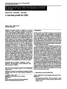
We use a communication system of a C4I complex to illustrate the concepts explained in this paper. Typically a C4I complex is comprised of a number of interacting elements and these elements are connected through a communication subnet. The communication subnet is a vital element for the success of the mission in a network centric warfare scenario. Similarly the network plays an important role in the maintenance of the C4I software. Changes in the communication network due to technological advances and/or user requirements, cause changes in the C4I software. These changes may be very expensive in terms of reliability of the software. So, to isolate the C4I system from changes in the communication system, most of the C4I complexes use another subsystem to handle the realtime communication required for the mission as shown in the Fig 1. The major functions of the communication interface system are as follows: 1. Packetization and reassembly 2. Protocol conversion 3. Fault tolerance at media level 4. Session maintenance 5. Priority based on the type of the data 6. Security and authentication of data 7. Logging 8. Monitoring health of communication equipment 9. On-line status display and alerts
InterJRI Computer Science and Networking, Vol. 1, Issue 1, July 2009
Operator
Administration
Communicate Local Host
55
Local host
Authenticate
Monitor Health
ComnEqpt
Peer CI
Communicate Peer CI
Communicate Stdby CI
Stdby CI
Figure 1. Use Case Diagram for Communication Interface System