Hindawi Publishing Corporation International Journal of Antennas and Propagation Volume 2016, Article ID 2621862, 8 pages http://dx.doi.org/10.1155/2016/2621862
Research Article Design of UAVs-Based 3D Antenna Arrays for a Maximum Performance in Terms of Directivity and SLL Jesus Garza,1 Marco A. Panduro,2 Alberto Reyna,1 Gerardo Romero,1 and Carlos del Rio3 1
Unidad Acad´emica Multidisciplinaria Reynosa-Rodhe, Universidad Aut´onoma de Tamaulipas (UAT), Carretera Reynosa-San Fernando, 88779 Reynosa, TAMPS, Mexico 2 CICESE Research Center, Electronics and Telecommunications Department, Carretera Ensenada-Tijuana No. 3918, Zona Playitas, 22860 Ensenada, BC, Mexico 3 Universidad P´ublica de Navarra, Arrosadia Campus, UPNA, Pamplona, Spain Correspondence should be addressed to Marco A. Panduro;
[email protected] Received 25 April 2016; Revised 10 July 2016; Accepted 2 August 2016 Academic Editor: Christos Kalialakis Copyright © 2016 Jesus Garza et al. This is an open access article distributed under the Creative Commons Attribution License, which permits unrestricted use, distribution, and reproduction in any medium, provided the original work is properly cited. This paper presents a design of UAVs-based 3D antenna arrays for a maximum performance in terms of directivity and side lobe level (SLL). This paper illustrates how to model the UAVs formation flight using 3D nonuniform antenna arrays. This design of 3D antenna arrays considers the optimization of the positions of the antenna elements to model the UAVs formation flight. In this case, a disk patch antenna is chosen to be used as element in each UAV. The disk patch antenna is formulated by the well-known cavity model. The synthesis process is carried out by the method of Differential Evolution for Multiobjective Optimization (DEMO). Furthermore, a comparison of the performance of 3D nonuniform antenna arrays is provided with respect to the most conventional arrays (circular, planar, linear, and the cubic) for UAVs formation flight.
1. Introduction Unmanned Aerial Vehicles (UAVs) embrace applications of Precision Formation Flying (PFF) [1–3] in civil and military usages. Military users such as tactical units on patrol missions can apply micro UAVs for intelligence, surveillance, and reconnaissance tasks. UAVs own the capability of coordinated area surveillance. In civil applications UAVs are used in agricultural practices, police surveillance, pollution control, environment monitoring, and fighting fires [1, 3]. The main problem presented in UAVs applications is the limited range of operation for signal and power consumption. Many applications consider an omnidirectional antenna for UAVs communications. In this case, guaranteed quality communication is required to support formation control and a nonstop process of tracking and maintaining a chosen geometric shape [2]. The way to find a better communication is by utilizing antenna arrays. However, equipping UAVs with antenna arrays is impractical. This is because antenna arrays need a lot of space and energy consumption.
A possible solution to this problem would be to form an antenna array whose elements are the antennas on each of the UAVs in the cluster. In this situation, the UAVs would first share the information to be transmitted among each other and then perform data aggregation, compression, and additional processing such as feature extraction to condense the data as much as possible [4]. Following the additional processing, the UAVs would fly into a formation conducive to good array performance and then transmit together, using electromagnetic interference to focus their limited power in the direction of the intended receiver [4]. Not only does this have the advantage of combining their transmitted power, but it also improves the situation further by sending more of this power in the direction of the receiver, causing less waste. This property of antenna systems, called directivity, is the primary reason, beyond inefficiencies of very small antennas, why an antenna with large spatial extent has an advantage over a smaller one [4]. The idea of forming an antenna array from several vehicles has been explored in [4, 5]. However, a performance
2
International Journal of Antennas and Propagation
evaluation of the problem for UAVs, including an analysis of the expected performance in UAVs-based antenna arrays for a maximum performance in terms of directivity and side lobe level, is lacking. The UAVs formation flight could be modeled by using a chosen geometric shape such as a linear array, a planar array, and a 3-dimensional array. Linear [6, 7] and planar [8, 9] antenna arrays are the most studied and applied. However, the UAVs formation flight could maintain any geometric shape in space; that is, UAVs could take advantage from a 3D antenna array considering optimal positions for UAVs formation flight in order to have a maximum performance in terms of directivity and enlarging the range of operation. Communications at long range for UAVs could be improved by considering optimal positions for UAVs in a 3D nonuniform array (as flight formation group). This paper presents a design of UAVs-based 3D antenna arrays for a maximum performance in terms of directivity and side lobe level (SLL). This paper illustrates how to model the UAVs formation flight using 3D nonuniform antenna arrays. This design of 3D antenna arrays considers the optimization of the positions of the antenna elements to model the UAVs formation flight. In this case, a disk patch antenna is chosen to be used as element in each UAV. The disk patch antenna is formulated by the well-known cavity model [10]. The synthesis process is carried out by the method of Differential Evolution for Multiobjective Optimization (DEMO) [11–13]. Furthermore, a comparison of the performance of 3D nonuniform antenna arrays is provided with respect to the most conventional arrays (circular, planar, linear, and the cubic) for UAVs formation flight. The remainder of the paper is organized as follows. Section 2 states the antenna array design problem we are dealing with. Section 3 describes the evolutionary multiobjective optimization algorithm employed. Section 4 presents and discusses the simulation results. Finally, the summary and conclusions of this work are presented in Section 5.
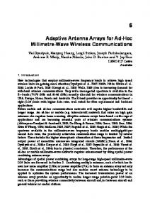
2. Problem Statement Consider a 3D antenna array of elements nonuniformly spaced on the space coordinates 𝑥𝑦𝑧, as shown in Figure 1. Please note that the radiation pattern is formed by each disk patch of each UAV. The radiation pattern for this array is given by [10] 𝑃 (𝜃, 𝜙) = 𝐺 (𝜃, 𝜙) 𝐴𝐹 (𝜃, 𝜙) , 𝑁𝐴
𝐴𝐹 (𝜃, 𝜙) = ∑ 𝐼𝑛 𝑒𝑗[𝑘(𝑥𝑛 sin 𝜃 cos 𝜙+𝑦𝑛 sin 𝜃 sin 𝜙+𝑧𝑛 cos 𝜃)] ,
(1)
𝑛=1
where 𝜆 is the signal wavelength; 𝑘 = 2𝜋/𝜆 is the phase constant; 𝜃 is the angle of a plane wave in the elevation plane; 𝜙 is the angle of a plane wave in the azimuth plane; (𝑥𝑛 , 𝑦𝑛 , 𝑧𝑛 ) represents the space coordinates of antenna element 𝑛, and (𝑥𝑛 , 𝑦𝑛 , 𝑧𝑛 ) is given by the separation between antenna elements.
z 𝜃
y
𝜙 x
Figure 1: UAVs-based 3D antenna array with nonuniform spacing.
The 𝐺(𝜃, 𝜙) term is the element pattern of a disk patch antenna modeled by the cavity model as follows [10]: 𝐸𝜙 = cos 𝜃 sin 𝜙 [𝐽0 (𝑘𝑎 sin 𝜃) + 𝐽2 (𝑘𝑎 sin 𝜃)] , 𝐸𝜃 = cos 𝜙 [𝐽0 (𝑘𝑎 sin 𝜃) − 𝐽2 (𝑘𝑎 sin 𝜃)] ,
(2)
𝐺 (𝜃, 𝜙) = √𝐸𝜃 2 + 𝐸𝜙 2 . The terms 𝐸𝜃 and 𝐸𝜙 are the normalized pattern components at the fundamental mode 𝑇𝑀11 of each disk patch antenna via the well-known cavity model, where 𝑎 is the radius of the patch at the resonance frequency. 𝐽0 and 𝐽2 are Bessel functions of the zero and second order, respectively. The antenna elements installed in UAVs will be of low directivity with omnidirectional pattern. However, the radiating characteristics of the array will prevail. This is because the relative position of the different UAVs defines the steering vector not the antenna elements. Comparing the individual pattern of each UAV considering coupling with the UAV structure (electric motors or electronics) could be hard work and basis for another study or paper and could be integrated with the results of this research. The idea of this paper is to demonstrate the possibility of generating 3D arrays able to focus their limited power in the direction of the intended receiver. In this case, the cavity model is well suited for circular patches. A full wave analysis would require an antenna model and a UAVs model taking a high volume into account for simulating. This makes it difficult for any method. A full wave simulation considering the antenna model and a UAVs model could be integrated with the results of this research. However, this is out of the scope of this paper. The amplitude excitations are set to be equal in the array; that is, uniform amplitude excitation is utilized. In this case, the positions of the antenna elements (𝑥𝑛 , 𝑦𝑛 , 𝑧𝑛 ) or (UAVs positions) are given by the separation between antenna elements in the axes 𝑥, 𝑦, and 𝑧.
International Journal of Antennas and Propagation
3
Therefore, the decision variables for this design problem are the positions of the antenna elements arranged in three vectors of real numbers as follows: x = [𝑥1 , . . . , 𝑥𝑛 , . . . , 𝑥𝑁𝐴 ] , y = [𝑦1 , . . . , 𝑦𝑛 , . . . , 𝑦𝑁𝐴 ] ,
(3)
z = [𝑧1 , . . . , 𝑧𝑛 , . . . , 𝑧𝑁𝐴 ] . The objective functions of this design problem can be formulated as follows: 𝑓1 = SLLmax (x, y, z) , 𝑓2 =
(4)
1 , DIR (x, y, z)
where SLLmax is the maximum side lobe level attained in 𝜙 = [0, 2𝜋] and 𝜃 = [0, 𝜋] and DIR represents the directivity of the radiation pattern. The directivity of the radiation pattern is given by the next expression [13]: DIR =
4𝜋𝑃 (𝜃, 𝜙)max
.
3. The Multiobjective Evolutionary Optimization Algorithm The optimization process is carried out by the DEMO algorithm due to its effectiveness in antenna arrays design [12]. DEMO is an optimization approach based on the classical method of Differential Evolution (DE) [14] combined with the mechanisms of Pareto-based ranking and crowding distance sorting, employed in the literature of evolutionary algorithms for multiobjective optimization. In order to resolve the proposed synthesis design problem, the DEMO algorithm was selected based on the performance comparison of NSGA-II [15], EM-MOPSO [16], and DEMO variants [11] made by Panduro et al. [12] for the design of concentric rings antenna arrays. The results of that performance comparison showed that the variants of DEMO/parent and DEMO/closest/dec found better nondominated solutions than the other algorithms. Please note that the authors do not claim that DEMO is the best algorithm for this design problem. The finding of the best optimization algorithm for designing an antenna array remains as an open problem. The used DEMO/parent is described as follows [11]:
(5)
(1) Evaluate the initial population P of random individuals.
Based on these definitions the objective functions can be written as the minimization of the maximum side lobe level (𝑓1 ), and in the second component it is the maximization of the directivity (𝑓2 ). Then the problem can be formulated as
(2) While stopping criterion is not met, do the following:
𝜋,2𝜋
∬𝜃=0,𝜙=0 𝑃 (𝜃, 𝜙) sin 𝜃 𝑑𝜃 𝑑𝜙
Minimize
(𝑓1 , 𝑓2 )
Subject to
x, y, z ∈ Λ,
(6)
where Λ contains values of x, y, and z to avoid a possible UAVs crash on the array. In this case, to avoid a possible UAVs crash on the array, the minimal Euclidean distance between each pair of UAVs is restricted to 2 𝜆 on a cubic space of 10 𝜆. The relations between the decision variables x, y, and z with 𝑓1 , 𝑓2 are not trivial, but highly nonlinear. Since the UAVs formation flight could maintain any geometric shape in space, the beam steering of the 3D antenna array is not considered in this design problem; that is, the natural response of the array is considered to be optimized. Shadowing effect in a 3D antenna array is highly probable to occur as UAVs not collocated in the same plane will be affected by the UAVs located in the planes below looking in the horizon of the array. Also diffraction will occur in both the UAVs directly affecting the installed element pattern (with the possibility of a flower pattern with zeros in the visible region under certain conditions) and from UAVs that are on the horizon of the UAV 3D array main beam. Diffraction and reflection will create more problems as they will give arbitrary installed element patterns. The shadowing effect would require a deeper study and could be integrated with the results of this research. The next section presents the multiobjective evolutionary optimization algorithm to be applied to this design problem.
(a) for each individual 𝑃𝑖 (𝑖 = 1, . . . , popSize) from P repeat: (i) create candidate 𝐶 from 𝑃𝑖 ; (ii) evaluate candidate; (iii) if the candidate dominates the parent, the candidate replaces the parent; (iv) if the parent dominates the candidate, the candidate is discarded. Otherwise, the candidate is added to the population; (b) if the population has more than popSize individuals, truncate it by sorting the individuals with nondominated sorting and then evaluating the individuals of the same front with the crowding distance metric; (c) randomly enumerate the individuals in P. For the candidate creation, the DE scheme DE/rand/1/bin [11–13] is used, and the procedure for this scheme is described as follows: (1) Randomly select three individuals 𝑃𝑖1 , 𝑃𝑖2 , 𝑃𝑖3 from P, where 𝑖, 𝑖1 , 𝑖2 , and 𝑖3 are pairwise different. (2) Calculate candidate 𝐶 as 𝐶 = 𝑃𝑖1 +𝐹×(𝑃𝑖2 −𝑃𝑖3 ), where 𝐹 is a scaling factor. (3) Modify the candidate by binary crossover with the parent using a crossover probability of 𝑝𝑐 . The immediate replacement of the parent individual with the candidate that dominates it emphasises elitism within reproduction. This provides a better convergence to the true
4
International Journal of Antennas and Propagation Begin Generate an initial population 𝒫 of size popSize Evaluation of the population i = 1; ITE = 1
Create candidate C from Pi C = Pi1 + F × (Pi2 − Pi3 ) Apply crossover to C from Pi with probability pc Evaluation of candidate C (Compute of1 and of2 ) C(of1 , of2 ) < Pi (of1 , of2 )
Pi = C i= i+1
C(of1 ) < Pi (of1 ) or C(of2 ) < Pi (of2 )
Add C to 𝒫 i= i+1
Discard C i= i+1
i > popSize
|𝒫| > popSize
Truncate 𝒫 to |𝒫| = popSize Randomly enumerate individuals of 𝒫 ITE = ITE + 1
ITE = total_ITE
End
Figure 2: Flow chart for the implemented DEMO/parent procedure.
Pareto front. And the use of nondominated sorting and crowding distance metric in truncation of the extended population stimulates the uniform spread of solutions, finding as diverse nondominated solutions as possible [11]. Therefore, the procedure of the DEMO/parent process for our synthesis problem is described in Figure 2. Each individual is in general represented by three vectors of real
numbers (positions of the antenna elements in the axes 𝑥, 𝑦, and 𝑧). The stopping criterion is on the total number of iterations. In this case, the initial solutions do not affect critically the algorithm result. The interesting aspect of this system is that if the synchronization of all elements is in phase, all the UAVs can modify slightly their positions (within the feasible space)
International Journal of Antennas and Propagation
5
Side lobe level relative to the main beam (dB)
0 −5 −10 −15 −20 −25 −30 −35 −40
0
20
40
60
80
100
120
140
160
180
𝜃∘ DEMO NSGA-II
Figure 3: Final solution of the array factor obtained by DEMO/parent in comparison with respect to NSGA-II.
finding the necessary positions in points close to the initial solutions. The results of using this evolutionary multiobjective optimization algorithm for the design of UAVs-based 3D antenna arrays are described in the next section.
4. Simulation Results The DEMO/parent was implemented to study the behavior of the radiation pattern for UAVs-based 3D antenna arrays. The behavior of the radiation pattern is analyzed for 𝑁𝐴 = 8 antennas. For this array configuration, the minimal Euclidean distance between each pair of UAVs is restricted to 2 𝜆 on a cubic space of 10 𝜆; that is, the positions of the antenna elements are considered to be 0 𝜆 ≤ 𝑥𝑛 ≤ 10 𝜆, 0 𝜆 ≤ 𝑦𝑛 ≤ 10 𝜆, 0 𝜆 ≤ 𝑧𝑛 ≤ 10 𝜆. The operation frequency is 2.4 GHz. Since the UAVs formation flight could maintain any geometric shape in space, the beam steering of the 3D antenna array is not considered in this design problem; that is, the natural response of the array is considered to be optimized in the cut of 𝜙 = 0∘ . In the DEMO algorithm the value of 𝐹 is set to 0.5. The stopping criterion is met when a number of iterations ITE = 1000 are reached. The crossover probability is set to 𝑝𝑐 = 1.0. The population size is set to popSize = 200. The algorithm was executed 5 times and the consolidated front for each run is considered. Figure 3 shows the final solution of the array factor obtained by DEMO/parent. The array factor response of the DEMO/parent algorithm is compared with respect to a well-known algorithm the NSGA-II [15]. DEMO/parent outperforms the array factor characteristics generated by the NSGA-II by providing a better solution in terms of the SLL and directivity. In this case, the solution of DEMO provides a DIR = 9.31 dB and SLL = 4.43 dB, while NSGA-II provides a DIR = 8.92 dB and SLL = 2.77 dB. The average computation time for the 5 runs of DEMO/ parent is approximately 455 minutes for 1000 iterations employed. The DEMO/parent algorithm was implemented in Matlab in a PC with a Processor Xeon 3.20 GHz (28 GB
Table 1: Comparison of the performance in terms of the SLL and DIR of 3D nonuniform antenna array with respect to the most conventional arrays for UAVs formation flight. Array configuration Directivity (dB) Side lobe level (dB) 3D nonuniform (DEMO) 9.31 −4.43 3D nonuniform (NSGA-II) 8.92 −2.77 Cubic 8.91 −0.24 Linear 9.29 −2.74 Circular 8.16 −0.46 Planar 9.12 −0.47
of RAM 64 bits). In this case the time for NSGA-II is 411 minutes, very similar to DEMO algorithm. In order to make a comparison of the performance of 3D nonuniform antenna array with respect to the most conventional arrays for UAVs formation flight, Figures 4(a)–4(e) illustrate design examples obtained for a planar array (Figure 4(a)), a linear array (Figure 4(b)), a circular array (Figure 4(c)), a cubic array (Figure 4(d)), and the case of 3Dnonuniform optimized by DEMO/parent (Figure 4(e)). Each design example uses 8 antenna elements with a maximum aperture or maximum dimension of 10 𝜆 for each array. The response of the radiation pattern for the design examples (illustrated in Figures 4(a)–4(e)) is shown in Figures 5(a)–5(d). As it can be seen in Figures 5(a)–5(d) the response of the radiation pattern for the 3D nonuniform array provides a better performance in terms of the side lobe level and directivity with respect to the most conventional arrays for UAVs formation flight. The values of the SLL and DIR of 3D nonuniform antenna array and the conventional arrays for UAVs formation flight are shown in Table 1. As shown in Table 1, the 3D nonuniform antenna array optimized by DEMO/parent outperforms the array factor characteristics generated by the NSGA-II and the cubic, linear, circular, and planar array configurations. Certainly, if long distances between antenna elements are considered, any relative movement could have an effect. However, a nonuniform array distribution provides advantages to
6
International Journal of Antennas and Propagation
10 9 8 7 6 z 5 4 3 2 1 0 0
12
10 9 8 7 6 z 5 4 3 2 1 0 0 34 x
56
9 10 7 8 6 7 8 4 5 2 3 y 9 10 0 1
12 34
56 6 7 4 5 7 8 x 3 2 9 y 10 0 1
(a)
10 8 9
(b)
10 9 8 7 6 z 5 4 3 2 1 0 01 2 3 4
9 10 7 8 56 6 4 5 7 8 x 2 3 y 910 1 0
10 9 8 7 6 z 5 4 3 2 1 0 01
2
34
7 56 5 6 7 8 3 4 x 2 9 10 y 0 1
(c)
10 9 8 7 6 z 5 4 3 2 1 0 0
10 8 9
(d)
1
23
9 10 45 7 8 6 6 7 4 5 89 x 2 3 y 1 10 0 (e)
Figure 4: Distribution of 8 antennas on five different array configurations for UAVs formation flight: (a) planar, (b) linear, (c) circular, (d) cubic, and (e) 3D nonuniform optimized by DEMO/parent.
International Journal of Antennas and Propagation
7 0 Side lobe level relative to the main beam (dB)
Side lobe level relative to the main beam (dB)
0 −10 −20 −30 −40 −50 −60 −70 −80
−80
−60
−40
−20
0
20
40
60
80
−10 −20 −30 −40 −50 −60 −70
−80
−60
−40
−20
𝜃 (deg.) Circular array DEMO optimized
−60
−40
−20
Side lobe level relative to the main beam (dB)
40
60
80
20
40
60
80
(b)
Side lobe level relative to the main beam (dB) −80
20
Cubic array DEMO optimized
(a)
0 −10 −20 −30 −40 −50 −60 −70 −80 −90 −100
0 𝜃 (deg.)
0
20
40
60
80
0 −5 −10 −15 −20 −25 −30 −35 −40 −45 −50 −55
−80
−60
−40
−20
𝜃 (deg.) DEMO optimized Linear array
0 𝜃 (deg.)
DEMO optimized Planar array
(c)
(d)
Figure 5: Comparison of the gain or normalized radiation pattern of 3D nonuniform antenna array with respect to the most conventional arrays for UAVs formation flight: (a) 3D array optimized versus uniform circular array, (b) 3D array optimized versus cubic array, (c) 3D array optimized versus uniform linear array, and (d) 3D array optimized versus uniform planar array.
the system; that is, the possible errors are individual and their consequences too by limiting the effect of each element to its particular contribution, 1/8 of the received power for this study case. In this case, if the synchronization is achieved in phase (the simplest case), all the UAVs transmit in the same time in a synchronous way. The determination of the relative position will determine the coherent sum in the adequate direction. Once the positions are determined, the control algorithm employed or the concrete location method will determine the goodness of the array. It is clear that the correct synchronization will be more critical for disperse UAVs, and the pattern of the array will be more unstable, although it must be considered that each element contributes with a part to that stability. From the results shown previously, a perspective is illustrated for designing 3D nonuniform antenna arrays for UAVs formation flight using DEMO. The evolutionary multiobjective algorithm efficiently computes a set of antenna element positions in order to provide a radiation pattern with minimum SLL and maximum directivity. The optimized design case can be used as a UAVs formation flight for
long distances communications. The maximum performance in terms of directivity and SLL could enlarge the range of operation for UAVs communications. Communications at long range for UAVs could be improved by design of 3D nonuniform array as flight formation group.
5. Conclusions This paper illustrates how to model the design of UAVsbased 3D antenna arrays for a maximum performance in terms of directivity and SLL. Simulation results reveal that the design of 3D antenna array with positions of eight antenna elements obtained by DEMO/parent outperforms the array factor characteristics generated by the NSGA-II by providing a better solution in terms of the SLL and directivity. In this case, the solution of DEMO provides a DIR = 9.31 dB and SLL = 4.43 dB, while NSGA-II provides a DIR = 8.92 dB and SLL = 2.77 dB. Furthermore, the 3D nonuniform antenna array optimized by DEMO/parent outperforms the array factor characteristics generated by the NSGA-II and the cubic, linear, circular, and planar array configurations. In this case, these values of SLL and directivity for the optimized design
8 case are achieved with very similar values of aperture (10 𝜆) with respect to the other array configurations. The optimized design case can be used as a UAVs formation flight for enlarging the range of operation for UAVs communications as well as improving performance in coordinated flight formations without compromising the energy and weight load of the UAVs.
Competing Interests The authors declare that they have no competing interests.
References [1] A. B¨urkle, F. Segor, and M. Kollmann, “Towards autonomous micro UAV swarms,” Journal of Intelligent & Robotic Systems, vol. 61, no. 1–4, pp. 339–353, 2011. [2] L. P. Clare, J. L. Gao, E. H. Jennings, and C. Okino, “A network architecture for precision formation flying using the IEEE 802.11 MAC protocol,” in Proceedings of the IEEE Aerospace Conference, pp. 1335–1347, IEEE, Big Sky, Mont, USA, March 2005. [3] A. Sivakumar and C. K.-Y. Tan, “UAV swarm coordination using cooperative control for establishing a wireless communications backbone,” in Proceedings of the 9th International Joint Conference on Autonomous Agents and Multiagent Systems (AAMAS ’10), vol. 3, pp. 1157–1164, 2010. [4] S. H. Breheny, R. D’Andrea, and J. C. Miller, “Using airborne vehicle-based antenna arrays to improve communications with UAV clusters,” in Proceedings of the 42nd IEEE Conference on Decision and Control, vol. 4, pp. 4158–4162, IEEE, 2003. [5] S.-S. Jan and P. Enge, “Using GPS to synthesize a large antenna aperture when the elements are mobile,” in Proceedings of the National Technical Meeting of The Institute of Navigation, Anaheim, Calif, USA, 2000. [6] F. J. Ares-Pena, J. A. Rodriguez-Gonzalez, E. Villanueva-Lopez, and S. R. Rengarajan, “Genetic algorithms in the design and optimization of antenna array patterns,” IEEE Transactions on Antennas and Propagation, vol. 47, no. 3, pp. 506–510, 1999. [7] M. G. Bray, D. H. Werner, D. W. Boeringer, and D. W. Machuga, “Optimization of thinned aperiodic linear phased arrays using genetic algorithms to reduce grating lobes during scanning,” IEEE Transactions on Antennas and Propagation, vol. 50, no. 12, pp. 1732–1742, 2002. [8] C. Rocha-Alicano, D. Covarrubias-Rosales, C. Brizuela-Rodriguez, and M. Panduro-Mendoza, “Differential evolution algorithm applied to sidelobe level reduction on a planar array,” AEU—International Journal of Electronics and Communications, vol. 61, no. 5, pp. 286–290, 2007. [9] R. L. Haupt, “Thinned arrays using genetic algorithms,” IEEE Transactions on Antennas and Propagation, vol. 42, no. 7, pp. 993–999, 1994. [10] K. F. Lee, K. M. Luk, K. M. Mak, and S. L. S. Yang, “On the use of U-slots in the design of dual-and triple-band patch antennas,” IEEE Antennas and Propagation Magazine, vol. 53, no. 3, pp. 60– 74, 2011. [11] T. Robiˇc and B. Filipiˇc, “DEMO: differential evolution for multiobjective optimization,” in Evolutionary Multi-Criterion Optimization, C. A. C. Coello, A. H. Aguirre, and E. Zitzler, Eds., vol. 3410 of Lecture Notes in Computer Science, pp. 520–533, Springer, Berlin, Germany, 2005.
International Journal of Antennas and Propagation [12] M. A. Panduro, C. A. Brizuela, J. Garza, S. Hinojosa, and A. Reyna, “A comparison of NSGA-II, DEMO, and EM-MOPSO for the multi-objective design of concentric rings antenna arrays,” Journal of Electromagnetic Waves and Applications, vol. 27, no. 9, pp. 1100–1113, 2013. [13] C. A. Balanis, Antenna Theory: Analysis and Design, John Wiley & Sons, New York, NY, USA, 2016. [14] R. Storn and K. Price, “Differential evolution—a simple and efficient heuristic for global optimization over continuous spaces,” Journal of Global Optimization, vol. 11, no. 4, pp. 341– 359, 1997. [15] K. Deb, S. Agrawal, A. Pratap, and T. Meyarivan, “A fast elitist non-dominated sorting genetic algorithm for multi-objective optimization: NSGA-II,” in Parallel Problem Solving from Nature PPSN VI, Springer, Berlin, Germany, 2000. [16] M. Janga Reddy and D. Nagesh Kumar, “An efficient multiobjective optimization algorithm based on swarm intelligence for engineering design,” Engineering Optimization, vol. 39, no. 1, pp. 49–68, 2007.
International Journal of
Rotating Machinery
Engineering Journal of
Hindawi Publishing Corporation http://www.hindawi.com
Volume 2014
The Scientific World Journal Hindawi Publishing Corporation http://www.hindawi.com
Volume 2014
International Journal of
Distributed Sensor Networks
Journal of
Sensors Hindawi Publishing Corporation http://www.hindawi.com
Volume 2014
Hindawi Publishing Corporation http://www.hindawi.com
Volume 2014
Hindawi Publishing Corporation http://www.hindawi.com
Volume 2014
Journal of
Control Science and Engineering
Advances in
Civil Engineering Hindawi Publishing Corporation http://www.hindawi.com
Hindawi Publishing Corporation http://www.hindawi.com
Volume 2014
Volume 2014
Submit your manuscripts at http://www.hindawi.com Journal of
Journal of
Electrical and Computer Engineering
Robotics Hindawi Publishing Corporation http://www.hindawi.com
Hindawi Publishing Corporation http://www.hindawi.com
Volume 2014
Volume 2014
VLSI Design Advances in OptoElectronics
International Journal of
Navigation and Observation Hindawi Publishing Corporation http://www.hindawi.com
Volume 2014
Hindawi Publishing Corporation http://www.hindawi.com
Hindawi Publishing Corporation http://www.hindawi.com
Chemical Engineering Hindawi Publishing Corporation http://www.hindawi.com
Volume 2014
Volume 2014
Active and Passive Electronic Components
Antennas and Propagation Hindawi Publishing Corporation http://www.hindawi.com
Aerospace Engineering
Hindawi Publishing Corporation http://www.hindawi.com
Volume 2014
Hindawi Publishing Corporation http://www.hindawi.com
Volume 2014
Volume 2014
International Journal of
International Journal of
International Journal of
Modelling & Simulation in Engineering
Volume 2014
Hindawi Publishing Corporation http://www.hindawi.com
Volume 2014
Shock and Vibration Hindawi Publishing Corporation http://www.hindawi.com
Volume 2014
Advances in
Acoustics and Vibration Hindawi Publishing Corporation http://www.hindawi.com
Volume 2014