WSEAS TRANSACTIONS on COMPUTER RESEARCH
Artis Teilans, Arnis Kleins, Yuri Merkuryev and Andris Grinbergs
Design of UML models and their simulation using ARENA ARTIS TEILANS and ARNIS KLEINS Exigen Services DATI 17a Ganibu Dambis, LV-1045, Riga LATVIA
[email protected] [email protected] YURI MERKURYEV and ANDRIS GRINBERGS Department of Modelling and Simulation Riga Technical University 1 Kalku Street, LV-1658, Riga LATVIA
[email protected] [email protected] http://www.itl.rtu.lv/mik/ymerk.html Abstract: - While developing new business systems and reengineering already existing ones, many organizations use the Unified Modelling Language (UML) to design a system’s structure and describe system’s behaviour. In spite of describing system’s behaviour with the UML model, the model itself is static. UML does not provide a possibility of running the model and studying the system’s behaviour. In such a situation the necessity arises to simulate the UML model. To provide that possibility, the designed UML diagrams could be transformed into a simulation model to be run within a specialized simulation environment. The paper discusses a transformation of that kind using the Arena simulation environment. In order to design UML models, a meta-modelling approach is explored. Key-Words: - Simulation, Arena, UML modelling, transformation of models, meta-model widely used at systems development or enhancement phases. Today two large but separate modeller communities exist. The first community uses UML modelling tools, while the second one uses simulation languages and specialised simulation software tools for the same systems modelling. The authors of this paper also represent both communities. This paper introduces a work, which tries to merge both systems modelling approaches, UML modelling and systems simulation. In the course of the work it was tested how to transform UML models or parts of these models into models for specialised simulation environments. In particular, ARENA [2] was used as a simulation environment for this task. The third author of this paper has worked out a Master’s thesis [5], which includes the research prototype for automatic transformation of UML diagrams into a simulation model. It ensures that the developer of simulation model does not need to research the system for the second time, because the UML model of system has already been created. Such an approach saves a lot of time. Moreover, users can easily initiate automatic creation of a simulation model with a simple and understandable tool.
1 Introduction UML (Unified Modelling Language) belongs to the group of graphical languages. Initially UML was built for information systems modelling to facilitate the development and maintenance processes. Nowadays the usage of UML is broadened. This language is used for building business models, which exceed the initial task of modelling of information systems. The work at creation of the Unified Modelling Language started in 1996 and is still being continued. Any interested person can have a free access to the UML 2.0 specification on the Object Management Group’s web page [1, 6]. Simulation is the process of modelling a system and experimentation with a model of the system. Simulation is imitation of the operation of the system over time, considering the influence of external and internal stochastic factors. Usually simulation is used for deeper investigation of the modelled system and forecasting system’s behaviour in different circumstances. Simulation provides the possibility of choosing the right system’s design strategy, optimise parameters of the system and identify faults. Simulation is useful for personal training as well. As regards system modelling, both of the approaches, UML modelling and simulation, are ISSN: 1991-8755
67
Issue 1, Volume 3, January 2008
WSEAS TRANSACTIONS on COMPUTER RESEARCH
Artis Teilans, Arnis Kleins, Yuri Merkuryev and Andris Grinbergs
A similar approach is described in [4], where a UML model representing the simulation program is created and can be further simulated. However, the approach described in the present paper can be used in the case when a UML model is constructed before the simulation need appears and modeller has to perform the simulation.
Model Driven Architecture (MDA). Supplementing graphical notations with terms such as class, component, generalization, aggregation and behaviour, helps save system designer’s time for system architectural tasks and design. UML allows one to introduce new graphical elements and terms, specific for particular problem domain, and create domain specific profiles and stereotypes. A UML model consists of a set of diagrams. A diagram is a partial representation of the model. A system model could be divided into three parts. The first part is a functional model, which reflects functionality of a system from the system user’s point of view. This kind of model is constructed using Use Case diagrams.
2 Modelling tools and models As mentioned in the previous chapter, the main problem in system engineering is two separate modeller communities, where the first is using UML modelling tools while the second works with specialised simulation languages and simulation environments.
Fig. 1. Hierarchy of UML diagrams The second part of the UML model reflects the hierarchical structures of a system, using objects, attributes, operations and relations between objects. This part includes Class diagrams. And finally, the dynamical model reflects internal behaviour of the system. A model of that kind is constructed using Activity, State, Sequence and Collaboration diagrams. Models could be created using UML modelling tools. Nowadays, plenty of such software tools exist that support UML model building and differ mainly in price and popularity. UML 2.0 consists of 13 types of diagrams. For better understanding, the diagrams could be ordered as a hierarchy (see Fig. 1) [1]. A system model to be created with UML language should not necessarily contain all diagrams. For
2.1 UML tools and models UML modelling describes the system’s structure and behaviour. This language consists of graphical notations called diagrams and builds up an abstract model of a system. The UML standard is maintained by OMG (Object Management Group). In the beginning, UML was built for specification visualization and documentation of IT systems development. Nowadays usages of UML are not limited only to tasks of software engineering. UML is also used for business process modelling and for the development of systems which are not pure information systems. Modelling with UML promotes model-driven technologies, such as Model Driven Development (MDD), Model Driven Engineering (MDE) and ISSN: 1991-8755
68
Issue 1, Volume 3, January 2008
WSEAS TRANSACTIONS on COMPUTER RESEARCH
Artis Teilans, Arnis Kleins, Yuri Merkuryev and Andris Grinbergs
example, creating Information System vision model or requirement specification, it is enough for system analyst to create Use Case and Activity diagrams.
company, computer system hardware or software. An Actor is a role of object outside of a system that interacts directly with it. An Actor could be a special
View Contains
IsSpecial
Is part of
Contains
IsGeneral
IsIncluded
Actor
Include
Is part of
Use Case Communicate
Communicate
Extend
IsExtended Has scenario Is Followed By
Is Preceeded By
Activity
Receives What
Sends What
Is Scenario Of
Is Performed By
Performs
Has scenario
Scenario
Is Scenario Of
Has Input Condition Has Output Condition Is Received By
Is Sent By
Is Output Condition of
Object
Is Input Condition of
Condition
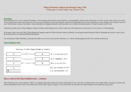
Fig. 2 Object types and relationships for UML modelling Use Case diagram answers a question – what a system does. Activity diagrams describe scenarios of every Use Case, i.e., Business processes. Due to that, of the set of UML diagrams depicted in Fig.1, this work uses only Use case and Activity diagrams. Particularly for the simulation activities only activity diagrams are used. In order to develop UML diagrams, a structure of the considered system should be described. This structure is defined by a meta-model. It consists of entities and relationships. Presented here information will organize all important facts from analysis stage according to the meta-model (Fig. 2). The capture of objects can be performed in any sequence without regarding hierarchy. The object hierarchy and communication paths are entered later by defining relationships between objects. Let us take a closer look to the meta-model. An Actor might be a person, a ISSN: 1991-8755
case described by Is Special relationship or generalization described by Is General relationship. Use Case represents modelled system behaviour under various conditions as it responds to actor communicating the system to yield an observable result of value to an actor. Scenarios describe different sequences of system behaviour depending on the particular requests. An activity is a state of doing something. It could be real-world process or software routine. Activities are performed according to scenarios. The Use case groups together those different scenarios. Activity could be preceded and/or followed by another activity. Activities could be forked to initiate parallel processing and then joined afterwards, or conditionally branched and merged. Activity could give control to another activity and also passing an Object. Activity could be atomic (action) or could be complex consisting of
69
Issue 1, Volume 3, January 2008
WSEAS TRANSACTIONS on COMPUTER RESEARCH
Artis Teilans, Arnis Kleins, Yuri Merkuryev and Andris Grinbergs
Typical modelling activities include: • Analysis of various types of manufacturing systems containing material flow control
several another activities (actions) described in scenario. This is reflected in the model by Has Scenario / Is Scenario Of relationship. It is
Fig. 3 Model in the Arena simulation environment components; • Analysis of complex system services and control; • Supply chain analysis including an analysis of transportation, storing and logistics systems; • Forecasting the system behaviour based on resource capacity, process cycle timing and expenses; • Identifying bottlenecks, for example, forming queues and resource overloading; • Planning personal, equipment and material provision. Arena offers: • Imitation of the system behaviour in the future; • Achieving an understanding of the impact of complex variables on the modelled system; • Identification of possibility of the system performance optimisation; • Animation of operating model; • Comparing alternatives of different realisations of the system;
described by Is Received / Is Sent and Sends What / Receives What relationships. Use Case could consist of another Use Cases by using Include / Is Included relationship. If Use case is specialised case of another Use Case, it could be depicted by Extends / Is Extended relationship. After all meta-model elements are defined, the system model is completed. Then the next step is development of a related simulation model that will be considered in the following chapters.
2.2 ARENA simulation environment This kind of modelling tools is used by the second large community of system modellers. Arena is offered by Rockwell Software Inc. [2]. Arena is based on the SIMAN simulation language (see Fig. 3). It can be used for simulation of discrete and continuous systems, for simulation in manufacturing, supply chain management, logistics, storing and other processes. Using simulation an impact of different factors on the modelled system could be analysed. Arena ensures a high degree of flexibility, various facilities for models of any level of complexity. ISSN: 1991-8755
70
Issue 1, Volume 3, January 2008
WSEAS TRANSACTIONS on COMPUTER RESEARCH
Artis Teilans, Arnis Kleins, Yuri Merkuryev and Andris Grinbergs
Model elements of the Arena model are grouped and placed in panels. During model building process, modules from toolbox window can be selected and placed in the model, which are graphically drawn as boxes of different shape, and represent steps and logic of the simulated process. Modules are connected with connection lines, which determine the flow of entities in the model.
Arena provides modellers with a set of statistical reports about processed entities, queues and technological activities, etc. It has a well designed interface with Microsoft Office software. Fragments of code in MS Visual Basic can be embedded into the model. Arena allows one to export/import data from/to MS Access and Excel data tables. It supports a special shape of MS Visio diagrams as well.
Fig. 4 Library. Example of UML Activity diagram.
ISSN: 1991-8755
71
Issue 1, Volume 3, January 2008
WSEAS TRANSACTIONS on COMPUTER RESEARCH
Artis Teilans, Arnis Kleins, Yuri Merkuryev and Andris Grinbergs
Fig. 5 Library. Example of ARENA simulation model. 1. Make the syntax and semantic analysis of the activity diagram. Reconstruct Activity diagram as a flat table that contains all elements and connectors of the diagram. 2. Identify logical mistakes in the diagram, for example, missing start element, or facts that in an activity diagram elements from other UML diagrams are used, since it is unknown here how to transform elements from other diagrams. This step prepares a mapping between elements of UML Activity diagram and elements of ARENA models. 3. Create an ARENA model from the modules identified in the first step. For each module assign default values of attributes. These values can be changed during simulation experiments.
3 Transformation of models Of the set of UML diagrams, the present work uses only Activity diagrams for generating simulation models. The process of simulation proceeds in three steps. In the first step UML activity diagrams are transformed into a model of the Arena simulation environment. In the second step, simulation parameters, such as time of activities, probability of process branching, stochastic values of variables, etc. are tuned. And finally, the third step is to run simulation experiments.
3.1 Transformation algorithm Transformations of models are realised by the following algorithm: ISSN: 1991-8755
72
Issue 1, Volume 3, January 2008
WSEAS TRANSACTIONS on COMPUTER RESEARCH
3.2
Artis Teilans, Arnis Kleins, Yuri Merkuryev and Andris Grinbergs
simulation model builder, ARENA from Rockwell Software Inc. is employed. Internal file formats to solve task for exchanging data between the model transformation steps are Rational Rose petal file (ptl) and Microsoft Excel table (xls). Using semantic analysis of UML activity diagram, the authors define the mapping between elements of ARENA model and elements of UML activity diagram. UML is a well documented standard. Nevertheless, during UML modelling modellers introduce significant enhancements; sometimes they mix elements between different types of diagrams. Such a free interpretation of UML standards requires strong syntax and semantics analysis to provide automatic universal transformations of models. Any non-standard constructions in diagrams cannot be transformed and simulated. In this work the authors have found a solution for automatic transformation of UML models into the simulation models, where simulation model is constructed using UML activity diagrams. The authors continue this research work, because the UML standard includes 12 more diagram types, such as class diagrams, sequence and collaboration diagrams, etc. One more direction for future research is studying how to include various stochastic and deterministic parameters for simulation into UML models.
Research prototype and example
During the development of research prototype the authors were looking for different UML models in the Internet public area. These models were used to approbate the generation of simulation models. One of the models was borrowed from [3]. This is a books library. The model consists of one UML Activity diagram (see Fig. 4 and 5). This diagram model represents working processes of the library in detail. The process begins with arrival of visitors at the library. A visitor who is not registered in the library is channelled to the registration area for preparing the agreement document. At this point the visitor makes a decision regarding further activities. The visitor can borrow a book if he knows the exact title or can perform a title search. If the visitor has decided to search for the book, he should go to the corridor. And again in the case when the terminal is busy, the visitor uses adequate folder and search for a title in paper cards. After that, selection should be placed in the lending list. In such a manner, by using folders the visitor can select as many titles as he needs. After the selection is completed, the visitor should decide whether or not to borrow books and leave the library. The process is similar when searching is provided through library terminal. If the terminal is available, the visitor should log in, should select the search menu and should enter search criteria. The result is a list of available titles. The list can be revised or printed out. Searching process can be repeated until all of the necessary titles are worked out by the visitor. And again, at this point visitor should decide whether or not to borrow the books selected. When a list of books is not empty, the visitor is channelled to landing place, otherwise the process goes to finish. At landing place the visitor can ask for recommendations or annotations. And finally, the visitor presents library card and the borrowed books are recorded on visitor’s name.
References: [1] UML Superstructure Specification, v2, Object Management Group. 2004 [2] Arena User's Guide. Rockwell Software Inc. USA, WI, Milwaukee: Rockwell Software Inc., 2005 [3] Library Model. http://odl-skopje.etf.ukim.edu. mk/uml-help/html/05day2.html [4] Bernd Page, Wolfgang Kreutzer. The Java Simulation Handbook. Simulating Discrete Event Systems with UML and Java, Shaker Verlag Aachen, 2005 [5] Andris Grinbergs. Transforming UML Diagrams for Usage in Simulation Tools. Master Thesis, Riga Technical University, 2007. (In Latvian) [6] Doug Rosenberg, Matt Stephens. Use Case Driven Object Modeling with UML: Theory and Practice. Apress, 2007
4 Conclusions Of the UML models that were transformed into the simulation program, an activity diagram was used as a model basis, because the structure of this type of diagrams is most similar to the simulation program. The common standard for the exchange of UML diagrams between the modelling tools is already designed by the industry. But practically the exchange is limited between the tools of different companies. Due to these limits, connectors for UML tool, simulation software and model transformer software were developed in this work. As an UML tool, Rational Rose from IBM Inc. is used, and as ISSN: 1991-8755
73
Issue 1, Volume 3, January 2008