AbstractâThe problem of unknown input observer design for Lipschitz nonlinear systems is considered. A new dynamic framework which is a generalization of ...
FrB07.3
2005 American Control Conference June 8-10, 2005. Portland, OR, USA
Design of Unknown Input Observers for Lipschitz Nonlinear Systems A. M. Pertew∗ † , H. J. Marquez∗
†
∗
†
and Q. Zhao
∗†
Emails: pertew, marquez, qingzhao @ece.ualberta.ca Addresses: Department of Electrical and Computer Engineering, University of Alberta, Edmonton, Canada, T6G 2V4
Abstract— The problem of unknown input observer design for Lipschitz nonlinear systems is considered. A new dynamic framework which is a generalization of previously used linear unknown input observers is introduced. The additional degrees of freedom offered by this framework are used to deal with the Lipschitz nonlinearity. The necessary and sufficient condition that ensures asymptotic convergence of the new observer is presented, and the equivalence between this condition and an H∞ optimal control problem which satisfies the standard regularity assumptions in the H∞ optimization theory is shown. Based on these results, a design procedure that is solvable using commercially available software is presented.
I. I NTRODUCTION The observer design problem is a very important problem that has various applications such as output feedback control, system monitoring, process identification and fault detection. The classical solution of this problem for linear time invariant (LTI) systems is the use of the well known Luenberger observer structure [1] in which a constant matrix is used to stabilize the observer error dynamics to achieve asymptotic convergence. Modeling errors, plant disturbances and sensor noise, however, corrupt the state reconstruction given by the Luenberger observer and are very difficult to incorporate in this setting. This encouraged more work to be done in the so-called robust observer design problem in recent years. One of the most successful robust observer design techniques is the use of the disturbance decoupling principle, in which the estimation error is designed to be insensitive to unknown disturbances. This problem is also referred to as the unknown input observer (UIO) design and it dates back to 1975 where Wang [2] proposed a minimal order UIO structure for linear systems with both known and unknown inputs. After this important work, several approaches for designing reduced order and full order UIOs have been proposed, including the geometric approach by Bhattacharyya [3], the inversion algorithm by Kobayashi and Nakamizo [4], the singular value decomposition technique by Fairman [5] and the algebraic approaches by Hou and M¨uller in [6] and by Patton, Chen and Zhang in [7]. Achieving less restrictive existence conditions and more direct design procedures has always been a challenge in this area. The UIO application in fault diagnosis has also attracted many researchers. Watanabe and Himmelblau introduced the concept of UIO for robust sensor fault
0-7803-9098-9/05/$25.00 ©2005 AACC
diagnosis in systems with modeling uncertainty [8]. Their approach was later extended by W¨unnenberg and Frank (see [9]) and also by Patton and Chen (see [7], [10], [11]) to the detection of both sensor and actuator faults. However, most of the previous results are restricted to linear systems and results on nonlinear UIO are scarce. A direct extension of the linear results to the nonlinear case was considered by W¨unnenberg in [12]. His approach was referred to as NUIO (Nonlinear UIO) and considered systems with nonlinearities that are functions of inputs and outputs. However, this class of nonlinear systems is rather limited and many physical systems can not be modelled in this way. Another limitation is the difficulty of transforming a general nonlinear system into the required form. An alternative approach referred to as the DDNO (Disturbance Decoupling Nonlinear Observer) was presented in a series of papers by Seliger and Frank [13]-[15]. The class of nonlinear systems considered by the DDNO is more general and the basic idea is the use of nonlinear state transformations to satisfy the decoupling condition. However, the existence conditions for these transformations are derived from the Frobenius theorem and are rather restrictive. Another drawback of the DDNO is that the state transformation leads to another nonlinear system for which an observer design is not a tractable problem. In this paper, we consider the UIO design problem for the class of nonlinear Lipschitz systems. We extend the result in [7] to this class of nonlinear systems and show that, with the same necessary and sufficient conditions, the Lipschitz UIO (LUIO) design problem is equivalent to an H∞ optimal control problem that satisfies all of the regularity assumptions. Our formulation employs a new dynamic framework which is a generalization to the one used in previous works. The LUIO synthesis is carried out using H∞ optimization and can therefore be done using commercially available software packages. The paper is organized as follows: section II introduces some background results and notations. In section III, we introduce our dynamic generalization of the previously used UIO structure and provide an extension of the results in [7] to the new structure. In section IV, we present our main result, where we formulate the Lipschitz unknown input observer (LUIO) design problem as a regular H∞ problem proving that its solution is necessary and sufficient for the observer stability. Finally, some conclusions are drawn in section V.
4198
II. P RELIMINARIES AND NOTATION
that if the following matrix equations are satisfied: HCE = E T = I − HC
The linear UIO design problem considers a class of systems in which the system uncertainty can be expressed as an additive unknown disturbance term d(t) as follows: x(t) ˙ = Ax(t) + Bu(t) + Ed(t)
(1)
y(t) = Cx(t)
(2)
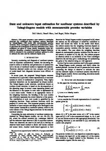
where A ∈ "n×n , B ∈ "n×m , E ∈ "n×r and C ∈ "p×n . The matrix E is referred to as the unknown input distribution matrix and is assumed to be a known full column rank matrix (with r ≤ p). The term Ed(t) can actually be used to describe additive disturbances as well as many kinds of modeling uncertainties such as noise, nonlinear or time-varying terms, linearization and model reduction errors, parameter variations, etc. It can also represent system inputs which are inaccessible (or unmeasurable) [10]. It is important to note that much work has been done on estimating the distribution matrix E when it is not fully known (see for example [11], [16], [17]). In all the literature available for this problem, the observer proposed fall in the class of Luenberger-like observers, namely: z(t) ˙ = F z(t) + Ly(t) + T Bu(t) x ˆ(t) = z(t) + Hy(t)
(3) (4)
where F ∈ "n×n , L ∈ "n×p , T ∈ "n×n and H ∈ "n×p . This observer can be represented by the structure in Fig. 1.
Fig. 1.
The structure of UIO.
As mentioned in section I, several approaches for designing a UIO (particularly, for designing F , L, T and H to guarantee observer stability) have been developed. In this section, we focus on the technique developed by Chen, Patton and Zhang in [7]. In their work, the necessary and sufficient existence conditions of UIO were presented. Compared with other UIO design methods, these conditions are easy to verify and the design procedure is relatively simple. Their results can be summarized as follows. By noting
(5) (6)
F = A − HCA − L1 C; L2 = F H
with F stable
L = L 1 + L2
(7) (8) (9)
then the observer in (3)-(4) has the stable undisturbed error dynamics e˙ = F e, they defined (3)-(4) as a UIO for the system (1)-(2) if it satisfies (5)-(9). Based on that definition, their main result was given by the following theorem: Theorem 1: [7] Necessary and sufficient conditions for (3)-(4) to be a UIO for the system (1)-(2) are: (i) rank (CE) = rank(E). (ii) (A"1 , C) is a detectable pair, ! −1 where A1 = A − E (CE)T CE (CE)T CA. They also presented a systematic design procedure to compute the matrices F , L, T and H that satisfy (5)-(9). In this paper, we study the nonlinear UIO design problem for the class of nonlinear Lipschitz systems of the form: x(t) ˙ = Ax(t) + Γ(y, u, t) + Φ(x, u, t) + Ed(t) y(t) = Cx(t)
(10) (11)
and where the function Φ(x, u, t) satisfies a uniform Lipschitz continuity globally in x, i.e, % Φ(x1 , u, t) − Φ(x2 , u, t) % ≤ α % x1 − x2 %
(12)
for all u ∈ "m and t ∈ " and for all x1 and x2 ∈ "n . Here α ∈ " is referred to as the Lipschitz constant and is independent of x, u and t. Lipschitz systems constitute a very important class. Notice that any system of the form x˙ = f (x, u) can be expressed in the form of (10) as long as f (x, u) is continuously differentiable with respect to x. Many nonlinearities satisfy (12) at least locally. Examples include trigonometric nonlinearities occurring in robotic applications, the nonlinearities which are square or cubic in nature, etc. Therefore, much research has been done on the observer design problem for Lipschitz systems without additive disturbances (see for example [18], [19]). However, in this paper we consider the case of nonzero additive disturbances, i.e, the Lipschitz unknown input observer (LUIO) design problem. Our approach is based on the extension of the UIO structure in (3)-(4) to a more general dynamic framework. We further tackle the LUIO design problem by showing that, using the new dynamic observer, this problem is equivalent to a standard H∞ control problem. The extra design freedom offered by the dynamic formulation is used to deal with the nonlinearities. The following definitions and notations will be used throughout the paper: Definition 1: (L2 Space) The space L2 consists of all + → "q having a Lebesque measurable functions u : "# $∞ ∆ finite L2 norm %u%L2 , where %u%L2 = % u(t) %2 dt, 0 with %u(t)% as the Euclidean norm of the vector u(t). For a system H : L2 → L2 , γ(H) will represent its L2 gain $Hu$ defined as: γ(H) = supu $u$LL2 . It is well known that,
4199
2
for a linear system H : L2 → L2 with a transfer matrix ˆ ˆ H(s), γ(H) is equivalent to the H∞ norm of H(s) defined ∆ ˆ ˆ as: γ(H) = % H(s) %∞ = supω∈& σmax (H(jω)), where ˆ The σmax represents the maximum singular value of H(ω). matrices In , 0n and 0nm are used to represent the identity matrix of order n, the zero square matrix of order n and the zero n by m matrix respectively. The symbol Tˆyu is used to represent the transfer matrix u to output & % from input A B (when used as y. The partitioned matrix K = C D an operator from y to u, i.e, u = Ky) represents the state space representation (ξ˙ = A ξ + B y, u = C ξ + D y).
Lemma 1: The error dynamics of (13)-(16) as an observer for (1)-(2) is asymptotically stable and decoupled from the disturbance term d(t) if the following conditions are satisfied:
%
III. A NEW UIO DYNAMIC DESIGN In this section, we first present a dynamic generalization of the UIO structure in (3)-(4) developing conditions that guarantee the observer stability in this case. We then extend the results in [7] to this new framework by proving that the same conditions of Theorem 1 are necessary and sufficient for the new UIO dynamic design. A. Dynamic generalization of the classical UIO structure Throughout this paper, we will make use of dynamical observers with the following structure: z(t) ˙ = w1 (t) + w2 (t) + T B u(t)
(13)
x ˆ(t) = z(t) + H y(t)
(14)
where w1 (t) and w2 (t) are obtained by applying dynamical compensators on the vectors z and y respectively. In other words, w1 and w2 are given from: ξ˙1 = AF ξ1 + BF z, w1 = CF ξ1 + DF z ξ˙2 = AL ξ2 + BL y, w2 = CL ξ2 + DL y
(15) (16)
This can be represented by the structure in Fig. 2.
Fig. 2.
AF CF
HCE = E
(17)
T = In − HC
(18)
BF DF
AF & BF stable; with CF DF
= = = =
AL BL1 C −CL A − HCA − DL1 C (19)
DL2 = DF H BL2 = − BF H
(20) (21)
BL = BL1 + BL2 (22) DL = DL1 + DL2 (23) In the next subsection, we show that same conditions of theorem 1 (which were necessary and sufficient to satisfy (5)-(9)) are still necessary and sufficient for (17)-(23). B. Dynamic UIO: definition and existence conditions We start by introducing the following definition: Definition 2: (Dynamic UIO) An observer of the form (13)-(16) is referred to as a dynamic UIO for the system (1)-(2) if it satisfies conditions (17)-(23). This definition accommodates the observer defined in [7] as a special case and we here prove that the same conditions of theorem 1 hold for this more general definition as follows: Theorem 2: There exists a dynamic UIO for the system (1)-(2) (according to Definition 2) if and only if : (i) rank (CE) = rank (E) (24) (ii) (A1 , C) is a detectable pair, where (25) ! "−1 (CE)T CA. A1 = A − E (CE)T CE Proof : The proof is constructive (shows the steps needed to design a dynamic UIO). It is a direct result of the proof of theorem 1 and of the interpretation of conditions (19)-(23) as follows. It was proved in [10] that (17) is solvable iff (24) is satisfied and that the general solution is: ! " (26) H = E(CE)+ + H0 Ip − CE(CE)+
where H0 is an arbitrary n by p matrix and (CE)+ is the left inverse of (CE) which is: ! "−1 (CE)T (CE)+ = (CE)T CE
Dynamic structure of UIO.
Compared with the one in Fig. 1, this new structure offers more dynamics which will be used in section IV to tackle the LUIO design problem. Towards that goal, we consider first its use as a UIO for the system (1)-(2). The following lemma develops conditions for observer stability in this case (see proof in Appendix I).
The rest of the proof follows by noting that satisfying (19) is equivalent to finding AL , CL , & BL1 and DL1 % AL BL1 C such that is stable. This −CL A − HCA − DL1 C is equivalent to the stabilization problem in Fig. 3 which is solvable iff (A − HCA, C) is detectable. Finally, notice that for any H that satisfies (26), (A − HCA, C) is detectable iff (A1 , C) is detectable (as proven in [10]) where A1 is given by (25). Therefore,
4200
and where K is the dynamic controller & % AL BL1 K= CL DL1
Plant “G” "
A − HCA −In C 0pn Controller “K” AL CL Fig. 3.
BL1 ! DL1
Stabilization problem.
conditions (i) and (ii) are necessary and sufficient to satisfy (17)-(23) and the proof is complete. ' As a conclusion, with the same existence conditions of the UIO in [7], the dynamic UIO design is reduced to the stabilization problem in Fig. 3 which has a set of controllers [20] as its solution. We will make use of this extra design freedom in section IV when dealing with the Lipschitz case.
This can also be represented by Fig. 4 where the plant G has the state space representation in (35) with the matrices in (31)-(32) and where the controller K is given from (34). B2 A B1 (35) gˆ(s) = C1 D11 D12 C2 D21 D22 ω " ν"
Fig. 4.
For the Lipschitz unknown input observer (LUIO) design problem, we first prove that solving an H∞ problem is necessary and sufficient for observer stability. We then show that this problem is equivalent to a standard H∞ problem. Finally, we present a systematic design procedure for the LUIO within the H∞ framework. A. An H∞ formulation of the LUIO design problem For a Lipschitz system of the form (10)-(11) and where Φ(x, u, t) satisfies (12) with a Lipschitz constant α, we consider the use of the following observer: z(t) ˙ = w1 (t) + w2 (t) + T Γ(y, u, t) + T Φ(ˆ x, u, t) (27) x ˆ(t) = z(t) + Hy(t) (28) where w1 (t) and w2 (t) are obtained from (15) and (16) respectively and where the parameters of the observer satisfy the conditions (17)-(23). Similar to the linear case (see proof of lemma 1 in Appendix I), it can be seen that the error dynamics of this observer is given from: ξ˙ = AF ξ + BF e e˙ = CF ξ + DF e + T (Φ(x, u, t) − Φ(ˆ x, u, t))
(29) (30)
ω = φ˜ = Φ(x, u, t) − Φ(ˆ x, u, t) ν = K (y − yˆ) ζ = e=x−x ˆ ϕ = y − yˆ
ϕ
Standard setup.
The following theorem is the main result of this section: Theorem 3: Given the Lipschitz system of equations (10)-(11), the state x ˆ of the observer (27)-(28) (satisfying conditions (17)-(23)) globally asymptotically converges to the system state x for all Φ satisfying (12) with Lipschitz constant α if and only if K in (34) satisfies / 0 1 (36) supω∈& σmax Tˆζω (jω) < α Proof : (Sufficiency) Using the variable definitions in (33) and the matrices in (31), (32) and (34), Tˆζω can be represented as follows: T A − HCA − DL1 C −CL BL1 C AL 0n Tˆζω = Tˆeφ˜ = In 0n 0n (37) and is such that γ(Tˆeφ˜) =% Tˆeφ˜ %∞ < α1 according to (36). The proof of sufficiency follows by noting that the estimation error e is given from the feedback interconnection of Tˆeφ˜ and ∆ as shown in Fig. 5 where ∆ is the static nonlinear time-varying operator defined as follows: ∆(t) : e → φ˜ = Φ(x, u, t) − Φ(ˆ x, u, t) = Φ(e + x ˆ(t), u(t), t) − Φ(ˆ x(t), u(t), t)
which (by using (19)) can also be represented by the transfer function Tˆζω in the following so-called standard form: % & " ω ! " ! ˙ ψ = A − HCA ψ + T −In (31) ν % & % & % & % & 0 0n ω ζ I (32) = n ψ+ n C 0pn 0pn ν ϕ where
ζ "
G
K !
IV. D ESIGN OF L IPSCHITZ UNKNOWN INPUT OBSERVERS
(34)
φ˜
"
∆ Fig. 5.
(33)
e
Tˆeφ˜
!
Feedback interconnection.
1 In this loop, γ(Tˆeφ˜) < α as mentioned earlier and, although an exact expression for ∆ is not available, we
4201
have γ(∆) ≤ α because from (12) it follows that #$ ∞ 2 α %x−x ˆ %2 dt 0 γ(∆) ≤ #$ ≤ α ∞ 2 dt % x − x ˆ % 0
Using the bounds on the L2 gains of the Tˆeφ˜ and ∆, we will make use of a dissipativity argument by noting that the following properties are satisfied for the feedback interconnection of Fig. 5: (i) ∆ is a static nonlinearity (no internal states) and Tˆeφ˜ is given from (37). (ii) The mappings Tˆeφ˜ : φ˜ → e and ∆ : e → φ˜ have finite L2 gains γ(Tˆeφ˜) and γ(∆), and moreover they satisfy γ(Tˆeφ˜).γ(∆) < 1. (iii) Tˆeφ˜ and ∆ are dissipative with respect to the supply rates ω1 = −eT e + γ(Tˆeφ˜)2 φ˜T φ˜ and ω2 = −φ˜T φ˜ + α2 eT e respectively. We will denote by S1 and S2 the storage functions associated with these supply rates. It is an straightforward application of Corollary 1 in reference [21] that S1 + aS2 , a > 0, is a Lyapunov function for the feedback system of Fig. 5, and that, since γ(Tˆeφ˜)γ(∆) < 1, the composite system is asymptotically stable. This implies that e → 0 as t → ∞. (Necessity) This is a direct result of the small gain theorem for LTI systems (see the proof of Theorem 4 in [19] for more details) which implies that if γ(Tˆeφ˜) ≥ α1 in Fig. 5, ˆ (s) %∞ ≤ α then there exists Φ(x, u, t) = M (t)x with % M such that the closed loop system in Fig. 5 is unstable. ' B. Problem regularization
Despite the result in theorem 3, observer synthesis can not be carried out directly using the standard H∞ solution since the standard form in (31)-(32) does not satisfy all of the regularity assumptions in the H∞ framework [20]. However, by considering a “weighted” disturbance term in the output, i.e using (38) instead of (11): y(t) = Cx(t) + , η(t), ,>0 (38) then the standard form in (31)-(32) has now the form: % & ω " " ! " !! ψ˙ = A − HCA ψ + T 0np −In η(t) ν " ! 0n 0np ζ In = ψ + ! " C 0pn ,Ip ϕ
(39) & ω 0n η(t) (40) 0pn ν
%
This can also be represented by the setup in Fig. 4, except for redefining the matrices of gˆ(s) in (35) and replacing "T ∆ ! ω by ω ¯ which is defined as: ω ¯ = ω η(t) . This standard form, however, still does not satisfy the regularity T D12 is singular. assumptions in the H∞ problem since D12 Fortunately, regularization can be done by simply extending the external output ζ to include the “weighted” vector βν, β > 0. This adds another change in Fig. 4 consisting of
"T ∆ ! replacing ζ by ζ¯ defined as: ζ¯ = ζ βν . The entries of gˆ(s) in (35) are then given by the following state space realization (where A¯ = A − HCA) % & ω " " ! " !! (41) ψ˙ = A¯ ψ + T 0np −In η(t) ν & % & % % & % & % & 0n 0n 0np ζ In ω βν 0n βIn = ψ + 0n 0np η(t) ! " 0pn ,Ip ϕ C ν 0pn (42)
It is now straightforward to see that all of the regularity assumptions summarized below [20] are now satisfied: ¯ 1) (A,B2 ) stabilizable: satisfied for any matrix A. ¯ (C2 ,A) detectable: satisfied iff (A,C) is detectable. T = ,2 Ip×p which is nonsingular. 2) D21 D21 T is nonsingular. D12 D%12 = β 2 In×n which & A − jωI B2 3) rank = 2n = full column rank. D12 & % C1 A − jωI B1 = n + p = full row rank. rank C2 D21 4) D22 = 0. It follows that all the regularity assumptions are satisfied iff (A−HCA, C) is detectable (with no new design restrictions over the design conditions of theorem 2). We also prove that this regular H∞ problem is actually equivalent to the original one introduced by theorem 3 in the following sense: Let T1 be the setup in Fig. 4 associated with (31)-(32), T2 the one associated with (39)-(40) and T3 the one associated with (41)-(42). And let Tˆ1 , Tˆ2 and Tˆ3 be their corresponding transfer matrices. The following two lemmas demonstrate a certain equivalence between these setups (the proof is omitted and is included in [22]). Lemma 2: Consider a stabilizing controller K for T1 and T2 , then % Tˆ1 %∞ < γ iff ∃ , > 0 such that % Tˆ2 %∞ < γ. Lemma 3: Given , > 0 and a stabilizing controller K for T2 and T3 , then % Tˆ2 %∞ < γ iff ∃ β > 0 s.t % Tˆ3 %∞ < γ. The previous results can be used to extend the results in theorem 3 showing that the observer gain K needed to stabilize the estimation error must solve a regular H∞ optimal control problem. To this end, we define the regular continuous H∞ control problem “Problem 1” as follows: Problem 1 Given , > 0 and β > 0, find S, the set of admissible controllers K satisfying % Tˆζ¯ω¯ %∞ < γ for the standard setup in Fig. 4 with G having the state space representation (35) along with the matrices in (41)-(42). Now we extend the result of theorem 3 as follows: Theorem 4: Given the Lipschitz system of equations (10)-(11), the state x ˆ of the observer (27)-(28) (satisfying the conditions (17)-(23)) globally asymptotically converges to the system state x for all Φ satisfying (12) with a Lipschitz constant α if and only if ∃ ,, β > 0 such that K (the controller in (34)) ∈ S ∗ (the set of controllers solving “Problem 1” defined above with γ = α1 ). Proof : A direct result of Theorem 3, Lemmas 2 and 3. '
4202
C. A LUIO design procedure The following iterative “binary search” procedure is then proposed to design the LUIO (27)-(28) for the system (10)-(11) satisfying the conditions (12), (24) and (25). Design procedure Step 1 Calculate H = E(CE)+ + H0 [Ip − CE(CE)+ ]; where H0 is an arbitrary n by p matrix and where which is given from (CE)+ is !the left inverse "−1 of CE (CE)T . (CE)+ = (CE)T CE Step 2 Set T = In − HC. Step 3 Set ,, β > 0 and γ ← α1 . Step 4 Test solvability of “Problem 1” (the H∞ problem defined in sec IV-B). If test fails, go to Step 6; otherwise solve the problem (using available software packages) and any K ∈ S is candidate for (34). Step 5 Calculate all the remaining gains of the LUIO using (19)-(23) and go to Step 7 . Step 6 Set , = 2% and β = β2 . If , or β < a threshold, then go to step 7 (a LUIO does not exist); otherwise go to Step 4. Step 7 Stop. Comments: • When the H∞ problem is not solvable, one can increase γ by decreasing the Lipschitz constant α. The statement in italic in step 6 can then be replaced by: decrease α and go to Step 3. With this change, the algorithm is guaranteed to work as α → 0. • Same design can be used when the output is disturbed as in (38). The small gain theorem guarantees that the estimation error e(t) ∈ L2 if η(t) ∈ L2 . V. C ONCLUSION
In this paper we considered the design of unknown input observers (UIO) for nonlinear Lipschitz systems. A new H∞ approach is proposed and is shown to be feasible with the same existence conditions of the linear UIO design. Our approach makes use of dynamical observers, an approach that shows promise given the additional degrees of freedom available to the designer. The introduced design procedure addresses the nonlinearity and the disturbance decoupling problems in the same framework and can be carried out using commercially available software, such as MATLAB. A PPENDIX I Proof of Lemma 1 Using (13)-(16) as an observer for the system (1)-(2) and defining the error ez = T x − z and the state ξ = ξ2 − ξ1 we have (with the help of (17)-(19)): e˙z = T (Ax + Bu + Ed) − w1 − w2 − T Bu = − CF ξ1 − CL ξ2 − [DF (T x − ez ) − T Ax + DL Cx] = CF ξ + DF ez − (DF T − T A + DL C) x
But from (18)-(20) and (23): T A − DF T = DL C. Then, e˙z = CF ξ + DF ez . Also, for the state ξ, we have: ξ˙ = AL ξ2 + BL y − AF ξ1 − BF z
= AL ξ2 + BL Cx − AF ξ1 − BF (T x − ez ) = AF ξ + BF ez − (BF T − BL C)x
But from (18), (19), (21) and (22): BF T = BL C. Then, ξ˙ = AF ξ +BF ez . Therefore, the observer error dynamics is (ξ˙ = AF ξ +BF ez , e˙z = CF ξ +DF ez ). From the stability of the matrix in (19), it follows that the error dynamics is asymptotically stable and decoupled from d(t), and the proof is completed by noting that e = x − x ˆ = x − (z + ' Hy) = (I − HC)x − z = ez . R EFERENCES [1] D. G. Luenberger, “An introduction to observers,” IEEE transactions on Automatic Control , vol. 16, pp. 596-602, 1971. [2] S. H. Wang, E. J. Davison, P. Dorato, “Observing the states of systems with unmeasurable disturbances,” IEEE transactions on Automatic Control , vol. 20, pp. 716-717, 1975. [3] S. P. Bhattacharyya, “Observer design for linear systems with unknown inputs,” IEEE transactions on Automatic Control , vol. 23, pp. 483-484, 1978. [4] N. Kbayashi, R. Nakamizo, “An observer design for linear systems with unknown inputs,” International Journal of Control , vol. 35, pp. 605-619, 1982. [5] F. W. Fairman, S. S. Mahil, L. Luk, “Disturbance decoupled observer design via singular value decomposition,” IEEE transactions on Automatic Control , vol. 29, No.1, pp. 84-86, 1984. [6] M. Hou, P. C. M¨uller, “Design of observers for linear systems with unknown inputs,” IEEE transactions on Automatic Control , vol. 37, No.6, pp. 871-875, 1992. [7] J. Chen, R. J. Patton, H. Zhang, “Design of unknown input observers and robust fault detection filters,” International Journal of Control , vol. 63, No.1, pp. 85-105, 1996. [8] K. Watanabe, D. M. Himmelblau, “Instrument Fault Detection in Systems with Uncertainty”, Int. J. Sys. Sci, Vol 13, pp. 137-158, 1982. [9] J. W¨unnenberg, P. M. Frank, “Sensor Fault Using Detection via Robust Observer”, System Fault Diagnosis, Reliability& Related Knowledge-Based Approaches, S.G. Tzafestas, M. G. Singh and G. Schmidt (eds), Reidel Press, Dordrecht, pp. 147-160, 1987. [10] J. Chen, R. J. Patton, “Robust model-based fault diagnosis for dynamic systems”, Kluwer Academic Publishers, 1999. [11] R. J. Patton, J. Chen, “Optimal selection of unknown input distribution matrix in the design of robust observers for fault diagnosis”, Automatica, vol. 29, No. 4, pp 837-841, 1991. [12] J. W¨unnenberg, “Observer-based fault detection in dynamic systems”, PhD thesis, University of Duisburg, Germany, 1990. [13] P. M. Frank, R. Seliger, “Fault detection and isolation in automatic processes”, in C. Leondes (ed.), Control and dynamic systems, vol. 49, Academic press, pp 241-287, 1991. [14] R. Seliger, P. M. Frank, “Fault diagnosis by disturbance decoupled nonlinear observers”, Proceedings of the 30th IEEE conference on decision and control, Brighton, UK, pp 2248-2255, 1991. [15] R. Seliger, P. M. Frank, “Robust residual evaluation by thersohld selction and a performance index for nonlinear observer-based fault diagnosis”, Proceedings of the International conference on fault diagnosis: TOOLDIAG’93, Toulouse, pp 496-504, 1993. [16] J. Gertler, M. K. Kunwer, “Optimal residual decoupling for robust fault diagnosis”, International Journal of Control, vol. 61, No. 2, pp 395-421, 1995. [17] A. Edelmayer, J. Bokor, F. Szigeti, L. Keviczky, “Robust detection filter design in the presence of time-varying system perturbations”, Automatica, vol. 33, No. 3, pp 471-475, 1997. [18] S. Raghavan, J. K. Hedrick, “Observer design for a class of nonlinear systems,” International Journal of Control, Vol. 59, No. 2, pp. 515528, 1994. [19] R. Rajamani, “Observers for Lipschitz nonlinear systems,” IEEE transactions on Automatic Control, vol. 43, No. 3, pp. 397-401, March 1998. [20] K. Zhou, J. C. Doyle, “Essentials of robust control”, Prentice-Hall, NY, 1998. [21] D. J. Hill and P. J. Moylan, “Stability Results for Nonlinear Feedback Systems,” Automatica, Vol. 13, pp. 377–382, July 1977. [22] A. M. Pertew, H. J. Marquez and Q. Zhao, “H∞ synthesis of unknown input observers for nonlinear Lipschitz systems,” submitted to the International Journal of Control, 2004.
4203