Abstract-Antiresonant reflecting optical waveguide. (ARROW)-type diode lasers have been optimized for high-power, single-spatial-mode operation. Calculated ...
5; 1' IEEE PHOTONICS TECHNOLOGY LETTERS, VOL. 4, NO. 11, NOVEMBER 1992
1204
Design Optimization of ARROW-Type Diode Lasers L. J. Mawst, D. Botez, C . Zmudzinski, and C. Tu Abstract-Antiresonant reflecting optical waveguide (ARROW)-typediode lasers have been optimized for high-power, single-spatial-mode operation. Calculated modal behavior predicts strong intermodal discrimination with low loss for the fundamental ARROW mode. Single-lobe far-field operation is obtained only when the high-index reflecting (antiresonant) cladding layers correspond to an optical thickness of A , ( m + .3 / 4) where A , is the lateral (projected) wavelength of the leaky wave in the high-index layers, and m in an integer (rn = 0,1, * ). Experimental results include stable, single-spatial mode operation to 500 mW peak pulsed power and 300 mW CW power at an emission wavelength of 0.98 pm.
--
H
IGH-output-power, stabilized single-mode diode lasers are needed for many applications such as sources for frequency doubling, end pumping of solid-state lasers, and rare-earth-doped fiber amplifiers. Conventional ridge waveguide diode lasers exhibit stable singlemode operation to 180-210 mW output power with a spot size of 2-3 p m [l], [2]. Beyond those power levels, the beams become unstable or exhibit multimode operation [2]. Furthermore, their small spot size limits the reliable output power level to approximately 100 mW. Much higher reliable single-mode power levels ( - 0.5 W) have been obtained from phase-locked arrays of antiguides because of their large (80-120 pm) emitting aperture [3]. However, the output from such large apertures, even though coherent, is difficult to couple to single-mode fibers. Recently, the antiresonant reflecting optical waveguide (ARROW) passive-guide structure [4]-[6] was used to stabilize the lateral mode of an antiguided diode laser [7]. The ARROW laser is well suited to fiber coupling applications because it exhibits stable single-spatial-mode operation to high power levels with a spot size which closely matches the fiber spot width (4-6 pm). These features are a direct result of the large built-in (negative) indexsteps ( A n > 0.03) and strong discrimination against higher-order spatial modes. We present here optimization guidelines for ARROW-type laser structures with emphasis on obtaining low-optical-loss, mode-stabilized devices. Using such guidelines, record single-mode power levels have been achieved from ARROW lasers incorporating strained-layer InGaAs quantum-well active layers ( A = 0.98 pm). Manuscript received July 13, 1992; revised August 28, 1992. The authors are with TRW Space & Technology Group, Redondo Beach, CA 90278. IEEE Log Number 9204330.
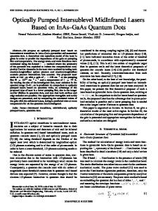
Lateral ARROW-type structures have been demonstrated using a self-aligned stripe [SI (SAS) diode laser geometry. Previous ARROW structures incorporated a GaAs quantum well active region with an emission wavelength of 0.85 pm. A similar structure, incorporating a strained In,Ga,_,As quantum well active layer, is used here to obtain emission wavelengths of 0.97-1.03 pm, making them suitable as pump sources for rare-earthdoped fiber amplifiers. The SAS structure is fabricated by two-step MOCVD as described previously [9]. A thin (0.05 pm) Al,Ga, -,As (x = 0.6) current blocking layer is used to restrict current injection to the low-index core region. A desirable feature of the SAS geometry (compared to ridge-guide structures) is that it is a buried-type structure with a planar top configuration for efficient heat sinking. A high-index passive waveguide in close proximity to the active region results in a built-in lateral (effective) index variation corresponding to the ARROW structure, as described previously [7]. The relatively large index variation ( A n = 0.03 - 0.2) makes the device insensitive to carrier- or thermally induced refractive-index variations. For device optimization, the magnitude of the lateral index step can be simply adjusted by varing the composition (x) of the Al,Ga,.,As passive guide layer during the first phase growth. The ARROW structure consists of a low-index core region, which defines the spot size of the device, surrounded by highly reflecting cladding layers. The lateral index profile for an ARROW laser with a 4 p m core width is shown in Fig. 1. Our analysis is limited to devices of 4 p m core widths, although core widths as large as 6 p m provide single-mode behavior as well. The reflecting cladding layers are designed in thickness and refractive index to correspond to an odd number of quarter lateral wavelengths (i.e., antiresonant) of the radiation leakage from the fundamental ARROW mode. This results in low loss for the antiresonant fundamental ARROW mode, while higher-order ARROW modes have much higher edge losses 141. The modal behavior of the ARROW structure is modeled using an effective index approximation with exact solutions being calculated for the lateral index variation as shown in Fig. 1. The calculated modal edge radiation loss for the fundamental and first-order ARROW modes are shown in Fig. 2 as a function of lateral index step ( A n ) between the ARROW core region and the high-index reflecting layers of thickness S corresponding to an optical path length of (3/4)A, where A, is the lateral wavelength in the high-
1041-1135/92$03.00
1T
-~
~~
0 1992 IEEE
1205
MAWST et al.: ARROW-TYPE DIODE LASERS
An = 0.03 = n 1 - n o
An = 0 005
g Index
10
3
2 2
4
59 0 0
4
Fig. 1. Lateral index profile for single-core ARROW laser structure. A, and A, are the lateral wavelength of the radiation leakaee in the low-index and high-index regions, iespectively.
-
05
U
-100-60 2 0 2 0 6 0 1 0 0 X (pm)
ii - 0 5 -100-60 2 0 2 0 6 0 1 0 0 X (Km)
0'51
0 . 5 ~
0.4
03
/~IRST-ORDER MODE
5 0.2
I
U
0.1
01 00
-600 -200 0 2 0 0 600 ANGLE (DEGREES)
I I I I
FUNDAMENTAL
I ~ O D E 020
030
\ 040
-
Anx10
ANTIRESONANCE
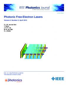
Fig. 2. Calculated edge radiation losses for the first-order and fundamental ARROW modes as a function of lateral index step (An). A low loss fundamental ARROW mode is obtained in a large range around the antiresonant point, with large loss for the first-order mode.
index layers and is given by
[lo]
A, = 29~14-
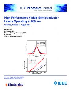
where is the mode propagation constant, n , is the index in the high-index layers, and k , is the free space propagation constant 27~/A (in this case A = 0.85p.m). Note that the fundamental ARROW mode exhibits low loss over a relatively large range in A n , while the first-order mode suffers large loss. This fact ensures single-mode operation to high output power levels. For maximum intermodal discrimination it would seem tempting to build a structure of much lower An than the antiresonant case, but that in turn causes less power in the central-lobe of the far-field radiation pattern because of an increase in side-lobe intensity. The calculated optical field distribution for the fundamental ARROW mode near the antiresonant point is shown in Fig. 3. The fundamental ARROW mode has large field intensity in the low-index core region corresponding to a half the lateral wavelength [lo] (A,) in the low index region. Lower field intensity occurs in the surrounding high-index and low-index reflecting layers corresponding to 3h1/4 and A,/4 lateral wavelengths, respectively. This field distribution results in a nearly single-lobe far-field radiation pattern with 70-80% of the energy on-axis (see Fig. 3). It has been previously shown
11
-2000 200 600 ANGLE (DEGREES)
Fig. 3. Calculated optical field intensities for fundamental ARROW modes corresponding to structures where the optical path length of the high-index reflecting cladding layers equals a) 3 4 / 4 lateral waves; and b) A,/4 lateral waves. Single-lobe far-field emission is obtained in the 3AI/4 wave structures.
I
010
800
[7] that much as 90% of the beam energy can be contained in the central lobe of the far-field pattern by optimizing both the width and the refractive index of the reflecting high-index layers. The edge loss (modal discrimination) characteristics of the ARROW modes are similar for structures with any odd integral number of quarter lateral wavelengths in the high-index cladding layers. However, for diode lasers (in contrast with previous passive ARROW structures [4]-[61 an additional constraint is placed on the design because it is desirable to have a single-lobed far-field radiation pattern. This occurs when the field in the outer low-index cladding layers is in-phase with the field in the core region. Then for single-lobe operation it is required that the reflecting high-index cladding regions correspond to an optical thickness A,(m 3/4) (where m = 0,1,2 ...1. Double-lobed operation is obtained for structures with (4m + 1) A,/4 ( m = 0,1,2 ) in the high-index reflecting layers because the field in the low-index outer cladding layers is out-of-phase with that in the core region. For example, the double-lobed far-field pattern shown in Fig. 3 occurs when the high-index reflecting layers have an optical path length of approximately A,/4. Similar behavior occurs when the optical path length is 5A,/4. For these reasons, we have designed the ARROW lasers reported here to operate with 3Al/4 within the high-index reflecting layers. Further optimization should be possible by using a larger index-step structure ( A n = 0.18) where the high-index reflecting layers correspond to 7A, /4. Calculations indicate that such a device has a larger fraction of field intensity in the central core region and exhibits a single-lobed beam pattern. In addition, it is expected to have increased stability due to the large lateral index-step and strong discrimination against the first-order ARROW mode ( a 1= 90 cm-').
+
I
I IEEE PHOTONICS TECHNOLOGY L E m R S , VOL. 4, NO. 11, NOVEMBER 1992
1206
/)
ARROW - PULSED OPERATION 500[
b=097pm
L=1000pm
-.
HWAR
I / -
4001
t “
I
/
-24”
-24’
0
0
-24O
-24”
-
M 0 -24”
-24”
‘0
4oa
Boo 1200 1600 zoo0 2400 INJECTION CURRENT (mA)
above which multilongitudinal operation is observed. Threshold currents are as low as 30-40 mA with external differential quantum efficiencies of 30-40%. Differential quantum efficiencies as high as 70% have been obtained previously [7] in ARROW structures with GaAs quantum wells, primarily due to the higher efficiency of the particular laser base material. Similar performance (7= 70%) can be expected by using optimized InGaAs active layer material. Recently, large core-width (6 pm) ARROW lasers have been fabricated [111. Single-mode output powers of 300 mW CW have been obtained. The use of nonabsorbing mirrors (NAM) technology together with the large (6 pm) aperture ARROW structure should 300 mW. allow reliable operation at power levels of In conclusion, ARROW-type diode lasers have been optimized in terms of intermodal discrimination and farfield beam profile. Antiresonant operation results in lowloss fundamental ARROW mode oscillation over a large operating range. Single-lobe far-field beam profiles are obtained when the high-index (reflecting) cladding layers have an optical path length of A, (rn 3/41. Record-high single-mode powers have been achieved and thus strained In,Ga,-,As active layer ARROW devices appear as promising candidates for high-power single-mode sources for pumping rare-earth-doped fiber amplifiers.
2800 3200
Fig. 4. Power-current characteristics and lateral far-field patterns under pulsed operation for a 4 p m wide-core structure with an emission wavelength of 0.97 pm.
+
SAS-type ARROW lasers were fabricated with InGaAs REFERENCES
(x = 0.20) double-quantum-well active regions, resulting in an emission wavelength of 0.97-0.98 pm. The composition ( x ) of the Al,Ga,-,As passive guide layer was adjusted to a value of x = 10-13% corresponding to a lateral index step (An) of 0.04-0.05. Devices with 1 mm cavity lengths were HR/AR coated and mounted junction down on copper heatsinks. Stable, fundamental ARROW mode operation is observed as high as 500 mW output power under pulsed operation as shown in Fig. 4. The far-field lobe halfwidth is measured to be 9.0”, which agrees well with a calculated value of 8.6”. However, typically above 300 mW output power, the “shoulders” of the central lobe in the far-field pattern begin to increase in intensity. Examination of the near-field indicates that above 300 mW the field intensity in the outer low-index cladding layers begins to increase. The cause of this effect is not yet understood, but could be related to a breakdown of current confinement to the core region. CW operation has been achieved up to 300 mW and similar behavior to pulsed operation is observed. The far-field data indicate that the first-order ARROW mode, which has far-field lobes at _+5”and k 15”, is effectively suppressed throughout the operating range. These data represent the highest stable single-spatial-mode powers, from single-stripe laser diodes reported to date. The spectral characteristics were measured to be single longitudinal mode (under CW conditions) from just above laser threshold to typically 150-175 mW output power,
1T
B. Elman, W. F. Shariin, F. D. Crawford, W. C. Rideout, J. Lacourse, and R. B. Lauer, “High power 980 nm ridge waveguide lasers with etch-stop layer,” Electron. Lett., vol. 27, pp. 2032-2033, 1991.
J. S. Major, W. Gignac, D. F. Welch, and D. Scifres, “Pump lasers for erbium-doped fibers,” in Roc. CLEO ’92, Anaheim, CA, 1992, pp. 190-197. L. J. Mawst, D. Botez, M. Jansen, T. J. Roth, C. Tu, and C. Zmudzinski, “0.5 W CW Diffraction-limited-beam operation from high-efficiency resonant-optical waveguide diode-laser arrays,” Electron. Lett., vol. 25, no. 5, pp. 1586-1587, 1991. M. A. Duguay, Y. Kokubun, T. L. Koch, and L. Pfeiffer, “Antiresonant reflecting optical waveguides in Si0,-Si multilayer structures,” Appl. Phys. Lett., vol. 49, no. 1, pp. 13-15, 1986. T. L. Koch, U. Koren, G. D. Boyd, P. J. Corvini, M. A. Duguay, “Antiresonant reflecting optical waveguides for 111-V integrated optics,” Electron. Lett., vol. 23, no. 5, pp. 244-245, 1987. T. Baba, Y. Kokubun, T. Sakaki, and K. Iga, “Loss reduction of an ARROW waveguide in shorter wavelength and its stack configuration,” J. Lightwaoe Technol., vol. 6, pp. 1440-1445, 1988. L. J. Mawst, D. Botez, C. Zmudzinski, and C. Tu, “Antiresonantreflecting-optical-waveguide-type,single-mode diode lasers,” Appl. Phys. Lett., Aug. 3, 1992. J. J. Coleman and P. D. Dapkus, “Single-longitudinal-modemetalorganic chemical-vapor-depositionself-aligned GaAlAs-GaAs double-heterostructure lasers,” Appl. Phys. Left., vol. 37, pp. 262-263, Aug. 1980. L. J. Mawst, D. Botez, C. Zmudzinski, M. Jansen, C. Tu, T. J. Roth, and J. Yun, “Resonant Self-aligned-stripe antiguided diode laser array,” Appl. Phys. Lett., vol. 60, pp. 668-670, 1992. D. Botez, L. J. Mawst, G. Peterson, and T. J. Roth, “Phase-locked arrays of antiguides: Modal content and discrimination,” IEEE J. Quantum Electron., vol. 26, pp. 482-495, 1990. L. J. Mawst, D. Botez, C. Zmudzinski, and C. Tu, “0.3 W CW single-spatial-modeoperation from large-core ARROW-type diode lasers,” Electron. Lett., vol. 19, Sept. 10, 1992.