942
Computer-Aided Design and Applications © 2008 CAD Solutions, LLC http://www.cadanda.com
Design Process Knowledge Reuse Challenges and Issues David Baxter1, James Gao2 and Rajkumar Roy1 1
Cranfield University,
[email protected],
[email protected] 2 Greenwich University,
[email protected] ABSTRACT
Product knowledge support needs are compared in two companies with different production volumes and product complexity. Knowledge support requirements identified include: function, performance data, requirements data, common parts, regulatory guidelines and layout data. A process based data driven knowledge reuse method is evaluated in light of the identified product knowledge needs. The evaluation takes place through developing a pilot case with each company. It is found that the method provides more benefit to the high complexity design domain, in which a significant amount of work takes place at the conceptual design stages, relying on a conceptual product representation. There is not such a clear value proposition in a design environment whose main challenge is layout design and the application of standard parts and features. The method supports the requirement for conceptual product representation but does not fully support a standard parts library. Keywords: design knowledge reuse, design process support, product knowledge analysis. DOI: 10.3722/cadaps.2008.942-952 1. INTRODUCTION The need for design knowledge reuse in product development is driven by the design challenge: to produce the right product in the minimum amount of time with minimum costs. There have been several methods proposed to support design reuse [1]. Lang et al suggest that hard copy notebooks remain the most commonly used method to record design knowledge, with the obvious limitation of sharing that knowledge. By capturing and storing design intent, rationale, and history in a computer based system, design knowledge can be shared and reused. [2]. Design knowledge reuse methods must consider a broad functional context. Dani and Harding suggest that technical solutions to reuse problems are not adequate, and that factors affecting reuse are interdependent and should be addressed simultaneously [3]. They implement a value net approach to the reuse process, which takes account of multiple viewpoints and helps the organization to identify appropriate reuse activities through interaction with a reuse agent and a knowledge base. Bohm and Stone investigated manual design methods to identify requirements for computer support. Categorizing design knowledge into supporting functions that describe manufacturing, assembly or support features allows for a greater level of detail in the design repository. They developed a system to display the support functions alongside components [4]. Design reuse, then, must account for knowledge that supports the overall design context, not just the knowledge that resides in a design artefact. Design process support is an integral element of effective design reuse [5]. Several methods have been proposed to support the design process, including business process modeling [6], workflow based methods [7] [8], and design process coordination support [9]. A potential extension to knowledge reuse through process support is the definition of the engineering process tasks and data support requirements. This paper seeks to investigate the potential for applying a process based data driven design knowledge reuse method [10] in a high volume moderate complexity design scenario. The method was proposed to address the needs of a medium volume high complexity design scenario. The Computer-Aided Design & Applications, 5(6), 2008, 942-952
943
knowledge support requirements are investigated in each case, then assessed against the features of the method. The method is evaluated through company case studies. 2. PRELIMINARY INVESTIGATION A preliminary investigation took place with three companies, in order to investigate the issues with design knowledge reuse in practice. The investigation sought to identify and classify the organization structure, product type and complexity, design tools and methods, product development strategy, manufacturing, and the current methods and extent of design reuse. A summary of the findings are presented in table 1.
Organisation structure
Company 1 Project based
Design complexity Design technology Design process detail Knowledge management maturity Specification source Product family
Medium Medium Medium Medium
Regulation Production volume Production investment Relative customer power Development time
Medium Medium Medium High 3 years
Application driven Wide range of variants
Company 2 Project based (customer) Low Low / medium Low Low
Company 3 Product based (modules) Very high High High High
Application driven Small number of variants High High Low Very high 2 years
Application driven Small number of variants Very high Low Very high High 3 years
Tab. 1: Summary of findings from the initial investigation. The preliminary investigation showed that design reuse is lacking, and that there are several limitations to design knowledge reuse in practice. There was not a clear design reuse strategy in any of the organisations. Design reuse practices that were in use were not part of a wider coherent structure, and this limited the potential to share good practice. The main source of design knowledge reuse was designer personal notebooks, shared documents and the company intranet. Each one has problems associated: personal notebooks are not shared, so can only be reused by the original author. Intranet use presented a similar challenge, largely due to the user driven content: whilst the notes are available, they are not easy to find, and they are not presented in a way that makes them easy to reuse. Shared documents provided a level of design reuse in one company; however the value of the document seemed to diminish as its size increased. The larger the document grows, the less often it is used. These knowledge reuse methods, where they are available for reuse by other designers, lack context. In the product development processes, there was a clear engineering bias. Whilst there is a business process structure in place in each case, the focus of the design team is on the achievement of the engineering goals. Since engineering goals can be met better with a new solution (rather than an existing solution), this tends to be what happens. The engineering focused applied practice was not in line with the commercially focused prescribed practice. There is a need to reconcile the engineering and business objectives in a single coherent design method that includes design knowledge reuse as an integral element. In summary, the challenges to design knowledge reuse in practice are: Access to relevant and contextualised captured design knowledge. Storage methods do not support reuse in context: centralised and unstructured vs. locally held and unavailable. Developing a relationship between design reuse and the product development process. Integrating engineering and business objectives. The proposed design knowledge reuse method described in the following section takes these industrial challenges into account. Computer-Aided Design & Applications, 5(6), 2008, 942-952
944
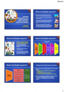
3. KNOWLEDGE REUSE METHOD The process based data driven knowledge reuse method has been reported in a previous paper [10]. The main concepts of the method will be described in this section. The components of the knowledge reuse method are: product, process and task knowledge. It is differentiated from other knowledge reuse methods in two ways: it applies the design process as a core element of knowledge reuse (process based), and it applies an engineering level description of product knowledge (data driven). These methods are appropriate in an evolutionary or variant design scenario. Product knowledge refers to a product model. The product model Develop is structured using an ontology. The content of the product model models, includes specification data such as performance parameters, size, Populate system and target cost alongside an evolving functional representation and structural model. The product model supports early design stages (concept and embodiment). Conceptually it can support an interface with a CAD system in the appropriate design stage. This Validate system is not an implemented feature of the prototype system.
No
Task knowledge refers to ‘how-to’ descriptions of tasks, alongside references to additional information sources to support a task, including manuals, reference data, component libraries, project files, discussion groups, and so on. Task knowledge will also refer to people who have previously carried out a given task, owners of the current task and experts who can provide support.
Validated?
Yes Step 1: access main page
Step 2: access relevant task Supporting knowledge Step 3: access supporting knowledge
Process knowledge refers to the logic by which a design process is defined: task name, expected duration, input and output data, feedback and feedforward loops, and a reference to the task knowledge. The combination of the three knowledge types enables a data driven engineering design process; applying a variety of product data, from concept to evolving engineering data, to the knowledge supported tasks. Top Frame: Title
Product model data
Task name Objective
Step 4: carry out task, store data
Description + hyperlinks to view process input task Left Frame: navigation
Images No
Process complete?
Yes End
Form fields
Image of process objects - components, Data form fields - to resources, etc. as a prompt for task execution and enter task output to aid memory for relevant points.
Process Context Process model view to show previous and next tasks and input and output data sets
Fig. 2: Task page template. Fig. 1: Process based knowledge reuse method. The method for populating and applying the knowledge reuse method is shown in figure 1. Process and product knowledge capture take place, and the system is populated. Task knowledge is also captured and recorded in the system. A validation loop takes place throughout the knowledge capture phase. The knowledge embedded in the system is arranged such that each task is represented in a web page, or task page. Each task page shows a task description, input data, descriptive ‘how-to’ knowledge, links to additional information, and a diagram of the process to provide some context. Data fields are available to record the output of the task. The task page template describing the Computer-Aided Design & Applications, 5(6), 2008, 942-952
945
layout of these elements is shown in figure 2. As the design process is carried out, task knowledge guides the tasks. Data inputs are provided through the task pages. Output data is recorded in the system via the task pages, which is then applied by subsequent tasks. 4. CASE STUDIES The companies that took part in the case studies and the products that were the subject of the knowledge capture are described in this section. The approach to the case studies was as follows: initial discussion took place regarding the research and the company design portfolio and methods to identify a potential case for modelling and analysis. Stakeholders in a design knowledge reuse system were identified as project managers, engineers and designers. The knowledge capture took place using an iterative approach, producing process models and functional structure product diagrams to prompt further discussion and analysis. Modelling supports the construction of complex work practices by enhancing communication and understanding [11]. It has also been proposed that capturing the process as it happens can support the development of formal process models [12], however this approach is only applicable to computer based tasks, so would not capture project tasks that are not entirely computer based. The result of the knowledge capture and process modelling exercise was then applied to the knowledge reuse framework described in the previous section. To demonstrate capability and support the analysis of the knowledge reuse method, in the case of company A, the prototype system was populated using their design knowledge. In the case of company B, a conceptual (paper based) model was developed. 4.1 Company A Company A manufactures vacuum pumps for the global semiconductor industry. The knowledge capture exercise focused on a single component; however the need to identify the product requirements and specifications led to the development of a more extensive design process model.
Fig. 2: Headplate, gearbox side.
Fig. 3: Headplate, stator side.
The knowledge capture exercise with company focused the headplate. The headplate is a cast and machined component that performs several functions. It forms the low vac end of the vacuum envelope. One side represents part of a stator, as shown in Figure 3. The other side is one half of the gearbox enclosure, as shown in Figure 2. The gearbox side houses the shaft support bearings. Lubrication channels are cut into the face above the bearing housings, to direct oil into the bearings. A complex static and dynamic seal arrangement exists between the two sides, to minimise gas and oil travel from the gearbox into the vacuum chamber. The process model is shown in Figure 4, starting with requirements capture and ending with the headplate design task.
Computer-Aided Design & Applications, 5(6), 2008, 942-952
946
Feature 0 Project Team
Requirements Specification
Cartridge Layout
Feature A Engineering Requirements
Feature D Cartridge model
Mathematical modelling
Feature B Product Model
Pump (Rotor) Dynamic model
Bearing selection
Feature G Bearing Spec
Gear selection
Feature H Gear Selection
Motor selection
Feature I Motor Spec
Feature C Shaft dynamics
Headplate design
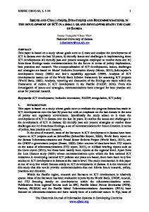
Fig. 4: Company A process model. 4.2 Company B Company B is a large, market-leading manufacturer of domestic heating appliances for the European market. The focus of this study is the UK design group, who are responsible for integrating the various product modules designed at company sites across Europe. The product structure shown in Figure 6 represents the main constituent product modules and their Thermal (T) interconnections. The thermal module is linked to the Gas hydraulics module: pipes from the hydraulic module feed water into a heat exchanger (part of the thermal Radiators module). This heated water is then directed back to Power Hydraulics (H) the hydraulics module, where it is directed out of the unit to provide heating to the environment, either as Hot Water Water hot water or to radiators. The electronics module controls both the thermal and hydraulics modules, Electronics (E) based on a combination of stored programs and input Flue from various environment sensors. Each of the three Case (C) modules is designed by a specialist design group separate to the integration group. Typically, a module is designed for a specific product, however the Fig. 6: Company B product structure. specialist design centres also carry out research and development outside the scope of a specific project. The integration group is responsible for 3D layout of the component modules, as well as defining the various physical connections. Parameters relating to the integration task from a connections perspective include internal and external fittings – as well as the three modules, there are four principle connections with the installation environment: Gas, Power, Water and Flue. There are also external connections to the hot water and radiators (depending on the product type: some products carry out only one of these functions). Connection parameters between these various modules include, amongst others: T:H; W:T; W:H (pipes and fittings) E:H; E:T; E:P (wiring and connectors) Computer-Aided Design & Applications, 5(6), 2008, 942-952
947
4.2.1 Process modeling The company has recently adopted a new product introduction process that describes the whole project, from concept generation through to service handover. The functional perspective of the process shows the documents, procedures and measures that each function must have in place before each stage gate. Because the company had such an extensive process model in place, it was not necessary to create a detailed design process model. The model shown in Figure 7 represents a partial view of the engineering definition process. NPI Team
Manufacturing
R&D
NPI team
Technical, Optical, Price, Handling
Concept: 3D model
Build and test
Technical Requirements Spec
Marketing
Fig. 7: Partial process model. The process model in figure 7 shows the product development activities applied by company B. A marketing specification is fed into concept development stage. A 3D model is then created and validated. This is used to produce a technical demonstrator. The analysis of the technical demonstrator leads to the technical requirements specification if the demonstrator product is shown to be capable of meeting the specifications. One interesting element of this process is the completeness of the initial design stages: at the technical demonstrator (build and test) phase, a 3D model of the product has been developed and the product has been built, tested and evaluated. This takes place in advance of the technical requirements specification phase. The result of this major focus on the early project stages is a greater reliability on the timescale and performance of the later project stages, in which investment in production tooling greatly increases total project spending. A distinction between this model and that of company A is the lack of emphasis on the engineering process. In part this relates to the time spent with each company and so the resulting level of detail of the process model, however it also reflects the complexity of the design problem addressed in each case. 5. ANALYSIS EXERCISE The analysis of the knowledge reuse method (described in section 2) took place using semi-structured interviews and a questionnaire. The participants were asked to make an assessment of the proposed method, based on a view of how this method could be applied to their products and design process. Three scenarios were presented:
Scenario 1: Evaluation of the current situation, in terms of design knowledge reuse (as a baseline, for comparison). Scenario 2: Evaluate the perceived difficulty and value of applying the knowledge reuse method to a new project. Scenario 3: The design team have used the knowledge reuse methodology for a previous project, and now apply it to a new project. Evaluate the perceived difficulty and value.
In each case, the intention was to evaluate potential for design knowledge reuse and the perceived difficulty level. The comparison with the existing situation served a dual purpose of judging the perceived value of the method and judging the existing design reuse capability within the organisations. Each scenario is judged on a 1-5 scale. A mean value of the participant responses is shown. There are two participants in each case. Company A participants were an engineer and a senior designer. Company B participants were a design technology manager and a senior project manager.
Scenario 1 How effective is the current design process? What level of design reuse takes place? What is the potential level of design reuse?
Computer-Aided Design & Applications, 5(6), 2008, 942-952
Company A
Company B
3.5 4 4
4 3.5 4
948
Company A
Company B
Scenario 2 How would you judge the proposed method? Would it provide a benefit over the current method? What degree of difficulty would you expect in using this method?
3 4 5
3.5 2.5 4
Scenario 3 How would you judge the proposed method? Would it provide a benefit over the current method? What degree of difficulty would you expect in using this method?
4 4.5 2
3.5 3 3.5
Tab. 2: Participant responses: mean values. 5.1 Company A During the completion of the questionnaire, the questions and answers were discussed. In addressing scenario 1 and 2, additional comments were provided to explain the values assigned to each scenario. The result is discussed, followed by the comments for each scenario. 5.1.1 Scenario 1 The existing design process performs well, however not at the top level (‘high quality, exceeding specification’). Design reuse is widespread, roughly in line with potential. Team members influence what will happen in terms of design reuse, best practices, and so on: the application of design methods varies widely across projects. Design reuse is improving, and has been applied a great deal in the current project, particularly through the use of predictive tools and knowledge based systems for conceptual modelling and analysis. 5.1.2 Scenario 2 The method is capable of providing benefits, however the implementation is critical. It has the capability to provide a benefit over the existing method. It would be very difficult to implement: high effort, cost and time. The result would depend on the project type. It would also be significantly influenced by the support and ownership of the method – good support would be essential to its success. In this scenario there is a good potential for benefit, with a high risk. 5.1.3 Scenario 2 The knowledge reuse method is capable of improving the design process, with the potential to provide substantial benefit over the current method. 5.1.4 Further comments on the knowledge reuse method It was considered that the methodology could provide significant benefit, with a number of provisions:
Not as just another process to follow: it is important to provide value to the users. The data driven process approach appears to be a potential means to provide that benefit. The method needs to incorporate existing processes, reducing points of contact for reference material or NPI guidance. Provided people engage with it. There are other systems available, such as an online design manual. Not everyone in the design team uses it. Ease of use is important – and users must be able to FIND the system in the first place. Software purchase decisions can be taken locally. A method with such broad scope must be driven from the top. Training would be required, particularly in the initial stages.
Additional features that could improve the implementation of the method were also proposed: It should be possible to browse the product knowledge framework, through links to relevant product subsystems, functions or components. Computer-Aided Design & Applications, 5(6), 2008, 942-952
949
Design rationale for previous product features should be provided alongside test results. Feedback from previous project, especially a record of past mistakes, could be useful in preventing the next project tripping at the same hurdle.
5.2 Company B The participants completed the questionnaires without discussion; they wrote comments in the boxes provided, which were as follows. The questionnaire result is discussed, followed by the comments provided for each scenario. 5.2.1 Scenario 1 The existing design process performs well, however not at the top level (‘high quality, exceeding specification’). Design reuse is moderate, slightly below the potential reuse level. There is a project currently looking at design knowledge and component reuse. This should help future projects. Because of the group structure, group knowledge and components are shared. Design knowledge and historical knowledge could be improved. 5.2.2 Scenario 2 The proposed method could provide some benefit to design, however would not provide significant benefit over the existing method. High effort would be expected in implementation. Design reuse methodology has a limited fit to the current design process. Main areas would be in standard parts. The method would require significant effort and resource. I have no doubt that it would improve design; implementation and buy-in would be the problem. 5.2.3 Scenario 2 The knowledge reuse method could potentially provide significant benefit to design, however would remain comparable to the existing method. Moderate effort would be expected in implementation. We are currently trying to utilise our own version of knowledge reuse, but we need to improve buy-in from other departments. 5.2.4 Further Comments on the Knowledge Reuse Method In both scenario 2 and 3, implementing the method from scratch and applying a populated system with some experience, the views on its effectiveness were very different from the two respondents. One saw a very high potential value, the other perceived the knowledge reuse method to have a very limited potential value. The main area of benefit would be in storing and accessing information relating to standard parts. Implementation of the method was considered as a barrier, however buy-in, or adoption of the method was also recognised as a major challenge. 6. PROPOSED IMPLEMENTATION APPROACH The proposed approach for implementation of the method is shown in figure 1. The first task, represented as a preparation task is: “develop models, populate system”. This task consists of capturing the process, task and product knowledge and populating the system. It was suggested in the case studies that this task would require significant effort. It was also identified that the buy-in was an important element of success: a high effort to implement the method may result in reduced confidence. A common way to overcome this barrier is to run a pilot exercise, in which a sample set is defined and applied to the method to enable a better understanding of how the method can contribute, the actual effort required in development, and whether there are any missing elements. The validation task is an important stage in which changes to the system should be expected, based on user views in terms of the validity of the knowledge as well as the system interface. The remaining process describes the operation of the system: access the system main (web) page, and navigate to the relevant task. Supporting knowledge is provided on the task page: how-to descriptions, links to supporting information and product data. The task is completed, and new product data stored. This process continues until all tasks are complete. 7. PRODUCT KNOWLEDGE SUPPORT REQUIREMENTS The insight gained across the two case studies, combined with the findings from the initial investigation, shows a number of essential elements for design support tools in practical situations. The preliminary investigation highlighted Computer-Aided Design & Applications, 5(6), 2008, 942-952
950
some practical requirements for design support tools: to combine an engineering view with a commercial view; to promote shared understanding of the knowledge content; to improve design knowledge access and retrieval; and to support knowledge reuse for the whole product life cycle, particularly early design. These attributes relate to the knowledge content. The case study investigation has shown several other factors that relate to the emphasis of design support tools in terms of the specific product development focus. These attributes relate to the knowledge context. The contextual knowledge support categories are:
Requirements definition Product function structure development and sharing Performance analysis data Common parts Product layout Regulatory guidelines
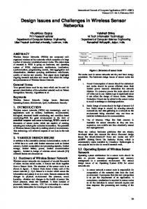
An analysis of the relative importance of these categories can guide the knowledge support strategy, and highlight those areas which require greatest effort and focus. In defining the product for company A, the product requirement definition is crucial. This includes details of the process that the pump will support, required vacuum performance, environment category (such as clean room), customer type, interface data (network connection etc), and key product characteristics. For company B, the definition of the product is also crucial from a marketing perspective, however from a technical perspective there are fewer variables that are less demanding. The product function structure enables both companies to define performance parameters in a modular sense. Company B divides their design effort into distinct modules, whereas company A designs each of the modules in their modular product range in the same group. Modular definition of product function is therefore important to both groups, more so company B. Performance analysis data is applied by both companies in modelling product function in the early stages of development. Company A design vacuum pumps in which manufacturing tolerances are crucial to achieving product function. Company B manufacturing is generally less sensitive to production tolerances. As such, the definition and sharing of data relevant to product performance is of greater importance to company A. There is also a distinction between market types: company A is more sensitive to engineering requirements as they produce a range of products with quite different requirements. Company B has a more stable requirement across their product range. The product performance therefore differs considerably. Common parts and features data is of greater importance to company B, since they operate in a high volume production environment, whereas company A operate medium volume production. Clearly, benefits can be gained in both areas by specifying common parts and features. It is of greater importance to company B to ensure that common parts data are effectively shared in the NPI process. The relative importance of each of knowledge representation types (requirements, function, performance data, common parts, regulatory guidelines and layout data) is displayed in a radar diagram in figure 9. The critical element of product knowledge representation for company A is the definition and sharing of engineering requirements in order to create and assess a product that performs to that specification. The critical element of product knowledge representation for company B is the definition and sharing of a standard component library within a modular design domain. Regulatory guidelines are also a major focus for company B. 8. DISCUSSION Currently, both companies apply the stage gate method for the NPI process. Neither company has in place a data driven (engineering focused) NPI knowledge support method. It has been shown that the needs of each company are different. The major requirement of company A, the definition and sharing of engineering requirements, would be addressed to a large extent by the product knowledge element of the proposed knowledge reuse system. The major Computer-Aided Design & Applications, 5(6), 2008, 942-952
951
requirement of company B, definition and sharing of a standard component library, is not fully addressed by the system in its current state. An additional method to describe a generic product structure is needed as an additional feature of the product knowledge model. This would entail an extension of the design ontology to include standard parts definitions.
Product requirements 6 4 Regulatory guidelines
Product function structure 2 0
Company A Company B
Embodiment (layout) data
Performance analysis data
Common parts / features data
Fig. 9: Radar diagram showing relative importance of knowledge representation types. 9. CONCLUSIONS A design knowledge reuse method that supports product, process and task knowledge has been evaluated in two case studies. The proposed design knowledge reuse method supports the industrial needs identified in the preliminary investigation: to combine an engineering view with a commercial view; to promote shared understanding of the knowledge content; to improve design knowledge access and retrieval; and to support knowledge reuse for the whole product life cycle, particularly early design. Having developed a method to address these general aims, the specific needs of the company are still critical, as the case study analysis shows: implementations of design knowledge reuse methods must consider contextual factors as a critical success factor. The proposed methodology has been shown to support the needs of a company whose primary knowledge support requirement is the definition and sharing of engineering requirements as a means to develop an effective product. The method requires further work if it is to fully support the second company, whose primary product knowledge support requirement is the definition and sharing of a standard component library to support the integration design task and minimise manufacturing costs. 10. ACKNOLWLEDGEMENTS The authors would like to acknowledge the support of the EPSRC through Cranfield University IMRC in funding this research. The support of the case study companies is also greatly appreciated. The authors acknowledge the contributions from the members of the Decision Engineering Centre at Cranfield University. 11. REFERENCES [1] Sivaloganathan, S.; Shahin, T. M. M.: Design reuse: an overview, Proceedings of the Institution of Mechanical Engineers - Part B - Engineering Manufacture, 213(7), 1999, 641-655. [2] Lang, S. Y.; Dickinson, J.; Buchal, R. O.: Cognitive factors in distributed design, Computers in Industry, 48(1), 2002, 89-98. [3] Dani, S. S.; Harding, J. A.: Managing reuse in manufacturing system modelling and design: a value net approach, Journal of Computer Integrated Manufacturing, 17(3), 2004, 185-194. [4] Bohm, M. R.; Stone, R. B.: Representing Functionality To Support Reuse: Conceptual And Supporting Functions, ASME 2004 Design Engineering Technical Conference, Salt Lake City, Utah, USA, Sep 28 2004. [5] Ullman, D. G.: Toward the ideal mechanical engineering design support system, Research in Engineering Design, 13(2), 2002, 55-64. [6] Kwan, M.; Balasubramanian, P.: Process-oriented knowledge management: a case study, Journal of the Operational Research Society, 54, 2003, 204-211. Computer-Aided Design & Applications, 5(6), 2008, 942-952
952
[7] [8] [9] [10] [11] [12]
Tam, S.; Lee, W.; Chung, W. W.; Nam, E. L.: Design of a re-configurable workflow system for rapid product development, Business Process Management Journal, 9(1), 2003, 33-45. Kang, I.; Park, Y.; Kim, Y.: A framework for designing a workflow-based knowledge map, Business Process Management Journal, 9(3), 2003, 281-294. Li, Y.; Shao, X.; Li, P.; Liu, Q.: Design and implementation of a process-oriented intelligent collaborative product design system, Computers in Industry, 53(2), 2004, 205-229. Baxter, D.; Gao, J.: Development of a Process Based Data Driven Engineering Design Knowledge Reuse System, Computer-Aided Design & Applications, 3(1-4), 2006, 109-117. Barnard, Y.; Blok, I.: Gathering user needs for knowledge management applications for engineers in advanced manufacturing industries, 8th International Conference on Human Aspects of Advanced Manufacturing: Agility & Hybrid Automation, Rome, Italy, May 26-30, 2003. Ishinoa, Y.; Jin, Y.: An information value based approach to design procedure capture, Advanced Engineering Informatics, 20, 2006, 89-107.
Computer-Aided Design & Applications, 5(6), 2008, 942-952