ISSN 1744-1986
Technical Report N
O
2010/ 06
Design rationale capture for process improvement in the globalised enterprise: an industrial study A Nkwoca Jon Hall, Lucia Rapanotti
11 March, 2010
Department of Computing Faculty of Mathematics, Computing and Technology The Open University Walton Hall, Milton Keynes, MK7 6AA United Kingdom http://computing.open.ac.uk
ISSN 1744-1986
Technical Report No 2010/06
Design rationale capture for process improvement in the globalised enterprise: an industrial study A Nkwoca Jon Hall Lucia Rapanotti
11th March 2010
Department of Computing Faculty of Mathematics and Computing The Open University Walton Hall, Milton Keynes MK7 6AA United Kingdom http://computing.open.ac.uk
Design rationale capture for process improvement in the globalised enterprise: an industrial study A. Nkwocha · J. G. Hall · L. Rapanotti
March 10, 2010
Abstract Design rationale in software engineering fills in the gaps between the original requirements of a system and the finished product encompassing decisions, constraints and other information that influenced the outcome. Existing research in this field corroborates the importance of design rationale to capture knowledge assets, particularly in the context of the global enterprise, with its increased risk of knowledge loss through staff movement and attrition. Despite this, the practice of design rationale capture and reuse is not as extensive as could be expected due to reasons which include time and budget constraints and lack of standards and tools. In this paper we report on and industrial study which tested the hypothesis that an emerging design approach – Problem Oriented Engineeering – enables the capture of design rationale as the methodological by-product of software engineering activities, hence potentially addresses concerns over cost effectiveness of in situ design rationale capture. Keywords Design rationale · Process improvement · Problem Orientation · Assurance
1 Introduction A Gartner report on IT services [1] projected that almost half of all Fortune 1000 global enterprises would choose to draw business benefits from IT service providers, rather than owning their IT assets. Buying into IT service provision may reduce fixed costs – for instance, there will be a reduction in experienced staff needed – and may free an organisation to focus on their core business without day-to-day IT distractions, but there may be a concomitant increase in exposure to risk – for instance, that the system is of adequate quality, or that the provider will be able to sustain any service level J. G. Hall Department of Computing The Open University, UK E-mail:
[email protected] L. Rapanotti Department of Computing The Open University, UK E-mail:
[email protected]
2
agreement (SLA) in force for the duration of the relationship. With many organisations having rushed to explore the benefits of IT outsourcing, some find themselves moving back to in-house provision. No matter whether the move is in-to-out or out-to-in, one hurdle in the way of change is the difficulties of sharing and/or relocating expertise between two separate organisations. Expertise is achieved as a result of dedicated application within a chosen field, having been exposed to many examples of the problems and solutions that occur therein [6]. It is as expensive to create as it is to maintain, not least because of its tacit nature [20], easily lost at the point of need through staff movement and attrition. Even before industrial trends, many have recognised the importance of expertise expressed in products, processes and practices, but few have been able to actively bottle it: Design rationale [15], it has been suggested, bridges the information gap between the need a system fulfils and its final design. Often described as a snapshot of the decisions taken in reaching the final design [2], it tries to capture the reasoning and knowledge that justify the resulting design [25], including arguments behind the choices made. As such, it may appear that design rationale is the tool for making explicit some valuable tacit knowledge during software development. However, design rationale capture is often not practiced as it can be time consuming and expensive [2] and often places extra burdens on resources with no perceived immediate benefit [16]; specifically, the benefits of recording design rationale are realised by the ability to use the gathered information for further decision making both for the evolution of the designed product and as a basis for the new designs. Therefore, it remains the case that much work on rationale capture and management remains theoretical. A greater uptake may be achieved by demonstrating to design practitioners that rationale management can be achieved as a by-product of design, rather than a bolt-on activity, particularly by providing efficient ways of classifying information and easy methods to create, navigate and retrieve knowledge. If it were easier to capture the rationale for a design, much could be made of it when other changes were apparent. For instance, the change of personnel that might be effected during a transition from out- to in-housing of IT Services might bring with it the possibilities of evolution of the processes and practices in which they were/will be involved. So, a system in which design rationale is captured should also represent that captured information in ways that make possible process and practice reengineering. Based on a study conducted in a real-world organisational setting, in this paper we explore the hypothesis that an emerging design approach – Problem Oriented Engineering (see, for instance, [13, 12, 14]; POE for short) – enables the capture of design rationale as the methodological by-product of software engineering activities. The evidence gathered in the study suggests that POE potentially addresses concerns over cost effectiveness of in situ design rationale capture, and may also yield process improvement. Briefly, POE is a general framework for engineering, including design, in which exploration and validation phases both of problem and solution interlock: exploration of the problem context, its requirements, and possible solutions through traditional modelling and design activities; and validation of assumptions and decisions by stakeholders. Within POE, Assurance-Driven Design ([11]; ADD for short) recognises the need for ongoing management of the risk of inadequate validation during the development process to supplement (traditional) product-driven design methods. Risks that ADD explicitly addresses include: solving the wrong design problem and producing an inadequate solution, where inadequacy is defined with respect to all stake-holders.
3
We note that this includes the motivation for the capture of design rationale, and so it is these characteristics of POE and ADD which are exploited for design rationale management. The paper is organised as follows: Section 2 provides some background; Section 3 gives detail of the study, whose results are analysed in Section 4; finally, Section 5 offers a discussion and concludes the paper.
2 Background 2.1 Design Rationale Management Design Rationale in its simplest form is, [15]: “... the explicit listing of decisions made during a design process and the reasons why those decisions were made.” For software, it should also capture how a system satisfies functional and quality requirements, the reasoning that caused design choices to be made over other options and what type of system behaviour is expected under different environmental conditions [8, 17]. The importance of capturing design rationale in software engineering has been recognised for some time [15], particularly for aiding the development, evolution and support of large software systems whose life cycle would usually involve a large number of programmers, system analysts, project and section leaders and other support staff. With knowledge needed to support such systems distributed between many people, the likelihood of loss due to staff attrition is high. The recognition of the importance of documenting and managing rationale has led to the emergence of industry guidelines aimed at standardising elements and practices to provide a basis to improve cost efficiencies and quality [25]. Notable examples include standards on documenting software architectures, including the IEEE Recommended Practice for Architectural Description of Software-Intensive Systems (IEEE 1471/2000 standard) and Views and Beyond approach to documenting Software Architecture (V&B) guidelines [5]. Capturing knowledge is a step crucial in avoiding loss [23], with its value to an organisation realised when available in a reusable form [4, 2]. A typical example is the evolution of a software architecture due to market pressure or new customer requirements, or simply to develop a new system upon it. In such cases, the information embodied in the architectural design itself is often insufficient to permit direct reuse [16], and it is a costly burden to record sufficient design rationale for reuse. Moreover, practitioners can become resistant if they feel the process of recording is too intrusive [2]. In fact, time and budget constraints on the capture of design rationale was found to be the most common barrier to documenting rationale in a recent survey of design practitioners [25]; the lack of tools to facilitate the capture of design rationale was also cited as a hindrance to recording the necessary information to the practice. The knowledge assets of an organisation include the tacit knowledge of experienced task experts [4] which must be elicited and recorded in a way that can be accessed and used by others. With the chosen representation a significant factor in its reusability [15, 17, 23], the representation that the design rationale should take [7], how to recognise what constitutes a design decision, and how and when it should be captured [17, 25, 15] are important issues.
4
Douglas ([7]) suggests that rationale management should start with the examination of the problem to be solved and should include: a description of issues addressed prior to the decision; a list of the alternative solutions considered; the criteria used in the selection; the argument or reasoning used to justify each alternative; and the decision itself. Regli ([23]) identifies two main approaches as having emerged to aid the capture of design rationale: process-oriented approaches, which capture the rationale as a history of the system being examined; and feature-oriented approaches, which focus on the representation of artefacts in the system. In [3], the authors argue that the use of a process model can assist in guiding decisions that need to be made during the design activity and later provide knowledge that can be used to make decisions. They suggest that the explicit capture of alternatives considered and the rationale behind the choices made can be integrated into a design process model. The design process could possibly be repeated to create a new but similar design or to assess the impact of changing decisions taken during the original design. Among the key information elements involved in rationale capture are: – Decisions, i.e., the design choices made; – Justification for decision(s) taken, i.e., the reasoning, deliberations, criteria for selection and any related argumentation; – Alternatives, i.e., the various trade-offs; – Traceability, i.e., the relationships between layers of information; – Contacts, i.e., all relevant stake-holders. In this paper we will consider these aspects of rationale capture in a real-world organisational setting, with particular attention to reuse and process improvement within the organisation.
2.2 Problem Oriented Engineering and Assurance Driven Design POE is an emerging framework for engineering, the creative, iterative and often openended undertaking of designing and building products, systems and processes. POE sees engineering as a problem solving process in which interlocking exploration and validation steps are carried out: exploration of knowledge and its representation; and validation of represented knowledge. Both involve stake-holders: finders contribute to exploration; validators contribute to validation. Following an engineering tradition [24], POE problems concern the fundamental engineering question of how a solution can be designed to meet the requirements of stake-holders in a real world context. Framing a POE problem is then a process of discovering relevant knowledge pertaining to those problem elements, and from that synthesising the solution. The basic building blocks of POE are: problems, which capture knowledge about the identified need, its context and the designed solution; transformations, which provide discrete problem-solving steps; and justifications, which capture arguments to support stake-holder validation. ADD adds a process view to POE, which recognises the need for ongoing management of the risk of inadequate validation during the development process to supplement (traditional) product-driven design methods. Risks that ADD explicitly addresses include: solving the wrong design problem and producing an inadequate solution, where inadequacy is defined with respect to all stake-holders. Risk mitigation is the outcome of stake-holders’ communication and interaction.
5
Problem Validator
Previous problem validation invalid
1
Most recent problem validation invalid Solution validation indicates problem was invalid
invalid
Problem exploration
valid
Problem validation 2
Problem Finder
Solution exploration
3
invalid
Solution validation 4
valid
Solution Finder
Solution Validator
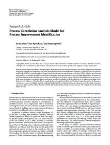
Fig. 1 POE Process Pattern: to move towards a partial solution to a general engineering problem, we first understand the problem better (1), reflecting our understanding of the problem through validation with the problem holding stake-holder (2); use engineering judgement to determine a candidate solution architecture (3), then test the candidate for satisfaction of concerns, iterating if necessary (4).
Proposed by the second and third authors, POE and ADD have been successfully applied to the design of, and design process improvement for, software intensive systems, particularly in the area of high assurance and mission critical systems [18, 9]. Comprehensive and detailed introductions can be found in [13, 12, 14, 11]. Without loss of generality, in the following we will use the term POE to indicate the application of the framework in combination with its ADD process view. Typically, the path to an adequate solution under POE proceeds through applications of the POE process pattern [11], captured in Fig. 1 in a notation reminiscent of UML activity diagrams [21]. The pattern consists of activities, choice points and roles.
2.2.1 Activities In problem exploration knowledge of the context and requirement of the problem (or part thereof) in captured. In solution exploration, knowledge of the solution (or part thereof) is captured. These activities are partial as problem solving may (initially) focus on parts of the context, requirement or solution, rather than on the whole problem.
6
2.2.2 Choice-points The choice points allow validation to affect exploration in determining whether from a current candidate characterisation of the problem the solution may be investigated, and whether from the current candidate solution further problem exploration is appropriate or that backtracking the development – to find another candidate solution or to explore the problem further – should be done. There are many sources of complexity in the POE Process Pattern, some of which will be seen in the case study upon which this paper is based. However, for a detailed description of the various possibilities for, for instance, the interleaving of validation and exploration, and for the combination of the POE Process Pattern – in sequence, in parallel, and fractally – with itself, we refer the reader to [11].
2.2.3 Roles The roles are of Problem Validator, Solution Validator, Problem Finder and Solution Finder, with their respective scopes indicated by shading in the figure. A Problem Validator validates a (partial) candidate problem. Examples include a client, a customer, a regulator. A Solution Validator validates a (partial) candidate solution, and may be, for instance, a chief architect or a project manager. Both Problem and Solution Finders have the roles to begin by trying to understand the context and the requirement, and iterate towards a solution: a designer may assume both such roles. As indicated by the upward pointing arrow that appears in the upper right of Fig. 1, iteration is not always local: it is, for instance, possible that through the failed validation of a solution a previous problem description may be revealed as flawed, even if it has been validated by a Problem Validator – even validators may make mistakes sometimes – or perhaps a validated problem requires a solution beyond the resource level which is available. During the POE problem solving process, design concerns capture issues which are of particular interest to stake-holders, for which risks have to be suitably addressed, and decisions justified and validated. Design concerns are used both as an analytical tool and to provide a focus for exploration and validation activities. Concerns can be associated both with problem elements and the problem solving process. There are many characteristics of POE which make it a suitable candidate for design rationale capture. Its conceptual framework provides guidance as to which information should be collected – the ‘what’ question – through the notion of problem and its constituent parts, and the point at which it should be collected – the ‘when’ question – through its transformational step-wise approach. Moreover, both of the salient views (process-based and artefact-based) and their relations can be captured through POE , including a record of any backtracked decision during development. Last but not least, that design rationale capture is a by-product of design follows from POE interlock of exploration and validation steps during development. In the following sections we will demonstrate how these concepts came together in our study for design rationale capture within a real-world organisational setting.
7 Table 1 Summary of key terms Term
Description
Mortgage Servicing
Managing mortgage loans – interest accruals, billing, collecting due payments, redemption of loans etc
Financial Services Authority (FSA)
Regulatory body for financial institutions
Mortgage Servicing Software (or Servicing Software)
Software used in servicing activities
Triage Document
A form used to report details of a production issue
3 The study and its organisational context The context of the study is the first author’s organisation, a UK based subsidiary of an American financial organisation (the Company), with business, systems and technical analysts based in the UK, technical architects in the US and development staff in India. Relevant key terms and stake-holders are summarised in Tables 1 and 2. The company supplies a Mortgage Servicing Software package to its Client, a product that manages loan accounts once mortgage payments have been made by the Client’s customers. The software facilitates business tasks such as payment calculation and processing, account queries, early redemption, correspondence, interest rate change and customer billing. The company also provides support and assists in the resolution of issues that arise during the use of the supplied software. Recently, the company lost a number of subject matter experts but retains a contractual obligation to provide support to the Client to enhance and maintain the supplied software stack. This motivated the company to investigate through this study the capture of design rationale during Client’s issue resolution. As many organisations face such losses, the success of our case study takes on increased importance. The case study also provided opportunities to consider how the application of POE techniques could improve the current issue resolution process. Process improvement is also an issue faced by many organisations.
3.1 Relevance questionnaire A pre-study questionnaire was designed to gather evidence that the perceptions and practices of staff in the case study organisation were in line with those reported as typical of the industry in the design rationale literature, particularly [17, 25, 23], hence providing a degree of confidence that generalisations could be drawn from the study. Information types and sources, and reuse factors mentioned in the questions were identified both through reading the literature and from information related to recent organisation’s off-shoring and restructuring processes. A questionnaire was chosen over face to face interview as it was considered the best means of sampling opinions of staff members globally dispersed over three continents. Closed questions using Likert-style scales were used. Space was also given for more discursive comments. The questions were aimed at gathering information of respondents’ experience and work functions, and assessing opinions of how access to design rationale
8 Table 2 Summary of key stake-holders Stake-holder
Description
Client
The mortgage institution managing customer mortgages
Financial Institution
Also the Client
Customers
Patrons of the client organisation whose mortgages are being managed
Servicing Software Company
Company that supplies and maintains mortgage servicing software for the client. The case study is based in this organisation
Software Supplier
Also the Servicing Software Company
Client Production Support Team
Group of individual on the Client side tasked with dealing with issues raised in regards to application software being used in day to day business activities They keep contact with the Client, understand the workings of the application system and the platform that it runs on, provide the initial information on issues and communicate with business decision makers within the organisation when questions arise of a business policy nature
Supplier Production Support Team (SPST)
Groups of individual on the Supplier side tasked with dealing with issues raised in regards to application software being used in day to day business activities. They keep contact with CPST, assign work to the development and mange releases of solutions to the Client
Application Architect (AA)
Reviews a solution to assess if solution complies with standards
Product Assurance Team
Ensures the quality of the provided solution
Mortgage Business Manager
Makes the final sign-off decision
IT Management
Makes the decision on whether the solution will be implemented to production
Offshore Development Team (DT)
Group of individual on the Supplier side tasked with developing software
information affected their work. The questionnaire was sent out by email to international employees and by hand to UK staff. A covering letter was included requesting assistance a definition of design rationale and instructions for filling the questionnaire. Although the number of respondents was small (9 out of 15 invited), their spread within the organisation in terms of diverse functions and years of IT experience was considered sufficient to provide a suitable representative sample within the division of the organisation in which the first author works, which is made of 10 onshore (UK), 20 offshore (India) and 3 offshore (US) staff. All of the respondents had at least 2 years experience in IT and two of them had over 10 years. The respondents covered the following job functions: Development, Support, Business and Systems Analysis, Product assurance (Testing), and Project and Senior Management. The conclusion was that the perceptions of staff in the case study organisation were in line with those reported in literature, hence the organisation constituted a representative industrial context for the study. A detailed analysis of the responses can be found in [19].
9
3.2 Issue resolution process Figure 2 captures, as an activity diagram with swim lanes, the process for handling issues reported to the Software Supplier, used by the organisation at the time the study was conducted. A brief description follows. When an issue is found in the Client’s use of the Company’s applications, a Triage Document is raised to describe the problem with information included that may assist in tracking down its cause. The reported issue is given a priority by the Client (low, medium, high) that governs the timeline for response and solutions, based on servicelevel agreements. Once the Triage Document is received by the Supplier’s Production Support Team, an incident number is generated and used to track the issue. The information is checked to see if it is sufficient for the investigation to progress. Further discussions may be held between the Client and Supplier Production Support Teams to agree a) which issues lie with the application software and b) an approach for dealing with the issue. Additional clarification may be sought from the Client from which the issue report originated. The clarification may be in the form of screen shots of the application error, data extracts, event logs and example scenarios. When issues are agreed between Client Production Support Team (shortly, CPST) and Supplier Production Support Team (shortly, SPST), they are analysed and solution approaches proposed by the development and architecture resources assigned to the issue. The proposed solutions are discussed with the CPST. Once agreement is reached on a solution approach, it is developed and tested. On completion of development and testing, the solution is packaged by the SPST with release notes and a test report, and delivered to the CPST. Subsequently, the CPST validate the delivered package, perform some further tests in collaboration with the Client, and may either return it for rework if it is unsatisfactory or implement it to the production systems if satisfied with the results.
3.3 The Problem The problem chosen for our study, which we call the Valid Amounts Problem (the Problem), concerns the correction of billing errors. Briefly, customers are billed based on the terms of the loan, payments received and interest rate changes, amongst other factors. Discrepancies in the figures used for calculation can lead to incorrect amounts being billed and/or held as balances against a loan account. As a financial institution regulated by the Financial Services Authority (FSA), the Client must be able to explain the reasoning behind their charges and services and also provide their customers with information on these factors sufficient to remain compliant. The impact of such errors, that the Client can be held in breach of statutory regulation, makes their resolution high priority. The resolution of such issues is assisted by the Software Supplier, who may deliver code and/or data fixes. The Problem was chosen as a case study representative [26, page 41] of how issues are investigated and resolved in the Company. Also, as a member of the SPST, the first author could secure adequate access to background information, documentation and the stake-holders for the issue. The problem also needs a resolution that involved some design activity and therefore an opportunity to capture design rationale. The study was conducted in real-time, with POE applied to the resolution of the issue.
10
Client
Report issue and give priority
CPST
SPST
DT, AA & PA
Raise Triage Document
Elaborate info
✘ ok
✔
Analyse issue
Propose solution
ok
✘
✔ Implement, test and QA solution
Package solution and test report
Test and validate
ok
✘
✔
Deliver solution
Fig. 2 The process originally followed for handling Client’s issues. Notation: swim lanes represent stake-holders, rectangles are activities - sometimes involving multiple stake-holders, and diamonds are choice points. The process starts with the Client raising an issue and ends with the Client being delivered a solution.
11 Table 3 POE role assignments Role
Stake-holder(s) who played the role
Problem Validator(s)
The Client, the CPST, and the UK SPST
Solution Validator(s)
The Client, the CPST, the UK SPST, the Application Architect (AA), the Product Assurance Team (PA), the Mortgage Business Managers, with Senior IT Management providing for issue escalation
Problem Finder
The SPST and the CPST
Solution Finder
The SPST and the Off-shore Development Team (shortly, DT)
3.4 The Study
POE was applied to the Problem in the context of the Company’s established issue resolution process. Guided by the POE process pattern (see Fig. 1), problem exploration steps were carried out to gain a better understanding of the problem, followed by validation of the understanding with the relevant problem holding stake-holder(s); while solution exploration steps were used to identify a solution design which was then validated to ensure satisfaction of requirements and concerns. The pattern was repeated where necessary, with backtracking, until a suitable solution was reached. The approach required matching stake-holders to POE roles, as indicated in Table 3. It also required matching process activities to exploration and validation steps (we will return to this point in Section 4.2). In Fig. 3, a POE design tree summarises the steps followed in the case study to reach a successful design: on the left hand side there is the successful design tree; on the right there is a backtracked branch which was followed first but that did not result in a adequate design. The various problems Pi uncovered in the case study (e.g., P1) are summarised in Table 4, with derivation of one from another indicated by dotted arcs, starting at the bottom, where the black dot indicates the start of the process, and proceeding towards the top. Horizontal lines indicate POE transformations, annotated with their justification (e.g., J1) and related validation activities; a tick next to a validation activity indicates that it was successful: there is a single unsuccessful validation requiring backtracking in the right branch; this is described more fully later in the paper. By convention, in the diagram problem validation is represented to the right, while solution validation to the left. Justifications were the means to record, among other information, design rationale and risks; validation activities involved relevant stake-holders. In what follows we will provide a detailed presentation of the initial transformations in this process in order to illustrate how POE was used for rationale capture and validation. We will then provide a brief summary of the remaining steps; for the interested reader, a more detailed description of the case study can be found in [19].
12
✔
Solution Validation
J4.1
✔
Solution Validation
P4.1
J4.2 P4.2
✘
Solution Validation
P4
✔
J2.1 ✔
Solution Validation
J2.2 P2.2
P2.1 J4 P2
P3
✔ ✔
Solution Validation
Solution Validation
Solution Validation
J2
J3 P1
J1
Problem Validation
✔
Fig. 3 Design tree for the Problem: to the left, the successful design tree; to the right, a prior unsuccessful branch which led to backtracking Table 4 Problems Name
Description
P1
the initial Problem
P2
the Problem with two solution sub-components (Mortgage Processing (Calculations) (P2.1) & Loan Balances (P2.2))
P2.1
the Mortgage Processing (Calculations) co-design sub-problem
P2.2
the Loan Balances co-design sub-problem
P3
the backtracked Problem with one solution sub-component (Loan Balances (P3))
P4
the Loan Balances Problem with two solution sub-components (Expected Values (P4.1) & Adjustments (P4.2))
P4.1
the Expected Values co-design sub-problem
P4.2
the Adjustments co-design sub-problem
3.4.1 Notation The graphical notation introduced by [22, 10] is here used to represent problems, their transformation and validation1 . The general justification template described in [9], was is here used to document justifications. A summary of the POE notations for the representation of problems is given in Fig. 4. 3.4.2 Problem Exploration The purpose of problem exploration is to capture details of the problem, its context and requirements. The initial problem details were provided by the CPST in the form of a 1 The formal mathematical notation of [13, 12, 14] was deemed inappropriate in the business setting of the case study.
13
{shared phenomena}
{requirement phenomena} Solution
Context domain
Requirement
Fig. 4 POE notation for the representation of problems: context domains as undecorated rectangles; solutions as decorated rectangles; requirements as ellipses; phenomena shared among domains, or domains and solutions, and phenomena mentioned by requirements as arc annotations.
Triage Document describing the problem and other useful information. As a member of the SPST, the first author checked details in the Triage Document to establish that it was adequate as the basis of further investigation. Additional examples of the issue and clarifications were obtained from the Client. Problem exploration was used to examine the information on the Triage Document by the SPST. By applying POE domain and requirement interpretation transformations [13, 12, 14] the Problem model shown in Figure 5 was derived.
{Formulae, Calculations, Balances, Bill amounts} Servicing Software {Ba
Valid Amounts lan
Accurate billing
ces
,B ill a
mo
Balances
unt s}
Customers
Client {Balances, Bill amounts} {Balances, Bill amounts}
Fig. 5 P1: The initial Problem model
There is an explicit requirement to discharge justification obligations for each POE step: these correspond to various design concerns which arise in the execution of a step. Examples include the validity of descriptions introduced with respect to their real-world counterpart, and the feasibility of a chosen solution architecture. Justifications record such concerns together with all identified risks, some evidence of the action(s) taken to address them and any related stake-holder validation sought. The justification for the interpretations leading to P1 is given below, obtained by applying the template of [9] to the information in the Triage Document: descriptions and phenomena of the problem, and concerns, claims and evidence of their validity are included in the justification. The main concerns emerging during problem explorations have to do with the validity of the context and requirements descriptions. Context validity is about making sure that our understanding of the context correspond to the reality, so to avoid erroneous assumptions on which the designed solution may rely upon. Therefore addressing this concern means managing the risk of neglecting or misunderstanding context properties, or making unwarranted assumptions. Requirement
14
validity is about making sure that our understanding of the requirements corresponds to the real need, that is managing the risk of addressing the wrong problem. Step Id:
Initial Problem Exploration leading to P1
Justification J1 : An initial characterisation of the Problem. The behaviour of interest is the calculation of amounts to be billed to customers. The servicing software uses account balances to calculate due payments and pay-off balances for loan accounts. The Client has identified that some balances on loan accounts are incorrect. Where the balances are incorrect, the calculated amounts may also be affected. Descriptions & Phenomena:
Here are the initial context and requirement descriptions:
Name
Description
Accurate Billing Requirement
That customers are correctly billed for the mortgage loans that they have with the Client
Valid Amounts
The solution that is needed to ensure that customers are accurately billed
Client
The financial institution managing customer mortgages
Customers
Customers whose mortgages are being serviced
Servicing Software
Software used for servicing mortgage loans
and here are their phenomena: Name
Description
Calculations
Application of interest and other factors to produce a figure that the customer should be billed for their loan
Bill Amounts
The amounts the customer is advised to pay for a named period (usually monthly)
Balances
Total amounts for each mortgage loan
Formulae
Formulae used to calculate due amounts
Concern: Problem Validity Status: Pending Claim: This is a valid initial characterisation of the Problem, its context and requirements. Risks: Insufficient or inaccurate information provided for problem solving.
The validity concern, raised during exploration, remained in the pending state until problem validation is concluded, discussed in the next section. 3.4.3 Problem Validation Problem validation transfers the risk of misunderstanding a problem from Problem Finder to Problem Validator; thus is an agreed problem-to-solve arrived at. The consequences of an unvalidated, or an incorrectly validated, problem description could be a solution that solves the wrong problem. This might impact Client confidence, for instance that the Software Supplier can provide adequate solutions, and have resources implications, viz. the time and effort expended designing, developing, testing and delivering the wrong solution. Visibility of the problem validation requirements
15
and description to both client and supplier ensures that both are aware of what is to be solved by the exercise; problem validation acknowledges this shared understanding. Problem validation dealt with the need of the SPST, in the role of Problem Finder, to ensure that sufficient detail was available for further analysis of the issue. The SPST reached the initial description of the Problem from the Triage Document, clarification emails and face to face meetings with the Client and CPST. The Triage Document was reviewed by the SPST, and where necessary, gaps in the provided information were dealt with through follow up. Step Id:
Problem Validation of P1
Concern: Problem Validity Status: Discharged Claim: This is a valid initial characterisation of the Problem, its context and requirements. Argument & Evidence: The information provided on the Triage Document was examined by the SPST and additional clarifications supplied by CPST and Client as requested. The information was assessed and deemed sufficient for further investigation. The context and requirement interpretations were deemed to represent adequately the information as reported in the Triage Document. Risks: Insufficient or inaccurate information provided for problem solving.
Figure 6, shows the validated initial Problem. The stake-holders involved were SPST, CPST and the Client, with the key validation artefact an adequately populated Triage Document. The symbols represent: the level of risk, on a scale low to high; and the status of the validation, discharged in this case. This convention is used to represent validation steps in the case study. The risk in this step is shown as fairly high as there is a high risk of the problem not being correctly understood if the Triage Document is unclear or inadequately detailed. This risk must be dealt with before progressing to issue resolution. 3.4.4 Solution Exploration Consideration of the solution led to the Valid Amounts domain to be structured into two related components, Mortgage Processing (Calculations) and Loan Balances, as shown in Figure 7 and captured in the step justification below. The main design concern in this step is solution validity: making sure that the chosen solution can meet the established requirements in context, hence mitigating the risk of designing an artefact that will not solve the problem. Step Id:
Solution Exploration applied to P1 leading to P2
Justification J2 : Calculations are performed on balance data held for loan accounts to produce billing data for customers. The calculations are defined based on business rules and processes of the client company to produce formulae which are applied to the balances and amounts held for the accounts. There are two parts to the Problem: – looking at the calculations in mortgage processing: if any formula is not correct for particular scenarios (business rules, conditions) then the result will be invalid amounts for billing; and – looking at the loan balances: if any of the balances held on the Loan Account are incorrect then even if the correct calculations are applied, the resulting amounts for billing may be incorrect.
16 {Formulae, Calculations, Balances, Bill amounts} Servicing Software {Ba
Valid Amounts lan
ces
,B
ill a
mo
Balances Accurate billing Problem Validity
unt s}
Customers
Client {Balances, Bill amounts} {Balances, Bill amounts}
SPST, CPST, Client
J1
Triage Document
L
H
✔
Fig. 6 Problem validation of P1, with stake-holders SPST, CPST and the Client, and the Triage Document as key validation artefact.
Valid Amounts Mortgage Processing (Calculations) {Formulae, Calculations, Balances, Bill amounts} Loan Balances
Fig. 7 Solution interpretation of Valid Amount into two components
Descriptions & Phenomena: Following from the above, the corresponding solution components and their descriptions are:
Name
Description
Valid Amounts
The solution that is needed to ensure that customers are accurately billed, made of two components: Mortgage Processing (Calculations) and Loan Balances
Mortgage Processing (Calculations)
The processing, rules and formulae applied to the loan balances on a loan account
Loan Balances
Amounts held for a loan account that are used to carry out calculations: principle balance, interest rate, arrears amounts, prepaid amounts, etc.
and here are their phenomena:
17
Name
Description
Calculations
Application of interest and other factors to produce a figure that the customer should be billed for their loan and adjust the balances held for the customer
Bill Amounts
The amounts the customer is advised to pay
Balances
Financial figures relating to loan accounts
Formulae
The methods and calculations applied to generate billing amounts and update account balances
Concern: Solution Validity Status: Pending Claim: This is a valid solution to satisfy the requirement in its context, that is an implementation based on this design will lead to valid amounts being billed to customers. This is necessary for the Client organisation to ensure that Customers remain satisfied, and compliance requirements of the industry ombudsman, in this case the FSA, are met. Risks: If the requirement is not met: Customers will continue to be charged incorrectly and are likely to become dissatisfied; and Customers will not be charged in line with the terms that they have been told, leading to compliance issues for the Client.
3.4.5 Solution Validation Architectural validation discharges the concerns related to this architectural choice by exposing evidence and arguments to relevant stake-holders. Architectural validation was obtained addressing the validity concern as indicated in the step from P1 (initial problem) to P2 (chosen solution architecture) in Figure 8 and detailed below. In this case, validation was performed the SPST using the Triage Document as the main artefact to guide validation of the architectural design.
Valid Amounts Mortgage Processing (Calculations) {Formulae, Calculations, Balances, Bill amounts}
{Formulae, Calculations, Balances, Bill amounts}
Balances
Servicing Software Loan Balances {Ba
Solution validity
lanc
e s,
Bill a
mou
Accurate billing nts}
Customers
Client
{Balances, Bill amounts}
{Balances, Bill amounts}
SPST
J2 {Formulae, Calculations, Balances, Bill amounts}
Triage Document
Servicing Software
L
H
{Ba
✔
Valid Amounts lan
ces
,B
ill a
mo
Balances Accurate billing
unt s}
Customers
Client {Balances, Bill amounts} {Balances, Bill amounts}
Fig. 8 Solution exploration and validation leading to P2
18
Step Id:
Solution Validation of P2
Concern: Solution Validity Status: Discharged Claim: This is a valid solution to satisfy the requirement in its context, that is an implementation based on this design will lead to valid amounts being billed to customers. This is necessary for the Client organisation to ensure that Customers remain satisfied, and compliance requirements of the industry ombudsman, in this case the FSA, are met. Argument & Evidence: The Valid Amounts domain represents the data held for accounts and the rules/processes applied to that data in order to manage them. The invalid billing amounts being charged to the customer result from either an issue within the Mortgage Processing (Calculations) domain or within the Loan Balances domain. Separating the problem in this way allows for the root cause (entailing application code fix) and effect (entailing data fix) of the issue to be dealt with individually if required, and is in line with normal issue resolution practices. Both aspects need considering in order to solve the Problem, as fixing the calculations may not result in the balances being corrected and fixing the balances may not prevent reoccurrence of the issue. Therefore, the two parts of the solution require some co-design. Risks: If the requirement is not met: Customers will continue to be charged incorrectly and are likely to become dissatisfied; and Customers will not be charged in line with the terms that they have been told leading to compliance issues for the Client.
3.4.6 Further Solution Exploration Further solution exploration of the identified two solution sub-components was carried out leading to two corresponding sub-problems: P2.1 and P2.2 of Figure 3. We briefly discuss such sub-problems in this section and explain how their validation process led to backtracking of the design process. Full detail of the analysis can be found in [19] Exploring the Mortgage Processing sub-problem (P2.1), resulted in further decomposition of the solution domain into two components, corresponding to the two processing modes which can be used to change loan accounts, that is: – Interactive: carried out by a user via screen entry; and – Batch: bulk handling of accounts offline. In the provided triage information, some functional areas were identified for further investigation as possible root causes of the problem. These were: manual adjustments and redemption activities in interactive processing; and billing in the batch processing. Here is a summary of the justification concerns which emerged during solution exploration and which address both the primary risk of an invalid solution, and the secondary risks of compliance and customer satisfaction. Step Id:
Solution Exploration of P2.1
Concern: Solution Validity and Feasibility Status: Pending Claim: A solution of the Mortgage Processing sub-problem would eliminate re-occurrences of the issue, hence, it is considered to be a “strategic” approach to solving the issue. Argument & Evidence: Addressing root causes and providing fixes to resolve them would stop the problem re-occurring. Root causes can occur either during interactive or online processing when: formulae applied are either not correct or applied incorrectly;
19 constraints imposed by business rules are not applied correctly; validations carried out internally or on user interface may be deficient. Also, identifying commonalities between affected accounts could lead to automated resolutions for the problem. The advantages of this approach are: little or no manual intervention is required once in place; the root causes creating the issues will be investigated and eliminated from the system thereby restoring data integrity; automation could significantly reduce the amount of time required to eradicate the problem and its effects. Risks: Inability to identify and fix all root causes; longer period of impact to customers; balances are not fixed by addressing root causes. Concern: Compliance Status: Pending Claim: This solution will result in the Client meeting its compliance obligations. Argument & Evidence: Resolving the root causes of the issue will prevent further occurrences, but further intervention may be required as it may not actually fix the balances that are incorrect. Risks: Balances not fixed by correcting root causes. Concern: Customer satisfaction Status: Pending Claim: This solution will result in reduced impact to customers. Argument & Evidence: Impact is reduced as further occurrences of the issues will be prevented; the customers already impacted may still require further intervention. Risks: Customers may be impacted for longer whilst root cause is investigated and the solution being developed; amounts may still need correcting after the root cause has been addressed.
Exploring the Loan Balances sub-problem (P2.2) also led to two parts to the solution to be identified: – Expected Values domain, which encompasses the correct balance amounts provided by the Client’s Spreadsheet; and – Adjustments domain: the functionality to apply to differences between the actual and expected values to correct the balances; the incorrect amounts would be reset using figures specified by the Client’s business staff.
Step Id:
Solution Exploration of P2.2
Concern: Solution Validity and Feasibility Status: Pending Claim: Solving the Loan Balances sub-problem would address the balance data held on accounts using a fix program to minimise the impact to customers in the short term, hence, it is hence considered to be a “tactical” approach to solving the issue. Argument & Evidence: The main impact of the Problem is to balances on the loan accounts. This solution would correct the amounts removing that impact. Producing the correct figures to be used and proving how they were calculated is accomplished using a complex spreadsheet template manually populated with the financial figures from the application system. These figures are the checked and the final figures to be used have to be signed off by Business stake-holders before the fix can be applied to production data. The advantages of this approach include: it allows the Client to target and correct most impacted Customers; the generated spreadsheet provides the required proof as required by the regulatory body for the amounts arrived at; the quick turnaround means the issue can be addressed with the required urgency. Risks: High level of manual activity, leading to a long projected timeline to fix all the identified accounts; possibility of introducing new errors; root causes are not addressed so customers may be impacted again, leading to the number of affected accounts increasing over time.
20 Concern: Compliance Status: Pending Claim: This solution will result in the Client meeting its compliance obligations. Argument & Evidence: Customers may have to be advised of changes to their account to resolve this problem in order to remain compliant. The spreadsheet used to generate the expected values serves as a validation and sign-off artefact for the business and provides proof that can be used to show compliance. Risks: Root causes are not addressed so issue may re-occur. Concern: Customer satisfaction Status: Pending Claim: This solution will remove impact to customers. Argument & Evidence: This solution removes the impact to customer loan accounts resulting from the Problem as the balances and billing amounts are corrected. Risks: High level of manual activity may cause delays; root causes are not addressed so customers may be impacted again.
3.4.7 Further Solution Validation All concerns raised in the exploration of P2.1 and P2.1 were then addressed through solution validation. The solution validity and feasibility concern was discharged by the Application Architect, who validated the two proposed solutions, and established that they addressed the problem (validity) and were within the capabilities of the company to deliver (feasibility); the AA also established that they conformed to standards. The two solution options were then presented for further validation to the Client and CPST. Note that this latter step was added to the process as a result of applying POE : we will return to this point in Section 4.2. The Mortgage Processing (Calculations) “strategic” solution although meeting the requirement to produce valid amounts, was rejected at this point by the Client having examined the compliance and customer satisfaction concerns and their potential risks. In particular, the Client concluded that: this solution may not resolve the compliance issue without further intervention, i.e., the cause is resolved but the effect remains; customer impact is not addressed in the first instance; there is a difficulty in determining if all root causes have been discovered and fixed; the time scales for discovery could prove to be unacceptably long. It was also observed that some of the root causes were being addressed under other reported issues, outside the scope of this problem. On the other hand, the “tactical” Loan Balances solution was accepted by the Client. In particular, this solution was deemed to resolve the compliance issue by: ensuring that balances are correct, with the Calculation Spreadsheet providing a documented audit together with a report of the changes made; and addressing customer impact in the first instance. There is still a risk of more customers being impacted since the root causes of the issue are not addressed, but as this solution can be applied repeatedly to affected accounts, this risk was considered acceptable. 3.4.8 Remainder of the development As a result of the Mortgage Processing (Calculations) strategic solution being discarded, the design process was backtracked to the initial Problem for which a single component solution architecture was then chosen, as illustrated in Figure 9: compared
21
to the previous solution architecture of Figure 7, this new solution assumes mortgage processing as a given, with only the Loan Balances problem to be addressed. As a side effect, the risks associated with the validity of a solution based on this new architecture are only partially mitigated: the residual risks of more customers being impacted since the root causes of the issue are not addressed remain, with an understanding that the Client is willing to accept such risks.
Valid Amounts Mortgage Processing (Calculations) {Formulae, Calculations, Balances, Bill amounts} Loan Balances
Fig. 9 Single component solution architecture for Valid Amount after backtracking
From this point onwards, the Loan Balances problem analysis was replayed in the same way as explained in the previous section, with its identified subproblems (Expected Values, P4.1, and Adjustments, P4.2) then successfully solved. This led to the conclusion of the design process, as indicated in Figure 3.
4 Analysis of the results In this section, results from applying POE to the Problem are considered in the light of design rationale capture and reuse.
4.1 Rationale Capture The information gathered during the case study was examined based on the design rationale elements identified from the literature and summarised at the end of Section 2.1. The findings were that all the identified elements were recorded during the case study leading to the conclusion that the essential elements of design rationale are captured when solving a software problem using POE . Here is a detailed account, using examples from the case study to describe how the information matches the identified elements. A mapping of the design rationale elements onto POE is given in Table 5. – Decisions: Design choices are recorded in POE in validation steps. An example of this was observed in the selection of the tactical Loan Balances solution over the more strategic Mortgage Processing option in the solution validation step associated with P2.1.
22
– Rationale for decisions: The generalised POE justification template [9] specifies that arguments and evidence be included to substantiate claims about design concerns being met (or not as the case may be). Design choices are guided by the concerns in POE and the arguments and evidence provided form the basis for explaining why those decisions were taken. This was observed in the case study where the need to meet the compliance concern recorded in justifications was instrumental in choosing the Loan Balances solution. – Alternatives and trade-offs: Solution exploration may result in different potential solutions being identified. There were two possible solutions identified for the Problem: a compromise was made in selecting the Loan Balances solution, electing to leave the root causes to be solved at a later date in favour of satisfying compliance and customer satisfaction concerns quickly. – Suitability: Transformation steps are guarded by justifications in POE and must be discharged to establish the adequacy of the resulting problem to stake-holders. Also any proposed solution must be validated with relevant stake-holders to establish that they are fit for purpose [11], with justifications building the adequacy argument for the resulting solution. – Constraints: Constraints are captured in design concerns, like the compliance concern, which imposed a constraint that had to be satisfied for by the chosen solution. Other constraints may derive from properties of the problem context, explicitly captured in context descriptions. – Assumptions: Similar to constraints, assumptions are recorded in many ways, from the explicit descriptions of context domains, requirements and architectural solutions, to the articulation of concerns and their risks in the justifications of transformation steps. All assumptions are visible for scrutiny and validation to stakeholders. This can be seen throughout the case study. – Status: Status information is explicitly recorded against each concern expressed in a justification, reflecting the position of each transformation step within the POE process of intertwined exploration and validation activities. – Complexity of design: Colwell (2005) describes design complexity as a function of the number of ideas that must be considered simultaneously, the duration that they must be considered and the combination of these two factors. Many POE tools help one deal with design complexity, including the identification and separation of exploration and validation activities, of problem elements and their relationships, and of distinct concerns associated to each design step. Such tools allow the designer to focus at any one time on distinct parts of a problem, thus limiting the design ideas that need to be considered in one go, while still providing ways of piecing all elements of problem solving together, hence addressing the overall complexity of the design. – Issue descriptions: Explicit descriptions are required by POE in all exploration and validation activities in order to cover a wide range of design issues of interest to stake-holders. Examples from the case study, include specific concerns in justifications, such as validity or compliance, and the Triage Document from which the initial model description of the Problem was derived and then validated by the SPST. – Traceability: Traceability is a by-product of the POE requirements that explicit problem models, with associated descriptions, be produced, that explicit step justifications be provided and validated, that key stake-holders be identified and associated with validation problems, and that problem solving should proceed in a
23 Table 5 Elements of Design Rationale and their mapping onto POE Element
POE equivalent
Decisions
Design choices and their validation, explicitly captured through exploration and validation steps
Rationale for decisions
Claims, arguments and evidence associated with concerns in justifications
Alternatives and trade-offs
Solution exploration and backtracking
Suitability
Stake-holder validation of concerns identified in justifications
Constraints
Descriptions of problem elements; claims, risks, arguments and evidence associated with concerns in justifications
Assumptions
Descriptions of problem elements and validation artefacts
Status
Tracked in justification concerns
Complexity of the design
Problem diagrams, design trees, process pattern
Issue descriptions
Claims, risks, arguments and evidence associated with concerns in justifications; validation artefacts
Traceability
Problem diagram, design trees, process pattern
Contacts
stake-holders roles, i.e., problem finder, problem validator, solution finder, solution validator
step-wise manner with design trees capturing relationships between problems. Each of these traceability aspects can be observed in the case study. – Contacts: The four roles in the POE process ensure that relevant stake-holders are identified and involved in the process at appropriate steps. Although for the purposes of confidentiality, specific names have not been included for the stakeholders in the case study, they have been identified by their role in the organisation involved (see Section 3, Table 2). In a real life situation, the names and contact details would be noted alongside their role assignments.
4.2 Rationale Reuse The other aspect of interest to this research was to establish whether the design rationale captured with POE could be reused. It was observed that using POE to solve a problem imposed a formal structure on the flow of information used in reaching a solution. The organisation process of Figure 2 in Section 3 was re-examined in the light of the POE process pattern, leading to the revised process diagram of Figure 10. The latter was derived by organising process activities according to the POE process pattern phases, that is problem and solution explorations and validations; activity labels were kept consistent as much as possible, although as a result of applying the POE process pattern, some of the original activities had to be separated into their exploration and validation components, and some extra validation was included in the revised process. More precisely, by following the POE process pattern, in order to carry out validation there needed to be formal hand-off point between main activities in the case study. For example, the result of initial problem exploration, had to be validated with
24
Problem Validation
Problem Exporation
Solution Exporation
Solution Validation
[Client] Report issue and give priority
[CPST] Raise Triage Document
[SPST, CPST, Client] Elaborate and Complete Triage Document info
[SPST, CPST, Client] Validated Triage Document
✘
✔
[SPST, DT] Analyse issue
[SPST, DT] Propose solution
✘
[SPST, AA] Validated proposed solution
✔ [SPST] Prepare problem specification document
✘
✔
[DT, AT] Implement and test solution
✘
[PA] QAed implementation
✔
[SPST] Package solution and test report
✘
Deliver solution
[CPST, Client] Validated problem specification document
[Client, CPST] Tested solution
✔
Fig. 10 The process followed for handling Client’s issues revisited in the light of the POE process pattern. Notation: swim areas represent phases of the POE process patterns, rectangles represent exploration activities, and diamonds validation activities. Each activity’s label starts with an indication, in square brackets, of the stake-holders involved.
25
an artefact of some form to be examined: in the first validation step, this was the completed Triage Document. It was observed that in the original process, Client validation was missing between this initial validation and that of the implemented solution, and this was found to be a gap in the Software Supplier’s process: in their normal day to day processes, communication following the acceptance of the Triage Document was transient, centred on emails and face to face discussions; this allowed critical design decisions to be taken about the solution that were not evident to the Client until the solution had been delivered. The lack of a signed-off proposed solution also allowed the Client to introduce changes at late stages of development and reject solutions as unsuitable after delivery. As a result, a new document was introduced during the study, the Problem Specification document (see activities with a grey background in the figure), to fill this gap. The document, designed to include the validated problem description, analysis and clarifications, estimates and the proposed solution, created visibility of the proposed solution and related information to relevant stake-holders before significant development work was carried out. The information explicitly recorded in the document contributes to design rationale reuse in that it is available to assist decision making should additional work be requested in the area. It is noteworthy that after discussions with the Production Support Manager, the introduction of the document was seen as an improvement on current practice, and the document was formally adopted for actual use in the department on the a regular basis In the study, the information gathered during problem exploration and initial solution validation has also the potential to contribute to design rationale reuse as it would be available for reference should the Client choose to address root causes of the original problem through the more strategic Mortgage Processing (Calculations) solution. Solution exploration could progress from the point where the Mortgage Processing option was dropped (P2.1) with the previous justifications accessible for consideration.
5 Discussion and conclusion This paper has addressed the question of whether information gathered during the application of POE to a typical software design problem makes it suitable to capture design rationale within a real-world organisational setting, and in a form that facilitates future re-use and lead to process improvement. In particular, we were interested to gather some initial evidence of whether design rationale capture could be achieved as a methodological by-product of traditional software design activities, hence contributing to addressing concerns over cost effectiveness of design rationale capture, in a real-world organisational setting. The context of this research was a global financial organisation, and the problem under study was a live project, concerning the standard process for the treatment and resolution of Client’s issues by the Software Supplier. Through the study it was possible to ascertain that information representing each of the design rationale elements identified from the literature (see Section 2.1) can be captured by the application of POE to a software problem. Through step justification and validation, we demonstrated that using POE for solving software problems captures design rationale with no additional effort needed. We were also able to demonstrate how reuse of design rationale, and related process improvement, could be enabled by process re-factoring based on the POE process pattern. In particular, the application of the POE process patter led to
26
the introduction of a new document—the Problem Specification document—for validation purposes, which has since been adopted and is in practical use by the Software Supplier: it closed a gap in their process, which allowed solutions that were not suitable to be delivered and subsequently rejected; it also serves as a source of design rationale information as it includes explicit reasoning and clarifications about the chosen solution. Early evidence indicates that since the introduction of the document, the Software Supplier has experienced a reduction in the number of solutions returned for rework. In conclusion, the results of this research, although subject to the limitations of a single case study, have given a strong indication that POE contributes to rationale capture through methodological by-product, thus helping to address time and budget concerns that limit current practice of design rationale capture. The following areas have been identified as possible subjects of further research. Further validation that POE can positively address the time and budget limitations that inhibit design rationale capture should be sought. While our study is an initial, albeit significant, step, a more detailed investigation could look into quantifying the potential gain that could be achieved in these areas, which would also contribute to promoting design rationale capture, as well as encouraging the uptake of POE , within organisations. [23] surmise that the way in which design rationale is stored and presented for retrieval is of critical importance to communication and reuse of design knowledge. A large amount of information can be generated from the use of POE and effective categorisation and storage for this information is an area that would benefit from further research. A standard repository, indexed information and access methods for the information are all areas where further research would be beneficial. Lack of tool support for design rationale capture is also identified as a limitation to its uptake [25]). Architecture and problem transformation diagrams, validations and justifications are generated during the use of the POE process. These diagrams and documentation have been generated for this research using word processing, presentation and drawing tools. The availability of tools that can be used to generate the required documentation for POE (and perhaps aid in its categorisation and storage) is another area that could be further researched. Acknowledgements We are pleased to acknowledge the financial support of IBM, under the Eclipse Innovation Grants and SE Validation Ltd. We thank our colleagues in the Department of Computing at The Open University, especially Michael Jackson, for their continuing support, and Guy Nkwocha for his patience and encouragement.
References 1. J. Beck. IT services sourcing goes strategic. Garntner, 2002. 2. J. E. Burge and D. C. Brown. Reasoning with design rationale. In Proceedings of Artificial Intelligence in Design ’00, pages 611–629. Netherlands: Kluwer Academic Publ., 2000. 3. J. E. Burge and D. C. Brown. Integrating design rationale with a process model. In Proceedings of the Workshop on Design Process Modelling, Artificial Intelligence in Design ’02, Cambridge, UK., 2002. 4. A. Canas, D. Leake, and D. Wilson. Managing, mapping, and manipulating conceptual knowledge. In Proceedings of the AAAI-99 Workshop on Exploring Synergies of Knowledge Management and Case-Based Reasoning, 1999. 5. P. Clements. Comparing the SEI’s views and beyond approach for documenting software architectures with ansi-ieee 1471-2000. Technical report, CMU/SEI, 2005. 6. N. Cross. Expertise in design: an overview. Design Studies, 25(5):427–441, 2004.
27 7. I. Douglas. Capturing and managing decision making rationale. In Proceedings of the 2005 IEEE International Conference on Information Reuse and Integration, pages 172–176, Las Vegas, Nevada, USA, August 15-17 2005. 8. T. Gruber and D. Russell. Design knowledge and design rationale: A framework for representing, capture, and use. Technical report, Knowledge Systems Laboratory, Standford University,, California, USA, 1991. 9. J. G. Hall, D. Mannering, and L. Rapanotti. Arguing safety with problem oriented software engineering. In Proceedings of the 10th IEEE International Symposium on High Assurance Systems Engineering (HASE 2007), Dallas, Texas, November 14-16 2007. IEEE Computer Society. http://oro.open.ac.uk/9591/. 10. J. G. Hall and L. Rapanotti. Requirements analysis in context with POE Design. In Proceedings of the International Workshop on Requirements Analysis,, London, UK, 6-7 December 2008. Pearson. http://oro.open.ac.uk/19145/. 11. J. G. Hall and L. Rapanotti. Assurance-driven design in problem oriented engineering. International Journal on Advances in Systems and Measurements, 2(1), October, 26-31 2009. http://oro.open.ac.uk/19123/. 12. J. G. Hall, L. Rapanotti, and M. Jackson. Problem oriented software engineering: A design-theoretic framework for software engineering. In Proceedings of IEEE Software Engineering Formal Methods (SEFM 2007), London, UK, September 2007. http://oro.open.ac.uk/9592/. 13. J. G. Hall, L. Rapanotti, and M. A. Jackson. Problem oriented software engineering. Technical Report 2006/10, Department of Computing, The Open University, 2006. 14. J. G. Hall, L. Rapanotti, and M. A. Jackson. Problem oriented software engineering: Solving the package router control problem. IEEE Transactions on Software Engineering, 34(2), March/April 2008. http://oro.open.ac.uk/5445/. 15. A. Jarczyk, P. Loffler, and F. Shipman. Design rationale for software engineering: A survey. In Proceedings of 25th Annual Hawaii International Conference on System Sciences, January 1992. 16. P. Kruchten, P. Lago, H. Van Vliet, and T. Wolf. Building up and exploiting architectural knowledge. In Proceedings of the 5th Working IEEE/IFIP Conference on Software Architecture, WICSA 2005, pages 291–292. IEEE Computer Society, 2005. 17. J. Lee. Design rationale systems: understanding the issues. IEEE Expert, 12(3):78–85, 1997. 18. D. Mannering, J. G. Hall, and L. Rapanotti. Safety process improvement with POSE and Alloy. In F. Saglietti and N. Oster, editors, Safety, Reliability, and Security, Proceedings of the 26th International Conference on Computer Safety, Reliability and Security (Safecomp 2007), volume 4680 of Lecture Notes in Computer Science, pages 252–257, Nuremberg, Germany, 18 - 21 September 2007. Springer. http://oro.open.ac.uk/9587/. 19. A. Nkwocha. Design Rationale Capture with Problem Oriented Engineering: an Investigation into the Use of the POE Framework for the Capture of Design and Architectural Knoweldge for Reuse within an Organisation. Master’s thesis, The Open University, 2009. 20. I. Nonaka and H. T. K.-C. C. Takeuchi. The Knowledge-Creating Company,. Oxford University Press., 1995. 21. OMG. Unified Modeling Language (UML), version 2.0. http://www.uml.org/. Last accessed: 11th November 2008. 22. L. Rapanotti and J. G. Hall. Designing an online part-time master of philosophy with problem oriented engineering. In Proceedings of the Fourth International Conference on Internet and Web Applications and Services, Venice, Italy, May 24-28 2009. IEEE Press. http://oro.open.ac.uk/15331/. 23. W. Regli, X. Hu, M. Atwood, and W. Sun. A survey of design rationale systems: Approaches, representation, capture and retrieval. Engineering with Computers, 16(3-4):209– 235, 2000. 24. G. Rogers. The Nature of Engineering. The Macmillan Press Ltd., 1983. 25. A. Tang, M. Babar, I. Gorton, and J. Han. A survey of architecture design rationale. Journal of Systems and Software,, 79(12):1792–1804, 2006. 26. R. Yin. Case study research: Design and methods (2nd ed.). Thousand Oaks, CA: Sage Publishing, 2003.