Design Rules for Improving Predictability of On-chip Antenna Characteristics in the Presence of Other Metal Structures Eunyoung Seok and Kenneth K. 0 Silicon Microwave Integrated Circuits and Systems Research Group (SiMICS) Department of Electrical and Computer Engineering, University of Florida 503 Engineering Bldg., Gainesville, FL, 326 I I ; Tel. (352)392-8382; email:
[email protected]
Abstract The impact of on-chip metal interference structures, such as a power grid, local clock trees and data lines to on-chip antenna performance has been investigated. A power grid significantly changes the input impedance and phase of S , , for an antenna pair, and reduces 1S121. However, addition of extra metal structures in the presence of a power grid has much attenuated impact on the antenna characteristics. The reduction in lSlzl can be traded for increased predictability of antenna performance. Exploiting this observation, a set of design rules for increasing the predictability of on-chip antenna characteristics is proposed.
_ _+ - -
8
Introduction
f=fransmitter R=Receiver
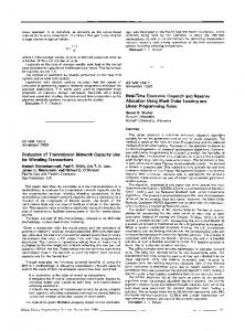
The increases of operating frequency and the die size projection to 2.4x2.4cm2 for CMOS circuits have led to the investigation of wireless interconnection within and between IC’s. Use of on-chip antennas as an alternative interconnect for clock distribution (Fig. 1) is being investigated [lj-[5] to reduce skew and alleviate the dispersion problem. On-chip antennas could also be used in communication links for sensor networks, radio frequency identifiers (WID’S), and a single chip radar. An on-chip antenna has been used as a near field coupler in an RFID. This completely eliminates the off-chip bond wire connections thus, radically improving the ease of use and reliability, and lowering packaging cost [ 5 ] . In all these applications, on-chip antennas are co-located with circuits and the associated interconnects such as a power grid, clock trees, and data lines. A serious concern for this is that the metal structures will significantly affect the on-chip antenna characteristics, such as gain, phase, and antenna input impedance [6]. Approaches to better guarantee the characteristics of on-chip antennas are critical to provide predictability for the design community. This paper reports that adding metal structures near an on-chip antenna in the presence of a power grid has greatly reduced impact on antenna characteristics. Exploiting this, a set of design rules for antenna layout has been proposed and presented in this paper.
Fig 1. Intra-chip clock distribution system.
Antenna simulations The Finite Difference Time Domain Method(FDTD) and Finite Element Method(FEM) have been used for evaluation of a power grid [7] and interference structures for on-chip antennas Ex]. In order to validate the simulation results, a set of representative test structures consisting of 2-mm long linear dipole antenna pairs and varying interference structures have been simulated using HFSS and compared with the measurement results. This work is supported by SRC (Task ID: SS5.001)
120
Local Clock Trees
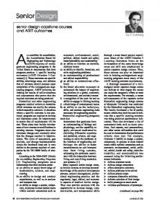
The test structures were fabricated using the UF three metal layer process on 20-R-cm silicon substrates. The metal layers were separated using PECVD SiOz layers. Fig. 2(a) shows a structure which has been both simulated and measured. Two 2-mm long linear dipole antennas are separated by 5 mm. The interference structure consists of two 3-mm long and 100-pm wide bars which run parallel to the antennas. The spacing to antenna is 50pm. Figs. 2(b) and (c) show the simulated and measured ISI21for the antenna pairs without and with the interference structure shown in Fig. 2(a). Between 22 and 26 GHz, the presence of interference structure lowers lS121 between the antenna pair by 20 dB. The simulations are in within 3-4 dB of the measurements especially at frequencies higher than 24. Having verified reasonable correspondence between the measurement and simulation results, 3-D EM simulations are used to more rapidly evaluate the impact of a wide variety of interference structures. In particular, the design rules for antenna layout have been developed for a back-end process with 5 metal layers of A1 separated by Si02 layers. The substrate resistivity is 20 Q-cm. An aluminum metal plate is used in the back side of silicon substrate to represent a heat sink. The perfectly matched layer (PML) is used for radiation boundary. The power grid is formed using metal 5, data lines are formed in metal 2-4 layers in Fig. 3. Input impedance, and magnitude and phase of S,, for antenna pairs (5-mm separation) are simulated at varying separations between the power grid and antenna at 24GHz. Fig 4 indicates that lS121(dB) linearly depends on D l and D2 shown in the Fig. 3. The power grid has significant effects on the characteristics of on-chip antennas.Compared to the control case, ISl2[is reduced by -20 dB. This is due to the destructive interference effects of reflected waves from the power grid.
-
0-7803-8752-W05/$20.0002005 iEEE
ANT INF
-60
INF ANT
t
1 I
-8s:
23
24
25
26
Frequency(GHz)
IC-Slmulation
-c Measurement -20
- 9 2
23
24
25
Frequency(GHz)
26
Fig 2. Comparison of simulation with measurement data for antenna pairs with 5-mm separation. (a) A simulated and measured structure, (b) IS121 (dB) of the control structure (without interference structures), and (c) ISl2!(dB) of the interference structure.
This is indeed a significant reduction. However, much of this can be recovered by using an AIN propagating layer in conjunction with antennas on thinned substrates. It has been shown recently that the gain can be improved by 10, 15 and 20dB for 0.5, 1 and 2-cm antenna pair separations [9] over the best previously reported results [lo]. The cause for input impedance change is the near field coupling between the antenna and power grid. The separation D 1 has more significant effects on the antenna performance than D2. lSL21(dE3) is .
Air
Metal 5 Metal 4 Metal 3 Metal 2 Metalil - Silicon - Metal
t
-35
I
300
350
4w
I 450
WPm)
Fig 4. (a) S12(dB), (b) Phase (C) real part of input impedance, and (d) imaginary of input impedance of an antenna pair (5-mmseparation) versus distance D1 and D2. The blue line is simulated data and black line is curved fitted lines at 24GHz
Oh
- \
Atdenna (Metal 1) Power Grid (Mletal 5)
Fig 3 . A cross section and a planar view of a power grid with an onchip antenna.
degraded k0.37 dBi5Opm. The phase does not change much with the variations of D1 and D2. The linear dependency of input impedance is about f 1R/50pm. These indicate that the dependences of lSl&clEi), phase, real and imaginary part of impedance can be expressedas linear combinations of Dl and D2 in conjunction with a constant as given below. These equa-
121
tions can be used during the layout of antennas and power grid, D, and D2 are in pm. IS,,/(dE) = 7 . 4 10-3xD2-69.2+ ~ 1 . 6 7 ~IO-*xDl Phase = 2 x IO-* X D + ~ 33.941 - 1.3x IO-*
X D ~
R e a l ( Z I 1 )= 1 . 7 ~ 1 O - ~ x D 2 + 3 5 . 4 8 + 1 . 7 7 x l O - ~ x D l -3 I m ( Z 1 , ) = - 2 x 10 x 0 2 - 4 0 . 3 7 + 3 . 0 6 x 1O-*XD1
When the polarization of the incident wave is parallel to a densely packed wire grid, the reflection coefficient for the wire grid is almost equal to -1. The power grid acts like a metal plate reflecting incident waves (Fig. 5 ) , so data lines, the local clock trees, and dummy fills have relatively small effects on the antenna performance. The simulation structures and results are shown in Fig. 6. The simulation results are listed in Table 1.
ence of a power grid reduces lS121, however it makes the antenna characteristics to be almost independent of other metal structures. This allows definition of a relatively simple sei of design rules for on-chip antennas. Table 2 lists the design rules when followed should make on-chip antenna characteristics more predictable. power lines directly over antenna should be avoided in region A. D1 and 02 are 255 pim and 275
I
2
I Any metal structures can be placed in region E. Perpendicular metal lines to antenna off by 200 pm away are acceptable (Fig 6.(b)). To run multiple perpendicular metal lines over antennas, the characteristicsof antennas must be simulated using an E-M software.
3 4
5
I
6 7
Short (lengthcl OOpm, width20pm) discontinuous metal lines are acceptable in the region A. These lines can be connected to transistors.
I
I I
Local clock trees can be olaced over the area A and B.
Dummy fills (size:lOpmxlOFm and space>lOpm) are acceptable in regions A and B
Table 2. Design rules.
Conclusions Fig 5. Conceptual division of the chip area. A: an antenna. B: an area under the power grid,
area near the
1 1 1 1
I 1
1 1 . ,
Fig 6. (a) Antenna with apower grid, (b) antenna with a power grid and local clock trees, (c) antenna with a power grid and data lines,
and (d) antenna with a power grid and dummy fills.
., id)
,
I
I
40.5
I
I
I
-26
I
-60.2
I
27
Tablel. Simulation results of antenna pairs at 24GHz in the presence of interference structures shown in Fig. 6.
For the wireless clock distribution system, because the transmitted clock is frequency divided by S, phase variations of 1% of a period or skew for the actual clock correspond to 28 degrees for the transmitted clock signal. One percent is onetenth of the typical skew/jitter tolerance and this can be used as the criterion to determine acceptability of variations. Based on this, all the structures in Table 1 are acceptable. The pres-
122
The impact of realistic metal interference structures which can significantly modify the characteristics of on-chip antennas, such as a power grid, local clock trees and data lines have been investigated primarily using EM simulations. In the presence of a power grid, the antenna pair ISlz[can be traded off for improved stability of antennas characteristics. This can be exploited to define a set of design rules to improve the predictability of on-chip antenna characteristics in the presence of other metal structures. References [ I ] K. 0,et al., “Inter and h a - c h i p Wireless Clock Signal Distribution Using Microwaves: A Status of an Initial Feasibility Study”, GOMAC, pp 306-309, Monterey, CA, 1999. [ 2 ] K. Kim and K. 0, “Integrated Dipole Antennas on Silicon Substrates for Intra-chip Communication,” LEEE AP-S Intl. Symp., pp 1582-1585, Orlando, FL, 1999. [3] K. Kim and K. K.0, “Characteristics of Integrated Dipole Antennas on Bulk, SO[, and SOS Substrates for Wireless Communication,” Proceedings of the IITC, pp 21-23, San Francisco, CA, 1998. [4] K. Kim, H. Yoon and K. 0, “On-Chip Wireless Interconnection with Inregrated Antennas”, IEDM Technical Digest, pp. 485-488, San Francisco, CA, 2000. [5] K. K. 0 et al., “Wireless Communications Using Integrated Antennas,” in Proc. Intl. Interconnect Tech. Conf., San Francisco, CA, June 2003, pp. 111113.
[6] X. Guo, R. Li, and K. K. 0 “Design guidelines for reducing the impact of metal interference stmctures on the performance on-chip antennas,” IEEE APS Intl. Symp., pp22-27, June, 2003. [7] 1. Choi, L. Wan, S . M, B. 6, M. R, ”Modeling of realistic on-chip power grid using the FDTD method” IEEE, EMC Intl. Symp., VoI.1, pp238-243, 2002 [S] A. E.M. Harum-ur Rashid, S. Watanabe, T.W a w a , X.Guo, and K. K. 0, “Interference Suppression of Wireless Interconnection in Si Integrated Antenna,” 2002 IITC, pp. 173-175, San Francisco, CA, 2002. [93 X. Guo, R. Li, and K. K. 0,To be published. [ 101 X.Guo, et al., “Propagation Layers for intraChip Wireless Interconnection Compatible with Packaging and Heat Removal,” Dig. of Tech. Papers, 2002 Symp. on VLSI Technology, pp. 36-37, Honolulu, HI, June, 2002.