The RIKEN Superconducting Ring Cyclotrons (SRC-. 4 and SRC-6) are one of the main accelerators of the ". RIKEN RI Beam Factory" [1] . Six units of.
Design Study of Sector Magnet for the RIKEN Superconducting Ring Cyclotron (2) Takeo Kawaguchi, Toshiyuki Kubo, Toshinori Mitsumoto, Toshiharu Tominaka, Siro Fujishima, Hiroki Okuno, Yasushi Tanaka, Jong-Won Kim, Kumio Ikegami, Akira Goto, and Yasushige Yano The Institute of Physical & Chemical Research (RIKEN), Hirosawa 2-1, Wako-shi, Saitama, 351-01, Japan
Abstract A conceptual design of the superconducting sector magnet for the RIKEN's future superconducting ring cyclotron is described. A structure, magnetic forces, superconducting coils and a cryogenic system are discussed. Special features are: the cold pole arrangement, the supporting structure for huge magnetic forces and the cryogenic stable coils.
1 INTRODUCTION The RIKEN Superconducting Ring Cyclotrons (SRC4 and SRC-6) are one of the main accelerators of the " RIKEN RI Beam Factory" [1] . Six units of superconducting sector magnets are used as the main components of SRC-6. Each of sector magnets must generate a maximum magnetic field of 4.5T in the beam orbital area. We use superconducting main coils and also superconducting trim coils to obtain compactness in size and to save electric power and cooling water. The yoke and pole made of magnetic soft iron are arranged in the sector magnet to reduce ampere turns of the superconducting coils and to minimize the leakage magnetic flux. Table 1 shows the main parameters of the sector magnets.
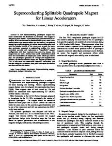
2 STRUCTURES OF SUPERCONDUCTING SECTOR MAGNET Figure 1 shows the section of the sector magnet. Main components of the magnetic elements are superconducting and normal conducting coils, poles and a yoke. We use two kinds of superconducting coils: a pair of main coils and a group of trim coils. Both coils are located upper and lower sides with respect to the mid plane. A group of normal conducting trim coil are also arranged in the upper and lower side of the beam chamber, to obtain a strictness of isochronous fields. A special feature is the cold pole arrangement. This arrangement gives a mechanical support against the huge magnetic force of the main coils, and gives a decrease of the magnetic force as well as an ampere-turns, compared with a warm pole arrangement. A vertical magnetic force Fz over 1500 tons is supported with two coil-links which are located in between the upper and lower cold poles. We are investigating two ways of supporting a magnetic shifting force Fx of over 300 tons in radial direction. One way is to arrange a pair of cold rings which connect
the cold masses (coils and cold poles) of the six sector magnets in 4.5 K region. This cold ring support is shown in Fig. 1. A problem of the cold ring support is the central space for the cyclotron. This space is limited to arrange the beam injection elements. Another way is to use large size thermal insulated supports made of high strength material like as Titanium alloy, in between the cold mass and the yoke, using the outer space of the sector magnet. The problems of this thermal insulating support are its large heat leak, and its mechanical deflection which causes a position shift of the field. Table 1 Parameters of sector magnet. Average Radii of beam injection, 3.56m, extraction. 5.36 m. Sector Angle of main coil 25 degree Maximum Magnetic Fields in beam orbital area, 4.5 T, in Main coil, 5.5 T, in Trim coil 5.0 T. Main Coil Ampere Turns per Magnet 6.0 MA Coil Cooling Method LHe bath cooling Magnetic Stored Energy of 6 Magnets . 450 MJ ( 75 % in Air, 17 % in Cold Poles, 8 % in Yokes) Maximum Operation Currents for Main Coil , 5000 A, for Trim Coil. 500 A. Iron Weights of 6 Magnets Cold Poles, 216 tons, Yokes. 3630tons.
3 MAGNETIC FORCES Table 2 shows the calculated magnetic forces of the main coil and the cold pole with an ampere turns of 6 MA per magnet ( per two coils). The vertical force Fz of 1520 tons is supported with two coil-links, and makes a bending deflection of 3 mm for the cold pole of 445 mm thickness. The shifting force Fx of 340 tons must be maintained with the cold ring or the thermal insulating supports. This shifting force is produced by the arrangement of six sector coils and the asymmetry configuration of the coils and the irons.
4
SUPERCONDUCTING COILS
The main superconducting coil has triangle shape with two long straight sections of about 3.5 m long.
The magnetic force on the main coil is supported by the coil vessel and the cold pole. We apply a cryogenic stabilizing method for the main coil and the trim coil to prevent coil quench. The average current density of them should be less than 40 A/mm2 and 50 A/mm2, respectively. The specifications of the superconducting wires are shown on Table 3. The copper stabilizer of the main coil conductor will be treated to have rough surface of 0.25mm depth, and also treated with oxidization for increasing a heat flux. For the stabilizer of the trim coil conductor, 4 - nine pure aluminum is applied having no surface treatment. There is a possibility to use 4 - nine aluminum stabilizer instead of copper stabilizer for main coil conductor comparing the mechanical properties, the magnetic resistivity, the temperature rise at coil quench and the price.
360 tons, and it will take one month to cool from room temperature to 4.5 K. The cold mass will be kept in low temperature as long as possible. When one refrigerator breaks down, the magnets can be kept at 5 to 6 K with the other refrigerator. We have one or two days of power off a year for power system maintenance, and at that time a recovery compressor with an emergency power source will recover the evaporated helium gas to the buffer tank. We have no liquid nitrogen in this cryogenic system.
6
A design study of the superconducting sector magnet for RIKEN superconducting ring cyclotron has been carried out. The structure, the magnets forces, the superconducting coils, and the cryogenic system has been discussed. We are going to construct a model superconducting sector magnet to verify our design.
5 CRYOGENIC SYSYTEM Two refrigerators having a capacity of 500 W each at 4.5 K will be used for the six sector magnets and the beam injection / extraction magnets. Figure 2 shows the cooling diagram. We expect to operate the superconducting ring cyclotron for more than 6000 hours a year. The cold mass weight of the six sector magnets is
Table 2 Magnetic forces of main coil and cold pole unit: ton for a Half Coil Fx Fy Fz No. 1 element -113 0 -67 No. 2 -162 137 -89 No. 3 -180 922 -304 No. 4 170 214 -71 No. 5 345 23 -106 Sum. 60 1296 -637 for a Cold Pole 51 0 -249 for A Half Cold Mass 171 0 -1523 ( One main coil and One Cold Pole) for A Magnet 342 0 0 ( One Cold Mass)
CONCLUSION
REFERENCE 1) Y. Yano et al. : ' Progress of RIKEN RI Beam Factory Project ' , These proceedings.
No.4 No.3 No.2
y
No.5
x z
No.1
Table 3 Specifications of superconductor. [Main Coil ] [Trim Coil ] 5000 500 12000 at 6 T 1200 at 6 T more than 6000 more than 600 ( Maddock Type) (Stekley Type) Outer Dimensions (mm) 7.5 X 14 2.3 X 2.8 Material Cu / Cu - NbTi Al / Cu - NbTi Stabilizer / SC 12.7 / 1.1 / 1 7.3 / 1.1 / 1 Surface treatment 0.25 mm rough surface and Oxidization Non Total Length for6 Magnets 77 km 47 km Max. Operation Current (A) Critical Current (A) at 4.3 K Cryogenic Stabilizing Current (A)
THERMAL INSULATING SUPPORT
YOKE
TRIM COIL (super) MAIN COIL COLD RING TRIM COIL (normal)
5.4 m MID PLANE
MICÅ@ COIL LINK
BEAM CHAMBER
CRYOSTAT 80K SHIELD
10 m
0
Fig. 1. Construction of superconducting sector magnet.
RECOVERY COMPRESSOR
SAFETY VALVE
GHe BUFFER TANK 10-15 ata
RUPTURE DISK POWER LEAD GHe
TRANSFER TUBES MAIN COMPRESSOR
LHe TANK
6 SECTOR MAGNETS & BEAM CHANNEL MAGNETS
LHe BUFFER TANK
COLD BOX
Fig. 2. Cooling diagram for 6 secter magnets and beam channel magnets