Design, system integration and control concepts of an adaptive active vibration absorber for a convertible J. Millitzer1, T. Ehrt2, A. Plückhahn3, P. Knauer3 1 Fraunhofer Institute for Structural Durability and System Reliability LBF Bartningstr. 47, 64289 Darmstadt, Germany e-mail:
[email protected] 2
Vibracoustic GmbH & Co. KG Höhnerweg 2-4, 69465 Weinheim, Germany 3
Audi AG 85045 Ingolstadt, Germany
Abstract As convertible cars have a relatively flat geometry, they are prone to torsional vibrations. The conventional way to suppress such vibrations is to install passive linear absorbers in the rear of the car. However, these passive absorbers add up to 25 kg to the weight of the car. Furthermore their effectiveness is reduced by all effects which change the weight or the stiffness of the car such as baggage, temperature or aging effects. In order to overcome these drawbacks, an active linear absorber for convertibles has been developed. It has been designed to fit into the same space as the existing passive system, yet reduces the weight by about a factor of 2. Furthermore the performance of the system has been significantly increased, which was evaluated during a harmonic torsion analysis, as well as during driving tests under bad road conditions. By means of an adaptive control algorithm the system adapts to varying stochastic excitation and to changes of the car’s structural properties.
1
State of the art & tasks of development
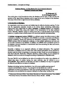
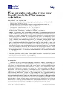
The torsional stiffness of the car body is a significant factor for the vibrational comfort of automobiles. In conventional cars with closed roof the torsional resonance is tuned to a frequency range between 28 Hz and 32 Hz. In this frequency band the external excitation by the road surface and internal excitation by the engine or any vibratory system of the car is marginal for ride comfort. Because of the missing roof, convertible cars have the drawback of a low torsional frequency ft. In Figure 1 the typical mode of the first torsional eigenfrequency is shown. Due to the proximity to the resonance frequency of the axes fa≈ 15 Hz this torsional mode is highly excited (Figure 2). Thus, it’s an essential aim during the development of a convertible car to raise the torsional frequency by measures like struts in the underfloor or the front part of the car. Furthermore structural reinforcements of highly tensioned parts of the car body, especially the sills are applied to reach stiffness gains. Despite all these efforts the torsional frequency usually doesn’t exceed a value of approx. 18 to 20 Hz in the B- or C-class segment of convertible cars, respectively approx. 22 to 24 Hz in small and sportive cabriolet.
331
332
P ROCEEDINGS OF ISMA2012-USD2012
Figure 1: Torsional eigenmode of a car body To reach an adequate comfort level, secondary measures are often inevitable. By the application of passive vibration absorbers mounted at one or more corners of the car body, it’s torsional movements can be effectively reduced (see also Figure 4 in chapter 2.1 „Proposed rules of design for an active vibration absorber”). Such an absorber consists of a mass mounted on two or more elastic elements, all embedded in a framework. There are several drawbacks of this technology. First of all these absorbers add an extra weight of up to 25 kg to the car body. Together with the numerous stiffening measures mentioned above this enhances the overall weight of a convertible car even more. The test object, an AUDI A5 cabriolet, is equipped with a tuned mass damper of approx. 13 kg at the front right longitudinal member (Figure 3). In order to achieve the maximum effect of the absorbers they are developed to function in a narrow frequency band where the operational vibration of the car body reaches its maximum. The frequency of this maximum fmax varies due to different suspension settings or different engine-gearbox combinations. Because of non-linearities also the amplitude level of the road excitation has an essential effect to the location of fmax. Furthermore the hardly predictable influences of deterioration, temperature and humidity especially on the elastic elements of the absorber should also be mentioned. Therefore the design of a passive vibration absorber is always a compromise between function and costs.
excitation
amplitude
resultant vibration
Amax(ft)
0
10
fa 20 frequency [Hz]
ft
35
maximum amplitude Amax
car body (torsion) Amax
15
20 25 30 torsional resonance of the car body ft [Hz]
Figure 2: Interaction between torsional resonance of the car body of a conventional car and the excitation of the unsprung masses (left); Dependency of the maximum amplitude close to excitation resonance Amax on the torsional resonance of the car body ft (fa 15Hz) (right)
ACTIVE NOISE AND VIBRATION CONTROL
333
Figure 3: Position of the mass damper in an AUDI A5 cabriolet A passive vibration absorber is a highly challenging component during the development of a convertible car. Despite all their disadvantages such absorbers are still the current state of technology to reduce torsional vibrations in a frequency range of 16 Hz to 20 Hz. Especially because of rising expectations of the customers as well as rising importance of light weight construction, the conventional measures to raise the comfort level in a convertible car are neither sufficient nor appropriate any more. The primary objective of the present investigation is to develop an active system which can replace the passive mass damper meeting the following requirements: increased reduction of the acceleration level at certain comfort points in comparison to the passive component, which is measureable and clearly detectable in subjective perception significant reduction of weight in comparison to the passive mass damper adaptive to different operation conditions (variable excitation levels respectively variable structural properties) applicable in the available space of the existing car These requirements are countered with an active vibration absorber as shown in the following chapters.
2
Design of an active vibration absorber
In order to reduce torsional resonant vibrations, a tuned mass damper can be mounted to the car’s chassis, reducing the amplitude of mechanical vibrations. However, in order to attain design rules for an active vibration absorber, a simplified coupled mass-spring-damper system according to Figure 4 (right) is implemented. Having no actuator force, the upper mass-spring-damper system can be designed as a tuned mass damper, following the design rules introduced by Den Hartog [1]. For a given mass ratio μ=m2/m1 the frequency ratio ν and the optimal modal damping ξ2opt can be calculated according to Equation 1.
1
2 1
1
and
opt 2
3 8(1
)
(1)
The stiffness ki and the damping constant ci of the mass-spring-damper can easily be calculated by means of the well-known equations: i
ki and mi
i
ci 2m i
.
(2)
i
For a performance estimation, the natural frequency of the lower mass-spring-damper system is chosen to f1=20 Hz, with a quite large modal damping of ξ1=30 % and a mass of 150 kg. Latter variables and a simplified system topology are chosen to evaluate the fundamental system behavior and the design rules
334
P ROCEEDINGS OF ISMA2012-USD2012
for an active vibration absorber in general. However, by attaching a tuned mass damper designed by means of the previously introduced equations and a mass of m2=16 kg the resonant vibrations are reduced. Figure 4 (left) shows the influence of the attached tuned mass damper compared to the system behavior without any additional system. Whereas the calculated natural frequency of the tuned mass damper is f2=18 Hz and a modal damping of ξ2opt=19 %. A band-limited white noise force Fext was used to excite the system.
2.1
Proposed rules of design for an active vibration absorber -80
system admittance [dB(m/s/N)]
original system
m2
tuned mass damper active vibration absorber
k2
Factuator
c2
. Fext x1
-85
m1 increased performance
-90 10
15
20
25 30 frequency [Hz]
k1
35
40
Wopt(z)
c1
45
Figure 4: Resulting admittance of the lower mass m1 (left) and system topology (right) Inducing additional active forces (Figure 4, right), e.g. by means of a current-controlled moving-coil actuator, the vibration level can be lowered once more, requiring no additional mass. In order to compare different settings for the natural frequency and the modal damping of the tuned mass damper with an additional active force, i.e. the active vibration absorber, an ideal force actuator is used. Furthermore neither dynamic behavior of the sensor nor dynamic behavior of the power amplifier is taken into account. A further description of inertial mass actuators and their electrical system description can be found in [2]. For a numerical investigation, the active vibration absorber is controlled by means of a broadband feedforward control algorithm, in brief, the Filtered-Reference-Least-Mean-Squares (FxLMS) algorithm. The band-limited white noise excitation force Fext is used to calculate an optimal actuator signal Factuator, whereas the control filter Wopt(z) is adapted in such a way that the velocity of the lower mass is minimized by means of a gradient based adaptation algorithm. For a detailed description of the implemented feedforward control algorithm the reader is referred to [3]. In order to compare different settings for the natural frequency and modal damping of the active vibration absorber, the absorber’s mass m2 and the induced active force, in brief its rms-value, is held constant. By means of the design rules for a tuned mass damper system, the natural frequency and the modal damping for a passive system can be calculated, which serves as a base for the estimation of the optimal values of an active vibration absorber. In a first step, the modal damping is held constant and the natural frequency and hence the stiffness k2 is lowered (as m2 is constant). As a result, the optimal natural frequency is generally lower than the natural frequency that is suitable for a passive tuned mass damper system. Furthermore the optimal natural frequency of the active vibration absorber depends on the available actuator performance as a higher actuator performance leads to a lower suitable natural frequency. Figure 5 shows the remaining vibration level for different values of the natural frequency of the active vibration absorber with different actuator settings (left). In case of an actuator with low performance the optimal natural frequency f2=16.5 Hz differs slightly from the natural frequency of the passive system (f2=18 Hz). Increasing the actuator performance by a factor of 2.5, leads to a significant derivation of the optimal natural frequency (f2=12.4 Hz) of the active vibration absorber. For this reason, the available actuator performance should be taken into account, concerning the optimal design of the active vibration absorber.
ACTIVE NOISE AND VIBRATION CONTROL
335
Regarding the different performance settings examined, the actuator requires 6 %, 11 % and 15 % of the induced excitation force as actuator force. The optimal modal damping constant slightly differs from the one calculated by means of the design rules for a tuned mass damper (ξ2opt=19 %). Figure 5 (right) shows the optimal modal damping constant and the mean remaining vibration level for different actuator settings with an optimal natural frequency calculated by means of the previously mentioned method.
-85.5
remaining mean vibration level [dB(m/s/N)]
remaining mean vibration level [dB(m/s/N)]
For a further analysis, the numerical model ought to be extended, based on a detailed numerical model of the cars chassis, an excitation model, an improved model of the active vibration absorber that includes the electrical mechanical coupling, the dynamic behavior of the sensor and the power amplifier, the latency, the sampling time of the signal processing unit and so on, which leads to a holistic simulation procedure for smart structures e.g. introduced in [4]. It should be noted that this design procedure is suitable for a passive measure as well.
-86 increased performance
-86.5
-87 10
12
14 16 natural frequency [Hz]
18
-85.5
-86
increased performance
-86.5
-87 0
10
20
30 40 50 modal damping [%]
60
70
Figure 5: Remaining vibration level for a variation of the natural frequency of the active vibration absorber (left) and the modal damping (right) with increased actuator performance. The circle highlights the attainable minimum.
2.2
Active linear absorber prototype
In order to produce the same level of forces with an active vibration absorber of lower weight, one has to raise the free travel in the same ratio as the mass is reduced. This leads to some challenges with respect to the linear guiding of the mass as a linear spring characteristic is desired over the full damper travel. In addition, a small air gap for the coil is required in the magnetic field; this also calls for good linear guiding.
leaf springs moving mass
transition spacer power electronics
Figure 6: Active linear absorber prototype
336
P ROCEEDINGS OF ISMA2012-USD2012
The Vibracoustic design introduces four packs of leaf springs for linear guiding. The first outer pair connects the stator to a transition spacer piece. A second inner pair of springs connects this transition piece to the moving mass itself. The transition spacer covers half of the working travel and all of the lateral travel, providing perfect linear guiding for the damper mass. The damper mass includes the pair of permanent magnets and the steel parts necessary for the magnetic field in which the stator coil operates. The free space between damper mass and transition spacer which is governed by the desired spring rate, leading to a certain spring length, is filled with the power electronics. This reduces the cable length for the high current supply to the coil. The active vibration absorber replaces the passive vibration absorber whose mounting position can be obtained from Figure 3 and whose working direction is along the vertical axis of the car.
3
Control concepts
Regarding the control of the active vibration absorber, several concepts were taken into account, concerning both, closed loop concepts as well as control concepts based on adaptive digital filters. In the latter case, as it is difficult to obtain a suitable measurable reference signal, an adaptive feedback control topology was investigated and satisfies the requirement to adapt to variable excitation levels respectively variable structural properties. However, due to the mounting position and the given direction of action of the active vibration absorber a reduction of the vibration level at the mounting point of the active vibration absorber doesn’t cause an optimal performance concerning the reduction of the vibration level at the distributed comfort points which was verified during both, a harmonic torsion analysis, as well as driving tests under actual road conditions. Therefore, closed loop concepts that are based on the feedback of collocated state variables, e.g. the acceleration at the mounting point, are not presented within this paper. For a further description of closed loop control concepts the reader is referred to [5].
3.1
Adaptive Feedback Control
Wopt(z) ^ S(z)
x‘(n)
y(n)
S(z)
y‘(n)
d(n) +
e(n)
LMS ^ S(z) ^ d(n)= x(n)
^ y‘(n)
+
+
Figure 7: Internal model control FxLMS Figure 7 shows the finally applied internal model control (IMC) Filtered-Reference-Least-Mean-Squares (FxLMS) algorithm, which is basically an adaptive feed-forward system that synthesizes its own reference signal x(n) using the available actuator control signal y(n) and the measured error signal e(n). This technique was introduced by Erikson [6] and a further description can be found in [3] and [7]. The actuator control signal y(n) is computed by means of a reference signal x(n) which is fed forward through an adaptive control filter Wopt(z) with L filter coefficients. L 1
y ( n)
wl (n) x(n l )
(3)
l 0
The general aim of the algorithm is the minimization of the instantaneous error signal e(n), which equals the measured comfort point acceleration and is the superposition of the disturbance signal d(n) and the
ACTIVE NOISE AND VIBRATION CONTROL
337
output of the control path S(z). The implemented LMS algorithm updates the control filter Wopt(z) by means of a gradient estimation which points in the direction of the minimum of the error surface E{e(n)²}.
wl (n 1)
wl (n)
x (n l )e(n)
l
0 ,1,, L 1
(4)
The adaptation step size µ can be normalized with regard to the filtered reference signal’s power, leading to an optimized speed of convergence [3]. The filtered reference signal is calculated from the regenerated reference signal x(n) and an impulse response estimation of the control path S(z) with M filter coefficients computed using a system identification with an adaptive digital finite impulse response (FIR) filter [8]. M 1
x ( n)
sˆm x(n l )
(5)
m 0
The estimated transfer function Ŝ(z) includes all, the D/A and A/D converter, the antialiasing and reconstruction filter, the actuator’s and sensor’s dynamic behavior, the power amplifier, the electrical mechanical coupling as well as the mechanical system. As previously mentioned, the IMC FxLMS algorithm synthesizes its own reference signal by means of the available measured acceleration e(n) and the actuator control signal y(n). For a computation of the reference signal x(n), the actuator control signal has to be filtered as well, leading to a higher computational effort compared to a purely feed-forward control algorithm.
x ( n)
dˆ (n)
M 1
e(n)
sˆm y(n m)
(6)
m 0
A great advantage using the internal model control FxLMS is that the algorithm does not require a collocated actuator sensor positioning, thus even distributed comfort point accelerations can be measured and serve as a target for vibration suppression. Furthermore the control algorithm takes the dynamic behavior of the control path into account, simplifying the control design. Concerning modeling errors of the estimated control path transfer function Ŝ(z) the algorithm remains stable to a certain extend [3]. However, regarding a time-variant behavior, the control system might be expanded to the above-presented control algorithm with additional online system identification, which leads to a trade-off between vibration suppression and tracking performance. In order to reduce the vibration level at different comfort points at the same time with only one actuator, several single-input-single-output controllers with shared actuator performance can be applied. For a further investigation of a distributed control scenario the reader is referred to [9].
4
Numerical investigations
For a numerical investigation, the simulation model has to contain both, a numerical system description of the control path as well as a realistic excitation. The latter is the measured acceleration at several distributed points at the cars chassis, containing for example the mounting point of the active vibration absorber, the steering wheel, the A-pillar and the driver’s seat. The numerical system description, in brief a time discrete state space representation S*(z) with reduced order, is estimated from the measured data of a sweep excitation of the active vibration absorber’s current and the related measured acceleration at the previously mentioned distributed comfort points. Figure 8 shows the topology of the simulation model and the applied control algorithm in a single-input-single-output control scenario, whereas a different sensor position can be chosen by means of a channel selection, leading to different targets concerning the reduction of vibration.
338
P ROCEEDINGS OF ISMA2012-USD2012
measured acceleration
Wopt(z) ^ S(z)
x‘(n)
y(n)
S*(z)
y‘(n)
d(n) + 22
e(n)
LMS ^ S(z)
remaining acceleration
-
^ y‘(n)
channel selection
+
+
^ d(n)= x(n)
Figure 8: Applied simulation model with implemented IMC FxLMS In order to verify the functionality and to attain a first performance estimation of the controlled system behavior, the A-pillar’s sensor in transverse direction serves as a target for vibration suppression by means of the active measure. With a given mounting point of the active vibration absorber at the passenger’s side of the chassis’ front in vertical direction, both the behavior of the (controlled) error sensor at the A-pillar in transverse direction as well as the behavior of other measuring points was evaluated against the behavior with the serial passive absorber. As is apparent from Figure 9, the torsional mode at 18 Hz is responsible for an increased vibration at the A-pillar in transverse direction (left) whereas implementing the adaptive active vibration absorber, leads to a significant reduction of torsional mode induced acceleration components at the A-pillar in transverse direction. The available actuator performance is limited to the maximum peak-current of ±10 A. Additionally a reduction of the torsional vibration component at the A-pillar in transverse direction is not necessarily coherent to a reduction of the vibration at the mounting point of the active vibration absorber, depending on both its working direction as well as its actual mounting position. Thus, control strategies that aim for a reduction of the mounting point accelerations, might have poor performance concerning the reduction of torsional mode vibrations at the A-pillar in transverse direction for the given actuator position and its working direction. Concerning the behavior of other relevant comfort points, e.g. the acceleration at the steering wheel in transverse direction is also minimized on the same scale, whereas the acceleration at the driver’s seat and the passenger’s seat increases slightly. A similar behavior was observed during the driving test under bad road conditions, presented in following section. mounting point vertical direction
serial passiv absorber active vibration absorber
acceleration [dB normalized]
acceleration [dB normalized]
A-pillar transverse direction
0
-10
-20 10
15
20 frequency [Hz]
25
30
serial passiv absorber active vibration absorber 0
-10
-20 10
15
20 frequency [Hz]
25
Figure 9: Acceleration with and without the active measure (simulation results)
30
ACTIVE NOISE AND VIBRATION CONTROL
5
339
Experimental investigations
The basic setups were developed on a hydraulic four poster test rig during a harmonic torsion analysis. An artificial harmonic torsion signal was used for excitation, moving to the next frequency after steady-state oscillation was measured. For comparison, the vehicle was measured without any mass damper and with the series passive mass damper which is the reference for all evaluations. As the test procedure holds each frequency until steady-state oscillation is obtained, this represents a major advantage for the algorithm: The time to adapt the control filter Wopt(z) is relatively large and complete actuator performance is available for a single frequency component. In a first test, the acceleration at the A-pillar in transverse direction serves as a target for vibration suppression by means of the active measure. As a result, Figure 10 shows that a significant improvement is achieved by the A-pillar controlled active vibration absorber. On the other hand, this control concept leads to higher vibrations on the seat rail in vertical direction. The opposite behavior is observable for the subsequently investigated control concept, which uses the seat rail accelerations in vertical direction as a target for vibration suppression. A combined control algorithm, which takes A-pillar and seat rail acceleration into account, leads to a compromise concerning the reduction of vibration at the A-pillar and the driver’s seat at the same time. The results achieved with this concept are shown advantage to the controlled active vibration absorber, it was not to be expected that this setup would perform satisfactorily in road measurements or subjective rating, which turned out to be the case. acceleration [dB normalized]
0
without mass damper -10 passive mass damper A-pillar controlled mass damper -20
Seat rail controlled mass damper A-pillar and seat rail controlled
-30
10
20 frequency [Hz]
30
acceleration [dB normalized]
Figure 10: Vibration level A-pillar, test rig results in five different setups
0 without mass damper passive mass damper
-10
A-pillar controlled mass damper -20
Seat rail controlled mass damper A-pillar and seat rail controlled
-30 10
20 frequency [Hz]
30
Figure 11: Vibration level seat rail, test rig results in five different setups
340
P ROCEEDINGS OF ISMA2012-USD2012
5.1
Driving tests
acceleration [dB normalized]
After the basic setup was evaluated on the test bench and before the final subjective rating by professional test drivers, objective evaluations were carried out on a nearby uneven road for stochastic excitation of the car. The car was driven at constant speed; the speed selected had been determined by the test drivers as exciting the torsional mode effectively during an earlier stage. Again three active setups were driven in addition to the two setups without mass damper and series passive mass damper. Measurements were made at all comfort points and several structural points. Figure 12 and Figure 13 show the vibration level at two comfort points, A-pillar in transvers direction (top) and seat rail in vertical direction (bottom), in five different setups.
without mass damper 0 passive mass damper A-pillar controlled mass damper -10
Seat rail controlled mass damper A-pillar and seat rail controlled
-20 10
15
20
25
frequency [Hz]
acceleration [dB normalized]
Figure 12: Acceleration level A-pillar, driving test results in five different setups 0 without mass damper passive mass damper -10
A-pillar controlled mass damper Seat rail controlled mass damper
-20
A-pillar and seat rail controlled 10
15
20
25
frequency [Hz]
Figure 13: Acceleration level driver’s seat, driving test results in five different setups It can be seen clearly that the passive mass damper brings considerable benefits in terms of A-pillar vibration at about 18 Hz. This benefit is almost doubled by the active mass damper operated in A-pillar controlled mode. The seat rail controlled mass damper shows approximately the same benefit as the passive damper on the A-pillar with some additional benefit on the seat rail at about 15 Hz but drawbacks at about 20 Hz in the same position. As expected, the combined A-pillar and seat rail controlled mass damper showed no further benefit. compares the setup without mass damper (top) with passive mass damper (center) and A-pillar controlled active vibration absorber (bottom) with respect to frequency and time (whereas Figure 12 respectively Figure 13 show an average over the entire test time). The chosen road has a hard transition to a smoother pavement after 40 seconds, which can be seen in this plot. In the frequency range of 8-11 Hz, where the mass damper has only a slight effect, one can see exactly the same vibration. In the working range of 1620 Hz an improvement from no damper to passive damper to A-pillar controlled damper can be observed. This becomes particularly apparent just before the change in pavement between 35 and 40 seconds.
341
Vibration level A-pillar — without mass damper
0 -5
time [s]
40 -10 -15
20
-20 -25
0 10
15
20
acceleration [dB normalized]
ACTIVE NOISE AND VIBRATION CONTROL
25
0 -5
time [s]
40 -10 -15
20
-20 -25
0 10
15
20
acceleration [dB normalized]
frequency [Hz] Vibration level A-pillar — passive mass damper
25
0 -5
time [s]
40 -10 -15
20
-20 -25
0 10
15
20
acceleration [dB normalized]
frequency [Hz] Vibration level A-pillar — A-pillar controlled mass damper
25
frequency [Hz]
Figure 14: Acceleration level on A-pillar in three different setups
5.2
Subjective perception
The subjective evaluations were carried out on uneven roads for stochastic excitation of the car as well as even roads with one sided obstacles for a clear excitation of the torsional mode. Beside driving with constant speed, evaluations were also performed at freewheeling, as constant speed has a certain failure capacity due to undefined phasing of the wheel excitation. Nevertheless optimal balanced wheels are generally necessary during ride comfort road tests. The overall impression is mainly influenced by visual vibrations of the inside rear mirror and the sensible lateral vibrations of the steering wheel. The lateral seat back vibration has also to be taken into account although it has less influence to the ride comfort perception in convertible cars. The evaluations have been executed with an AUDI A5 Cabriolet with 19 inch wheels and sport suspension. The different control designs and sensor positions of the active system were referenced to the passive mass damper.
342
P ROCEEDINGS OF ISMA2012-USD2012
inside rear mirror
steering wheel
seat back
passive mass damper
Ref
Ref
Ref
A-pillar controlled
++
++
-
seat rail controlled
0
-
+
A-pillar and seat rail controlled
0
-
0 Ref - Reference
Table 1: subjective evaluation of different mass damper conditions and designs As shown in Table 1 the A-pillar controlled setup results in the best overall impression. Despite a slight negative effect on the seat back this setup leads to a considerable vibration reduction of the inside rear mirror and steering wheel in comparison to the passive mass damper. The two further setups, seat rail controlled, A-pillar and seat rail controlled, tend to a worse performance compared to the reference.
6
Conclusion / Outlook
In summary, an adaptive, active and even multi-function system was integrated in a convertible car, replacing the passive measure for the reduction of torsional vibrations. Important challenges concerning the design and a suitable control concept were mastered. The integrated active measure was successfully tested during several driving tests and excellently rated. All requirements were met, such as an increased reduction of the acceleration (measurable as well as clearly detectable in subjective perception), a reduction of weight compared to the passive measure and an adaptive system behavior concerning a variable excitation level as well as variable structural properties respectively. Consistently, an implementation of the control algorithm on an embedded signal-processing-unit is a logical next step. Furthermore, even a distributed system topology with several active vibration absorbers with smaller scale is imaginable. In a further application, the system should perform several tasks concerning the reduction of vibration at different comfort points, depending on the actual excitation, the velocity, a user specified setup or vehicle conditions (e.g. the roof position and the loading conditions). For a conclusive concept, the actuators’ position as well as the applied control algorithm should be taken into account during an early stage of the design process, leading to an optimal design and positioning. A further topic is the development of a hardware-in-the-loop test bench for adaptive signal-processing units, in order to investigate the robustness, the sensitivity of the applied control concept as well as other adaptive control algorithms.
References [1] J. Ormondroyd, J. P. Den Hartog, The theory of dynamic vibration absorber, in Trans. ASME APM-50-7, (1928), pp. 9-22. [2] M. Winberg, S. Johanson, I. Claeson, Inertial Mass Actuators, Understanding and Tuning, in Proceedings of the International Congress on Sound and Vibration (ICSV) 11, St. Petersburg (2004). [3] S. Kuo, D. Morgan, Active Noise Control Systems, John Wiley & Sons, New York (1996). [4] T. Jungblut, R. Kraus, J. Millitzer, S. Herold, et al.: Modellbasierte Entwicklung einer aktiven, elastischen Lagerung für Aggregate, Konstruktion (2012). (accepted).
ACTIVE NOISE AND VIBRATION CONTROL
343
[5] A. Preumont, Active Control of Vibrations, Kluwer Academic Publishers (2002). [6] L. J. Erikson, Recursive algorithms for active noise control, in Proc. Int. Symp. Active Control of Sound and Vib., (1991), pp. 137-146. [7] S. Elliot, Signal Processing for Active Control, Academic Press, London (2000). [8] B. Widrow , S. Stearns, Adaptive Signal Processing. Prentice-Hall, Inc., New Jersey (1985). [9] M. Galland, B. Mazeaud, Decentralised feedback control for active absorption in flow ducts, in Proceedings of ACTIVE 2006: the 2006 International Symposium on Active Control of Sound and Vibration, Adelaide, Australia (2006).
344
P ROCEEDINGS OF ISMA2012-USD2012