Design-time Simulation of Domain-Specific Models by Incremental Pattern Matching Istv´an R´ath, D´avid V´ag´o, D´aniel Varr´o Budapest University of Technology and Economics Department of Measurement and Information Systems Magyar Tudosok korutja 2. 1117 Budapest, Hungary
[email protected],
[email protected],
[email protected] Abstract
in performance analysis) enable the creation and deletion of objects, but they are unable to model complex contextual logical conditions for such changes. Moreover, when domain-specific models (DSMs) are projected into existing simulation tools, the result of a simulation is provided on the level of mathematical models, and not directly on the DSM level, which can be a limitation for domain experts. In the current paper, we focus on efficient simulation directly within a domain-specific modeling environment based upon the dynamic semantics of the DSL. For capturing the dynamic semantics of the language, we rely upon the transformation language of the V IATRA 2 framework [23], which combines abstract state machines and graph transformation to a single rule-based specification formalism allowing to express arbitrarily complex model changes. As the main conceptual novelty compared to previous solutions using a graph transformation paradigm, we use incremental graph pattern matching [3] for efficient simulation, which evaluates enabledness conditions of simulation rules in constant time by keeping track of model changes in an incremental way. Moreover, our simulation framework also supports in-place model changes (e.g. user-driven editing) during simulation. The rest of the paper is structured as follows. Section 2 provides a brief conceptual overview of our approach. In Sec. 3, we demonstrate how the dynamic semantics of a simple domain-specific language can be captured using the transformation language of V IATRA 2. Section 4 provides a brief insight how incremental pattern matching provides a background for efficient simulation. In Sec. 5, we describe the simulation environment itself. Finally, Sec. 6 discusses related work and Sec. 7 concludes our paper.
In this paper, we present a general purpose discrete event simulation framework for domain-specific visual languages describing system behavior. In our framework, the dynamic semantics of the language is captured by a combination of graph transformation and abstract state machine rules as provided by the model transformation language of V IA TRA 2, which allows to capture complex model changes at each simulation step. For an efficient execution of the simulation, incremental graph pattern matching is used to avoid the re-computation of enabledness conditions of simulation rules by incrementally keeping track of rule contexts.
1 Introduction Visual domain-specific languages (DSLs) are used nowadays in a wide range of applications ranging from embedded to enterprise-scale systems. Many of such languages aim to capture the dynamic, behavioral aspects of the system under design. In order to support early validation of design decisions, these dynamic models are investigated by sophisticated simulation tools. In the current paper, we primarily focus on discrete-event simulations of domain-specific models. Simulation based early system validation can be carried out by mapping domain-specific models into existing mathematical simulation tools using model transformations. While dedicated simulation tools (such as MATLAB/CST) can provide good performance for large models, their applicability and adaptability is limited to the capabilities of the simulation environment itself. For performance reasons, these tools limit the kind of allowed changes in the model. For instance, (i) “token game” simulators capture the data and control flow in a static network, (ii) “birth and death” simulators (used for evaluating Markov Chains
2 Overview of the Approach First, we give an overview of our approach, discussing the conceptual foundations and the main ideas. 1
Discrete model simulation with complex model changes. In this paper, we focus on discrete model simulation which is applicable to domains where the state-space can be evaluated in discrete time intervals. Our approach is targeted at domains where all concepts can be captured using a finite number of dynamic entities, each having a well-defined life cycle. Examples of such domains include various state machine formalisms, token games, or data flow networks. Additionally, our approach supports systems involving arbitrarily complex model changes including the birth and death of objects, reconfiguration of networks, etc. Note that dynamic changes are not limited to dedicated model elements of the model (e.g. tokens) but arbitrary model objects may be created and deleted during simulation. For discrete model execution, our approach makes use of model transformations operating on a graph representation of model elements. Dynamics semantics are specified by defining simulation rules which represent a transition in the discrete state-space. A rule is specified by (i) the application context, which determines the set of model elements affected by the rule, (ii) the enabledness condition, which is a (complex) constraint defined over the context, determining the applicability of the given rule, and (iii) an action sequence, describing the atomic model manipulation operations needed to execute the rule. These rules are formally captured by a combination of graph transformation [8] and abstract state machine rules [5] as provided by V IATRA 2. Integrated design-time simulation. Based upon the set of rules capturing dynamic semantics, our simulation framework supports the execution of a domain-specific model inside the modeling environment. Integrated into the ViatraDSM domain-specific modeling tool, the simulation engine may be invoked at any time; moreover, models are executed at the high abstraction level of the DSL (like in specialised simulation tools), ensuring domain consistency. Model execution can be either fully automatic or userguided. User assistance is a requirement in many cases, e.g. when design-time testing is performed by designers. Additionally, interactivity is also used for resolving nondeterminism, which is frequently present in practical model simulation scenarios. In that case, the user is given a set of choices at a choice point, and the execution continues depending on the actual choice. Generally, an interactive model transformation system may use three levels of abstraction for guided execution: 1. Atomic model manipulation, where a step in the execution process corresponds to a simple model manipulation command such as create node, delete edge, etc. 2. High-level constructs of the transformation language, where a step corresponds to a logically atomic rule of the transformation language (e.g. find patterns, apply a graph transformation rule, etc.). 3. Domain-specific execution, where a step corresponds
to a transition in the state space as described by the semantics of the language, and may be comprised of multiple steps in the transformation language (and even more atomic model manipulation steps). Such a domain-specific step is specified by the language engineer in a way that well-formedness constraints are preserved. Our approach provides simulation support on the highest level of abstraction (No.3), since it corresponds directly to the behaviour of specialised simulation tools. Furthermore, as a novel feature, we allow the user to initiate arbitrary changes to the model during simulation, which is conceptually similar to variable overwriting in traditional debuggers. As the models are executed, the user is able to alter the execution path by resolving non-determinism or influence data-dependent branches by editing the model on-the-fly. Efficiency. The simulation system depends on the evaluation of enabledness conditions corresponding to simulation rules. By our approach, such a condition may be expressed in the form of a graph pattern. Traditionally, the re-evaluation of such a condition would require the recomputation of pattern matches, which is expensive. To eliminate the problem, we make use of our novel incremental pattern matcher [3], which maintains the match set (i.e. all contexts for which an enabledness condition holds) incrementally as the model is changing, thus eliminating the need for expensive re-computation. Thus, at each iteration, the application contexts can be retrieved quickly, even if the user made direct changes. As a result, our implementation provides an efficient framework suitable for large models, where execution is fast as long as the model space fits into memory.
3 Defining dynamic semantics for simulation In the paper, we use Petri nets (formally, Place/Transition nets with inhibitor arcs) as a demonstrating example to illustrate our approach.
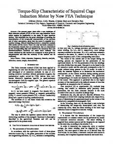
Figure 1. A sample Petri net. Petri nets (Fig. 1) are widely used to formally capture the dynamic semantics of concurrent systems due to their easy-to-understand visual notation and the wide range of available analysis tools. Petri nets are bipartite graphs, with two disjoint sets of nodes: Places and Transitions. 2
Places may contain an arbitrary number of Tokens. A token distribution defines the state of the modelled system. The state of the net can be changed by firing enabled transitions. A transition is enabled if each of its input places contains at least one token and no place connected with an inhibitor arc contains a token (if no arc weights are considered). When firing a transition, we remove a token from all input places (connected to the transition by Input Arcs) and add a token to all output places (as defined by Output Arcs).
3.1
the V IATRA 2 framework [23]. A simulation rule is executed in a model context, which consists of model elements satisfying constraints prescribed by the enabledness condition. These contexts are implicitly defined by matches of graph patterns defining an enabledness condition. 3.2.1 Enabledness condition Graph patterns represent conditions (or constraints) that have to be fulfilled by a part of the model in order to execute some manipulation steps on the model. The basic pattern body contains entity and relation definitions, which are to be matched when evaluating the pattern. Patterns may call other patterns using the find keyword, which enables the reuse of existing patterns as a part of a new (more complex) one. The semantics of this reference is similar to that of Prolog clauses: the caller pattern can be fulfilled only if their local constructs can be matched, and if the called (or referenced) pattern is also fulfilled. A negative application condition (NAC, defined by a negative subpattern with the neg keyword) prescribes contextual conditions for the original pattern which are forbidden in order to find a successful match. Negative conditions can be embedded into each other (e.g. negations of negations). As an example, the firing enabledness condition for a Petri net transition may be expressed using a graph pattern as shown in Fig. 3. This pattern uses nested negative application conditions to express that a Transition is enabled if every input Place instance connected to the Transition instance has at least one Token instance associated and no inhibitor input Place instance contains tokens. In this example, embedded NACs are used to express universal quantification with double negation of existence.
Metamodels of Petri nets
As the first step, we described the abstract syntax of Petri nets by metamodeling. For this purpose, we use the VPM (Visual and Precise Metamodeling) [24] approach, which can support different metamodeling paradigms by supporting multi-level metamodeling with explicit and generalized instance-of relations. The VPM language consists of two basic elements: the entity (a generalization of MOF package, class, or object) and the relation (a generalization of MOF association end, attribute, link end, slot). Entities represent basic concepts of a (modeling) domain, while relations represent the relationships between other model elements. In graph terminology, entities can be interpreted as nodes while relations are edges. Entities in a metamodel define node types while entities in models are simply referred to as nodes. In the paper, we use the VPM terminology for models to avoid the overloading of terms “node” and “edge”, also used in the context of RETE networks in Sec. 4. A simple Petri net metamodel, represented in V IATRA 2, is shown on Fig. 2.
pattern transitionFireable(T)= { transition(T); neg pattern notEnabled(T)= { place(P); outArc(OutArc, P, T); neg pattern placeToken(P)= { token(Tok); tokens(_X, P, Tok); } } or { // inhibited pattern place(P); inhibitorArc(OutArc, P, T); token(Token); tokens(_X, P, Tok); } }
Figure 2. Petri net metamodel in VIATRA.
3.2
Specifying simulation rules
The dynamic semantics of a domain-specific language is described in our approach by simulation rules. A rule R = (EC, AS) is defined by an enabledness condition EC and an action sequence AS, which describes model manipulation. Formally, an enabledness condition corresponds to a graph pattern, and model manipulation can be described by graph transformation (GT)) or abstract state machine (ASM) rules as available in the transformation language of
Figure 3. Petri-net firing condition
3.2.2 Action sequence for firing Graph transformation (GT) [7] provides a high-level rule and pattern-based manipulation language for graph models. In V IATRA 2, graph transformation rules may be specified 3
by using a precondition (or left-hand side – LHS) pattern determining the applicability of the rule, and a postcondition pattern (or right-hand side – RHS) which declaratively specifies the result model after rule application. Elements that are present only in (the image of) the LHS are deleted, elements that are present only in the RHS are created, and other model elements remain unchanged. Further actions can be initiated by calling any ASM instructions within the action part of a GT rule, e.g. to generate code. For instance, a GT rule may specify how to remove (or add) a token from a place, as shown in Fig. 4.
partial matches of a graph pattern. A partial match enumerates those model elements which satisfy a subset of the constraints described by the graph pattern. In a relational database analogy, each node stores a view. Matches of a pattern are readily available at any time, and they will be incrementally updated whenever model changes occur. Input nodes serve as the underlying knowledge base representing a model. There is a separate input node for each entity type (class), containing a view representing all the instances that conform to the type. Similarly, there is an input node for each relation type, containing a view consisting of tuples with source and target in addition to the identifier of the edge instance. At each intermediate node, set operations (e.g. filtering, projection, join, etc.) can be executed on the match sets stored at input nodes to compute the match set which is stored at the intermediate node. The match set for the entire pattern can be retrieved from the output production node. Based on the V IATRA 2 language constructs, we identify the following RETE nodes:
// Removes a token from ’Place’ gtrule removeToken (in P, in T)= { precondition find sourcePlaceWithToken // pattern call (T, P, Tok); postcondition find sourcePlaceWithoutToken (T, P, Tok); } // Adds a token to ’Place’ gtrule addToken (in P, in T)= { precondition find targetPlaceWithoutToken (T, P, Tok); postcondition find targetPlaceWithToken (T, P, Tok); }
• Join. The key component of a RETE is the join node, which performs a natural join on its input nodes in terms of relational algebra. • Pattern call. An important feature of the RETE algorithm is that network parts can be shared between patterns, thus reducing space and time complexity. When a pattern calls another pattern, it can simply use the appropriate production node to obtain the set of tuples conforming to the other pattern.
Figure 4. Graph transformation rules for adding and removing tokens Using these constructs, complex simulation steps can be described. Listing 1 shows a sequence which executes transformation rules simulating the firing of a transition, i.e., the removal of tokens from input places and the addition of tokens to output places.
• Negative conditions. A negative node contains the set of tuples stored at the primary input which do not match any tuple from the secondary input (which corresponds to anti-joins in relational databases).
rule fireTransition(in T) = seq { /* remove tokens from all input places */ forall Place with find inputPlace(T, P) do apply removeToken(T, Place); // GT rule invocation /* add tokens to all output places */ forall Place with find outputPlace(T, P) do apply addToken(T, Place); }
• OR-Patterns. Since OR-patterns are treated as a disjunction of independent pattern bodies, a separate matcher can be constructed for each body by sharing the production node, which will perform a union operation on the sets of tuples conforming to each body.
Listing 1. Simulation rule transition firing
Updates after model changes. Model changes are propagated through the network, modifying the match sets stored at the nodes incrementally, since each node only recomputes a partial matching. Input nodes receive notifications about changes on the model, regardless whether the model was changed programmatically (i.e. by executing a transformation) or by user interface events. Whenever a new model element is created or deleted, the input node of the appropriate type will release an update token on each of its outgoing edges. Such an update token represents changes in the partial matches stored by the RETE node. Positive update tokens reflect newly
4 Tracking enabledness with incremental pattern matching In this paper, we rely upon the incremental pattern matcher component of the V IATRA 2 framework [3], which adapts the RETE algorithm, a well-known technique in the field of rule-based systems. RETE network for graph pattern matching. RETEbased pattern matching relies on a network of nodes storing 4
added tuples, and negative updates refer to tuples being removed from the set. pattern transitionFireable(T)= { transition(T); neg pattern notFireable(T) = { find notEnabled(T); } or { find isInhibited(T); } }
Upon receiving an update token, a RETE node determines how the set of stored tuples will change, and release update tokens of its own to signal these changes to its child nodes. This way, the effects of an update will propagate through the network, eventually influencing the result sets stored in production nodes. The match set can be retrieved from the network instantly, i.e. there is no computation involved, which makes pattern matching a very efficient process. As a trade-off, there is increased memory consumption, and since stored result sets have to be continuously maintained, this imposes an overhead on update operations.
Figure 6. RETE matcher: ’transitionFireable’
5 Interactive simulation In this section, we provide a detailed description of our simulation framework based on the foundations of Sections 3 and 4. While graph transformation has already been used as a specification mechanism for interactive simulations of DSMs, our main conceptual novelty lies in the underlying incremental pattern matching, which provides significant increase in performance, and allows strong integration between model editing and simulation.
Example. As an example, we gradually construct a RETEbased pattern matcher capable of matching the pattern transitionFireable, which, in turn, is the enabledness condition for the Petri net firing simulation rule (Fig. 3). Its incremental tracking will allow to immediately find active contexts for a simulation step, which significantly speeds up simulation.
5.1
The simulation process
Using the simulation rules defined in Sec. 3.2, the system manages the simulation process by an implicitly defined state transition system. A state encodes the information describing which simulation rules are enabled for which contexts (e.g. in the Petri net example, a state could be “transitions t1 and t2 are enabled”). A state transition occurs when a simulation rule is executed for a specific context. Depending on the execution mode, the rule execution can be triggered (i) automatically, in the case of as-long-as-possible simulation, when the system runs until there is at least one enabled rule; (ii) by the user, in the case of debug-style stepping execution. When there are multiple enabled rules, such non-determinism can be resolved automatically, or by the user (choosing a rule to execute through the graphical interface). After a simulation rule has been executed, the next state is determined by the evaluation of the enabledness conditions. Since the matching sets of patterns corresponding to enabledness conditions are incrementally tracked by the underlying RETE network, the calculation of the actual state is carried out instantaneously. The most important phases of the simulation process in the Petri net example are illustrated on Fig. 7.
pattern sourcePlace(T, P) = { transition(T); place(P); outArc(A, P, T); }
Figure 5. RETE matcher for ’sourcePlace’
Figure 5 shows a RETE network matcher built for the sourcePlace pattern illustrating the use of join nodes. By joining three input nodes (the top-most nodes on Fig. 5), this sample RETE net enforces two entity type constraints (’Place’ and ’Transition’ entity types on the left and right input nodes) and an edge (connectivity) constraint (corresponding to the relation connecting the ’Place’ and ’Transition’ entity types), to find pairs of Places and Transitions connected by an out-arc. Figure 6 shows the matcher for pattern transitionFireable, containing a negative pattern with two bodies. In this case, each body is a simple reference to a previously constructed pattern, connected to a single production node for the inline pattern. The referenced patterns notEnabled(T) and isInhibited(T) are slightly compacted version of the real pattern definitions.
1. The simulation begins by the evaluation of all enabledness conditions; for the single simulation rule of the Petri net example, this is done by retrieving the matching set for the isTransitionFireable pattern (Fig. 6) 5
(a) Initial state
(b) Choice point
(d) On-the-fly model editing
pleted) where the user has fired the join transition and removed a token from the output place of exit, which does not influence any enabledness condition. It is important to note that user editing may only occur when the simulation engine is stopped after a rule has been executed; all rule executions occur in a transaction to ensure domain consistency. Additionally, transformation rules (with enabledness conditions and action sequences) can be added, changed, and removed dynamically, since the construction of RETE networks is dynamically performed as pattern definitions are loaded. This feature is analogous to “hot code replace” found in modern program debuggers, and very important for agile development.
(c) Trap state
(e) Final state
Figure 7. Petri net simulation phases from the RETE network. For the sample Petri net in Fig. 7(a), the initial matching set only includes the fork transition. Thus, the initial simulation state has been calculated; since there is only one enabled transition, the user may proceed by firing that transition, or by invoking the automatic execution mode to proceed to the next simulation state. 2. Fig. 7(b) shows the sample Petri net after the fork transition has been fired. As the Token model elements have been moved by the simulation rule, the RETE network was automatically updated to indicate that now transitions join and exit are enabled. Since two possible continuation paths exist, this non-determinism may be resolved randomly (in case of automated execution) or by user choice (guided simulation). If the exit transition is chosen, the system will reach a trap state (Fig. 7(c)). In a trap state, no enabledness conditions are fulfilled, thus there are no possible continuation paths. 3. As the simulation system is fully integrated into the ViatraDSM domain-specific modeling framework, the user can make various changes as the simulation is being executed. The simulation engine calculates the simulation state incrementally based on the actual model, the user may influence the simulation process by editing the model on-the-fly. In Fig. 7(d), two possible editing actions are shown: the user may re-enable the transition join by either placing a new token into the empty input place (denoted with 1), or delete the input arc (denoted with 2). In both cases, the RETE network is automatically updated following the editing action, moving the simulation system back into a state where join is enabled for firing. This feature is analogous to variable overwriting in program debuggers, however it allows for modifications on the DSM level. The user may also execute model editing which does not influence the simulation state. Fig. 7(e) shows a possible final state for the simulation (when a cycle has been com-
Figure 8. Running a simulation in the Petri net editor. In Fig. 8, the Petri net simulation is displayed in the concrete syntax model (diagram), shown on the left. In addition to the synchronization of abstract syntax models (tree viewer) and diagrams, the system provides an extensible programming interface to provide decoration for elements included in the context of simulation rules; in Fig. 8, fireable transitions are highlighted with red colour.
5.2
Performance
From the point of view of performance, the most relevant benchmarks for system simulation are the execution time for simulation sequences as a function of the complexity (size) of models. While a concise and detailed benchmark report is out of scope for the current paper, we present some initial measurements. Concerning execution time, an initial performance benchmark was published for our RETE-based incremental pattern matcher in [3]. The results have shown that the incremental approach in itself can provide a speed-up of two orders of magnitude (compared to local search-based non-incremental pattern matchers) for as-long-as-possible type model transformations, such as Petri net simulation. This is explained by the fact that the RETE network drastically reduces computation time for iterative pattern matching, which is traditionally the most costly phase. In our Petri 6
net benchmark, we used a real analysis model developed in the HIDENETS [22] European Union research project, consisting of 63 places, 69 transitions, and 302 arcs. Our simulator was capable of firing 10000 consecutive transitions within 3-4 seconds on a modern desktop computer. Since the RETE network essentially sacrifices memory consumption for speed, we have also concluded some initial investigations on how much memory is consumed for the benchmark used in [3]. With the Java VM version 1.6.0, the RETE network constructed for the mentioned Petri net graph consumed about 5 megabytes. While the size of the network may vary intensively with the pattern size, the contents of a pattern, and the model sizes, the incremental pattern matching guarantees that as long as there is enough memory, the execution will be fast.
The Generic Modeling Environment (GME) [10] combined with the GReAT model transformation engine [14] provides similar functionality outside the Eclipse world. With respect to model simulation, the GME/GReAT approach [1, 13] emphasizes the notion of semantic anchoring, which is targeting the specification of dynamic semantics, and not its implementation or simulation. The VMTS [16] framework also provides support for domain-specific modeling and model transformations by providing plugins for Microsoft Visual Studio. It offers core editing functionalities comparable to Eclipse GEF, but further manual coding is required for visual syntax and editing functionality. Its distinguishing feature is an optimizing OCL processor for the efficient handling of wellformedness constraints. Advanced multi-domain modeling features are supported by ATOM3 [6], which defines the concept of view metamodels sharing a common metamodel of a visual language. The consistency of different views and abstract-toconcrete syntax mappings [11] is maintained by triple graph grammars (TGG) [20] while simulators are also defined by graph grammar rules. In an interesting case study [12], the ATOM3 tool is used to create a simulator for Timed Transition Petri Nets, using the parallel graph transformation technique. However, the domain-specific model editor and the simulator are implemented as separate components, not as an integrated environment as in our case. As the main novelty of the current paper compared to all above DSM approaches using graph transformation as a specification formalism, we use incremental pattern matching as the underlying implementation, which provides significant speed up for simulation. While the concepts of incremental pattern matching was presented in previous papers of the authors [3, 25], none of these papers discussed its application to the simulation of domain-specific languages, which is the focus of the current paper.
6 Related work While industrial environments such as MetaEdit+ [17], Microsoft DSL Tools [18], and the Eclipse Graphical Modeling Framework [21] provide advanced facilities for the specification of domain-specific languages, they lack high-level support for model execution. For example, in MetaEdit+, simulations can be implemented by handcoding using an API. Microsoft DSL Tools and GMF both concentrate on a generative approach to ease the development of modeling environments; model execution and transformation in general are yet to be integrated. While OpenArchitectureWare [4] can be integrated into GMF editors to provide support for constraint evaluation, currently, there is no support for the utilisation of other features, such as the execution of transformations specified in the xTend Model Transformation language. There are also several academic DSM frameworks which are complemented with support for model transformations, typically, using a graph transformation [7] based approach, which approaches show the closest correspondence with our ViatraDSM framework. The TIGER project [9] (which is a conceptual continuation of GenGEd [2] from the 90s) primarily aims at generating syntax-directed editors as Eclipse plugins based upon the EMF and GEF technologies and a graph transformation engine. TIGER is able to generate GMF-based editors with rich and complex editing facilities (such as the execution of an editing action based on a single graph transformation rule). However, since TIGER lacks a control flow language, complex simulation steps can only be implemented in Java. DiaMeta (a follow-up of DiaGen [15]) replaces hypergraph grammars by MOF as provided by the MOFLON tool suite [19] to allow users not only to specify domain-specific modeling languages but also to generate corresponding diagram editors.
7 Conclusion In the paper, we presented a discrete event interactive simulation framework for dynamic domain-specific modeling languages. The dynamic semantics of a language was captured by a combination of graph transformation and abstract state machine rules as provided by the transformation language of the V IATRA 2 framework. As the main novelty compared to previous approaches using graph transformation for simulation purposes, our approach is built upon an incremental graph pattern matching engine, which instantly identifies all contexts where the enabledness condition of a simulation rule is enabled. This is carried out by incrementally keeping track of matches of graph patterns related to enabledness conditions. As a result, simulations requiring complex model changes (even 7
with intensive creation and deletion of objects) can be executed in an efficient way. As a main feature from the user’s point of view, our simulation framework enables efficient debugging of a model by allowing the user to edit the model any time during interactive simulation. Furthermore, simulation rules can also be added on the fly. In the future, we plan to investigate the use of incremental pattern matching techniques for other challenges of domain-specific modeling languages. A primary candidate is to provide synchronization of abstract and concrete syntax by capturing abstract-to-concrete syntax mappings by transformations, and propagating changes in an incremental way.
[11] E. Guerra and J. de Lara. Event-driven grammars: Towards the integration of meta-modelling and graph transformation. In Proc. 2nd International Conference on Graph Transformation, volume 3256 of LNCS, pages 54–69. Springer, 2004. [12] G. T. J. de Lara, C. Ermel and K. Ehrig. Parallel Graph Transformation for Model Simulation applied to Timed Transition Petri Nets. In Proc. Fourth International Workshop on Graph Transformation and Visual Modeling Techniques. ENTCS, 2004. [13] K. Chen, J. Sztipanovits, S. Neema. Toward a Semantic Anchoring Infrastructure for Domain-Specific Modeling Languages. In Proc. 5th ACM international conference on Embedded software, pages 35–43. ACM Press, New York, NY, USA, 2005. [14] G. Karsai, A. Agrawal, F. Shi, and J. Sprinkle. On the use of graph transformation in the formal specification of model interpreters. Journal of Universal Computer Science, 2003. [15] O. K¨oth and M. Minas. Generating diagram editors providing free-hand editing as well as syntax-directed editing. In GRATRA 2000 Joint APPLIGRAPH and GETGRATS Workshop on Graph Transformation Systems, pages 32–39, Berlin, Germany, March 25–27 2000. [16] T. Levendovszky, L. Lengyel, G. Mezei, and H. Charaf. A systematic approach to metamodeling environments and model transformation systems in vmts. In Proc. International Workshop on Graph Based Tools. Elsevier, 2004. [17] Metacase. MetaEdit+. http://www.metacase.com/ mep/. [18] Microsoft. DSL Tools. http://lab.msdn. microsoft.com/teamsystem/workshop/ dsltools/default.aspx. [19] M. Minas. Generating visual editors based on FUJABA/MOFLON and DiaMeta. Technical report, University Paderborn, 2006. Proc. 4th Fujaba Days, pp. 35-42, Technical Report tr-ri-06-275. [20] A. Sch¨urr. Specification of graph translators with triple graph grammars. In Proc. WG94: International Workshop on Graph-Theoretic Concepts in Computer Science, number 903 in LNCS, pages 151–163. Springer, 1994. [21] The Eclipse Project. Graphical Modeling Framework. http://www.eclipse.org/gmf. [22] The HIDENETS Project. HIghly DEpendable ip-based NETworks and Services. http://www.hidenets. aau.dk. [23] D. Varr´o and A. Balogh. The model transformation language of the VIATRA2 framework. Science of Computer Programming, 68(3):214–234, October 2007. [24] D. Varr´o and A. Pataricza. VPM: A visual, precise and multilevel metamodeling framework for describing mathematical domains and UML. Journal of Software and Systems Modeling, 2(3):187–210, October 2003. [25] G. Varro, D. Varro, and A. Schuerr. Incremental graph pattern matching: Data structures and initial experiments. In Proceedings of the 2nd International Workshop on Graph and Model Transformation, Brighton, United Kingdom, September 2006.
References [1] A. Agrawal, G. Karsai, A. Ledeczi. An End-to-End DomainDriven Software Development Framework. In Proc. 18th ACM SIGPLAN conference on Object-oriented programming, systems, languages, and applications, pp. 8–15. ACM Press, New York, NY, USA, 2003. [2] R. Bardohl and H. Ehrig. Conceptual model of the graphical editor GENGED for the visual definition of visual languages. In Proc. Theory and Application to Graph Transformations, volume 1764 of LNCS, pages 252–266. Springer, 2000. ¨ os, I. R´ath, D. Varr´o, and G. Varr´o. [3] G. Bergmann, A. Okr¨ Incremental pattern matching in the VIATRA transformation system. In GRaMoT’08, 3rd International Workshop on Graph and Model Transformation. 30th International Conference on Software Engineering, 2008. Accepted. [4] Bernd Kolb, Markus V¨olter. openArchitectureWare and Eclipse. http://architecturware. sourceforge.net/data/oawEclipse.pdf. [5] E. B¨orger and R. S¨ark. Abstract State Machines. A method for High-Level System Design and Analysis. SpringerVerlag, 2003. [6] J. de Lara and H. Vangheluwe. AToM3: A tool for multiformalism and meta-modelling. In Proc. 5th International Fundamental Approaches to Software Engineering Conference, Grenoble, France, volume 2306 of LNCS, pages 174– 188. Springer, 2002. [7] H. Ehrig, G. Engels, H.-J. Kreowski, and G. Rozenberg, editors. Handbook on Graph Grammars and Computing by Graph Transformation, volume 2: Applications, Languages and Tools. World Scientific, 1999. [8] H. Ehrig, U. Montanari, H.-J. Kreowski, and G. Rozenberg, editors. Handbook on Graph Grammars and Computing by Graph Transformation, volume 3: Concurrency and Distribution. World Scientific, 1999. [9] K. Ehrig, C. Ermel, S. H¨ansgen, and G. Taentzer. Generation of visual editors as Eclipse plug-ins. In 20th IEEE/ACM Conference on Automated Software Engineering, Long Beach, CA, USA, pages 134–143. ACM, 2005. [10] GME. The Generic Modeling Environment. http:// www.isis.vanderbilt.edu/Projects/gme.
8