proceedings Proceedings
Designing a Rogowski Coil with Particle Swarm Optimization † Guillermo Robles 1 ,* , Muhammad Shafiq 2 1 2
* †
and Juan Manuel Martínez-Tarifa 1
Department of Electrical Engineering, Universidad Carlos III de Madrid, Avda, Universidad, 30, Leganés, Madrid 28911, Spain Department of Electrical Engineering, University of Vaasa, Vaasa, Finland;
[email protected] Correspondence:
[email protected] Presented at the 5th International Electronic Conference on Sensors and Applications, 15–30 November 2018; Available online: https://sciforum.net/conference/ecsa-5.
Received: date; Accepted: date; Published: date
Abstract: Rogowski coils are inductive sensors based on Faraday’s and Ampère’s Laws to measure currents through conductors without galvanic contact. The main advantage of Rogowski coils when compared with current transformers is the fact that the core is air so they never saturate and the upper cut-off current can be higher. These characteristics makes Rogowski coils ideal candidates to measure high amplitude pulsed currents. On the contrary, there are two main drawbacks. On the one hand, the output voltage is the derivative of the primary current so it has to be integrated to measure the original signal; and, on the other hand, the transfer function is resonant due to the capacitance and the self-inductance of the coil. The solution is the use of a passive integration with a terminating resistor at the output of the sensor that splits the two complex poles and gives a constant transfer function for a determined bandwidth. The downside is a loss of sensitivity. Since it is possible to calculate the electrical parameters of the coil based on its geometrical dimensions, the geometry can be adapted to design sensors for different applications depending on the time characteristics of the input current. This paper proposes the design of Rogowski coils based on their geometric characteristics maximizing the gain-bandwidth product using particle swarm optimization and adapting the coil to the specific requirements of the application. Keywords: Rogowski coils; particle swarm optimization; gain-bandwidth product; current measurement; magnetic field measurement
1. Introduction Among high frequency current measurement sensors, current transformers with ferrite cores and Rogowski coils are the preferred solution especially due to their non-intrusive measurement capability [1]. However, based on critical parameters such as: cost, bandwidth, sensitivity, saturation, linearity, operating temperature, integrability, flexibility and isolation, and material technology, Rogowski coils have been considered as the favorite tool in industrial applications [2]. Nowadays, Rogowski coils are being used in various measurement applications not only under normal operation but as in fault situations such as AC and transient measurements, partial discharges, ground faults, and relay protection tasks [2] with the capability of measuring the signals with frequency ranging from few Hz up to several MHz and the amplitude of few Amperes to above kA. The physical layout of the coil, signal processing, and signal integration are the important issues in the design of these type of sensors [3]. A lot of work has been published on the design and analysis of Rogowski coils and still there are various aspects that need to be explored further to improve its performance [1]. The selection of suitable geometrical parameters has been identified as an important aspect regarding a proper operation and installation of the coil around the under test power component [4,5]. Proceedings 2018, xx, 5; doi:10.3390/proceedingsxx010005
www.mdpi.com/journal/proceedings
Proceedings 2018, xx, 5
2 of 6
These parameters determine the electrical parameters and significantly affect the measuring performance of the coil in terms of its sensitivity and bandwidth. Higher sensitivity and wider bandwidth are generally desired for a better design of the Rogowski coil sensor; however, changing one geometrical parameter may affect the sensitivity and bandwidth in reverse manners: an increase in sensitivity and decrease in bandwidth at the same time and vice versa [4]. Therefore, it is quite challenging to develop a design of Rogowski coil that maximize the sensitivity and bandwidth of the coil simultaneously for current measurement based on an arbitrary selection of the geometry. In this paper, a formulated method will be presented to determine the optimized geometrical parameters based on the Particle Swarm Optimization (PSO) technique in order to have the maximum sensitivity for a certain bandwidth. 2. Rogowski coil Geometry and Electrical Parameters The behavior of a Rogowski coil in terms of sensitivity and bandwidth is determined by its electrical parameters: resistance R, self-inductance L, capacitance between the winding and the returning turn Cl and capacitance between turns Ct . In most cases, Ct is negligible compared with Cl so, henceforth, we will only consider Cl . Finally, M is the mutual inductance between the primary conductor and the coil. These parameters can be expressed in function of the geometry of the coil with the following equations [6]: 4l R=ρ 2 (1) πd L=
µ0 2 b N h log 2π a
Cl =
M=
π 2 e0 ( a + b ) √ 2 A/π log d µ0 b Nh log 2π a
(2) (3)
(4)
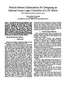
where, according to Figure 1, a is the internal diameter of the coil, b is the external diameter, h is the height of the coil, N is the number of turns and A = (b − a)h/2 is the area of a turn. Additionally, d and l are the diameter and the total length of the wire, respectively; ρ, µ0 and e0 are the resistivity of copper, the magnetic permeability and permittivity of air, respectively.
Figure 1. Geometrical parameters of a Rogowski.
Proceedings 2018, xx, 5
3 of 6
3. Frequency Response of a Rogowski coil Considering the equivalent circuit in lumped parameters shown in Figure 2, the output of the Rogowski coil in volts can be obtained with the transfer function shown in (5). Using the electrical parameters from a Rogowski coil manufactured and characterized in Aalto University, L = 1.2 µH, Cl = 5.7 pF, M = 9.51 µH and considering R = 0.1 Ω, the resulting Bode plot is represented in Figure 3. The resistance for the selected Rogowski coil is actually R = 0.005 Ω in direct current for N = 30 and an AWG 18 wire. However, the bandwidth of these type of sensors can reach tens of megahertz so it has been decided to multiply the resistance 20 times to take into account the skin effect, a value similar to those obtained from previous works in this frequency range. Nevertheless, this resistance can be neglected in most cases and do not contribute to the frequency response notably. It can be seen in the Bode plot that the output voltage v(t) is the derivative of the input i (t) (when the phase is +90◦ ) up to √ frequencies close to the resonance frequency in f 0 = 1/2π LCl = 60.8 MHz. Vo (s) =
LCl
s2
Ms I (s) + RCl s + 1
(5)
Figure 2. Electrical model of a Rogowski coil considering lumped parameters.
Figure 3. Frequency response of an underdamped second order system corresponding to a Rogowski coil.
There is the possibility of obtaining an output voltage proportional to the input voltage using a resistor at the ends of the Rogowski coil that will split the complex pole into two poles [3]. Consider the
Proceedings 2018, xx, 5
4 of 6
transfer function in Equation (6) which includes a generic terminating resistance Rt = 10 Ω in parallel with the capacitance in Figure 2. Now, there is a band of frequencies between 10 MHz and 100 MHz where the input and the output are in phase so the output is proportional to the input, see plot in Figure 4. Unfortunately, the sensitivity of the coil drops to close −30 dB. Vo (s) =
Rt Ms I (s) LRt Cl s2 + ( L + RRt Cl )s + R + Rt
(6)
Figure 4. Frequency response of a Rogowski coil with terminating resistance.
4. Optimizing the Geometry of a Rogowski coil The objective now is the design of a self-integrating Rogowski coil optimizing the gain-bandwidth product (GBWP) to minimize the loss of sensitivity while maximizing the bandwidth of the coil. The optimization function will be based on the geometrical parameters and, hence, the electrical parameters will also be determined. Then, the design variables will be a, b, h, N and Rt , being the last one the most important to select the gain of the Rogowski coil. There are also some spatial constraints: the internal diameter should be large enough to allow the passing of the primary conductor so it has been set to a minimum of 10 cm. The external diameter should be larger than a and with an upper bound set to 30 cm so the coil do not interfere with close instrumentation. The height of the coil has to be selected between 1 cm and 4 cm for the same reasons. Additionally, the minimum number of turns is N = 3 and the minimum terminating resistance Rt = 10 Ω. Finally, the bandwidth will be chosen between 150 kHz and 150 MHz to be able to measure currents in the HF-VHF ranges. Notice that, since the transfer function is second order, the effective band of frequencies where the input and output are in phase would be very narrow. The optimization method is based on particle swarm optimization (PSO) in a five dimensions space corresponding to the five design parameters. This method places a flock or swarm of particles randomly in the solution space [7]. In every iteration l, every particle evaluates the GBWP in its position determined by the design parameters. The best solution for the GBWP of each particle k, Pk,best (l ) is registered and updated in every iteration, as well as the best global solution of all the swarm, Pbest (l ). These two possible solutions are part of the swarm intelligence so every particle knows its own best fit and the particle with the best approximation to the solution. Then, the positions
Proceedings 2018, xx, 5
5 of 6
of the particles are changed considering the velocity of particle k that ties it to its best position and another component that moves the particle towards the global best, [8] according to Equations (7). v k ( l + 1)
= vk (l ) + U1 (0, 1) ⊗ [Pk,best (l ) − Pk (l )] + U2 (0, 1) ⊗ [Pbest (l ) − Pk (l )],
P k ( l + 1)
(7)
= P k ( l ) + v k ( l + 1).
with U1 (0, 1) and U2 (0, 1) five dimensions line matrices whose elements are uniformly distributed between 0 and 1. After running the algorithm with a swarm of 2000 particles, the resulting parameters for the optimized Rogowski coil are presented in Table 1. The geometrical parameters lead to higher values of b and h than those from the coil of Figure 4, as expected from previos studies [6]. In addition, the use of higher values of Rt are consistent with an increase of the gain. Table 1. Parameters of the Rogowski coil optimizing the GBWP. Parameter
Value
a b h N Rt
10 cm 19.9 cm 4 cm 205 turns 226.5 Ω
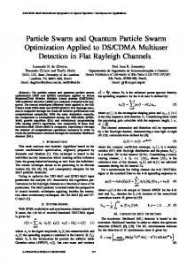
The resulting Bode plot for the designed coil is represented in Figure 5 where it can be seen that the bandwidth goes from 810 kHz to 2.4 MHz considering that the phase shift introduced by the transfer function is sufficiently close to 0◦ provided it is in the interval between 10◦ and −10◦ . The gain is close to 0 dB being much larger than in the case presented in Figure 4 and the bandwidth is the widest for that gain.
Figure 5. Frequency response of the designed Rogowski coil.
Proceedings 2018, xx, 5
6 of 6
5. Discussion This work has proposed a flexible method to design a Rogowski coil with optimum gain-bandwidth parameters. The equations relating the geometrical characteristics with the electrical properties of a Rogowski coil are based on the assumption that the values of resistance, inductance and capacitance are not distributed along the wire. This is true if the length of this wire is short compared with the wavelength of the voltage and current in the coil. Considering the designed coil, it can be found that the length of a turn is 0.18 m and the total length of the wire would be 36.9 m plus the length of the returning coil. The wavelength of signals with a frequency of 1 MHz traveling at the speed of light is 300 m so the assumption about the lumped model would be consistent with these signals. Nevertheless, the design is close to the need of considering a distributed model so it would be necessary to construct the coil and test its frequency response especially for signals near to the high cut-off frequency in 2.4 MHz. In any case, the method presented is notably flexible so other geometries and constraints can be applied to optimize any type of Rogowski coil. Author Contributions: The idea of the paper and the implementation of the algorithm was done by G.R. A thorough review of the state of the art and the manufacturing of the generic Rogowski coil at Aalto University was made by M.S. The analysis of the results was made by G.R. and J.M.M-T. The writing, review and editing of the paper was done by all the authors. Funding: This research has received funds from the Academy of Finland under the Grant No. 309412 and the Spanish Government (MINECO) and the European Regional Development Fund (ERDF) under contract DPI2015-66478-C2-1-R (MINECO/FEDER, UE). Conflicts of Interest: The authors declare no conflict of interest.
References 1. 2. 3. 4. 5. 6.
7.
8.
Samimi, M.H.; Mahari, A.; Farahnakian, M.A.; Mohseni, H. The Rogowski Coil Principles and Applications: A Review. IEEE Sens. J. 2015, 15, 651–658. Hu, C.; Li, H.b.; Jiao, Y.; Zhang, Z.; Li, K. Comparative analysis of various models of Rogowski coil for very fast transient study. IEEJ Trans. Electr. Electron. Eng. 2018, 13, 1319–1327. Argüeso, M.; Robles, G.; Sanz, J. Implementation of a Rogowski coil for the measurement of partial discharges. Rev. Sci. Instrum. 2005, 76, 065107. Shafiq, M.; Hussain, G.A.; Kütt, L.; Lehtonen, M. Effect of geometrical parameters on high frequency performance of Rogowski coil for partial discharge measurements. Measurement 2014, 49, 126–137. Liu, Y.; Lin, F.; Zhang, Q.; Zhong, H. Design and Construction of a Rogowski Coil for Measuring Wide Pulsed Current. IEEE Sens. J. 2011, 11, 123–130. Robles, G.; Martinez, J.M.; Sanz, J.; Tellini, B.; Zappacosta, C.; Rojas, M. Designing and tuning an air-cored current transformer for partial discharges pulses measurements. In Proceedings of the 2008 IEEE Instrumentation and Measurement Technology Conference, Victoria, BC, Canada, 12–15 May 2008; pp. 2021–2025. Kennedy, J.; Eberhart, R. Particle swarm optimization. In Proceedings of the ICNN’95—International Conference on Neural Networks, Perth, WA, Australia 27 November–1 December 1995; Volume 4, pp. 1942–1948. Poli, R.; Kennedy, J.; Blackwell, T. Particle swarm optimization. Swarm Intell. 2007, 1, 33–57. c 2018 by the authors. Licensee MDPI, Basel, Switzerland. This article is an open access
article distributed under the terms and conditions of the Creative Commons Attribution (CC BY) license (http://creativecommons.org/licenses/by/4.0/).