DESIGNING A USABLE INTERFACE FOR AN INTERACTIVE ROBOT Simeon Keates1, John Clarkson1 and Peter Robinson2 1 Department of Engineering, University of Cambridge 2 Computer Laboratory, University of Cambridge ABSTRACT The traditional emphasis of Rehabilitation Robotics has been dominated largely by the logistics of system development rather than how to maximise overall system usability [1]. The research programme at Cambridge has focused on the shortcomings of this approach and the identification of strategies for placing the user exclusively at the centre of the design process [2].
inspectors who handle the circuits under an optical microscope. The IRVIS system is being developed because the inspection process is fundamentally a visual task and potential inspectors are being excluded from this vocational opportunity because of the current reliance on the manual manipulation of the circuit. The use of IRVIS in the workplace will remove an unnecessary barrier to motion-impaired operators.
This paper describes the re-design of the interface for an Interactive Robotic Visual Inspection System (IRVIS) and how this was used to formulate a structured, methodical approach to user-centred interface design. A discussion of the original IRVIS interface design will be presented, followed by a description of current usability theory and its role in formulating the proposed five-level user-centred design approach. The results of the evaluation of this approach, through user trials, will also be discussed.
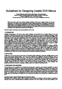
The IRVIS prototype A prototype IRVIS system was developed by Mahoney [3]. It consists of a movable tray with three degrees of freedom and a digital video camera mounted on a tilting gantry above with freedom to translate (Figure 1).
BACKGROUND The aim of the IRVIS system is to enable the remote inspection of hybrid microcircuits. Currently the inspection task is performed by able-bodied
Figure 1. The IRVIS System.
- 156 ICORR ’99: International Conference on Rehabilitation Robotics, Stanford, CA
This arrangement of five motors, whilst offering all the requisite functionality, resulted in complex kinematics to perform basic inspection tasks. For example, examining a wire bond from all possible angles involves tray and camera translation, tray rotation and gantry tilting. Consequently, a routine inspection procedure can involve all five motor axes. Interface design and user trials An interface for IRVIS was designed using the Cambridge University Robot Language (CURL - Figure 2). This was menu-driven, with the inspectors specifying the axis and magnitude of motion to be generated.
Figure 2. The CURL interface.
User trials at a local hybrid microcircuit manufacturer demonstrated the feasibility of the system, but highlighted a significant shortfall in overall usability. Put simply, the system was not meeting the
needs of the inspectors and a new interface was clearly required. NEW PRODUCT DESIGN There are three steps to be considered in developing all new products, such as IRVIS: (1) defining the problem to be addressed; (2) developing a solution and (3) evaluating the solution [4]. The following sections describe how these three stages were applied to IRVIS and subsequently subdivided to form a five-level design approach that is applicable to generic interactive system design. 1 - PROBLEM DEFINITION The problems with the original CURL interface were principally due to the users being unable to understand and predict the effects of commands entered through the interface and the resulting motion of the robot. The commands were too abstract and distant from the immediacy of manual circuit manipulation, resulting in a lack of feeling ‘in control’. The IRVIS system required a structure enabling intuitive direct control, rather than the more detached supervisory control offered by the CURL interface. It was quickly realised that an understanding of generic inspection routines was needed and data collection sessions were organised with the manufacturer involved in the original user trials. Experienced inspectors were video-recorded and study of the tapes provided detailed
- 157 ICORR ’99: International Conference on Rehabilitation Robotics, Stanford, CA
information on inspection procedures. The generic actions observed were classified into five categories: translation; rotation; tilting; zooming and focusing. 2 - DEVELOPING A SOLUTION Any approach to the development of interactive mechatronic systems needs to support the concurrent development of both the mechatronic hardware and the system interface, whilst retaining a central focus on usability. Usability approaches to design Nielsen [5] gives an account of the use of heuristics in a usability inspection method known as “heuristic evaluation”. Three of these heuristics directly address the observed shortcomings in the CURL interface and collectively form the basis of a design approach: • Visibility of system status - for the user to have sufficient feedback to have a clear understanding of the current state of the complete system; • Matching system and real world for the system to respond appropriately to changing user input; • User control and freedom - for the user to be have suitably intuitive and versatile controls for clear and succinct communication of intent.
Building on these heuristics, a design approach was developed that expands the second stage of the design process, solution development, into three specified steps. Each level of the resultant design process (Figure 3) is accompanied by motion-impaired user trials at the Papworth Trust throughout and a final evaluation period before progression to the next level, thus providing a framework with clearly defined goals for system usability. The role of the prototype An integral part of the design approach is the use of prototypes to embody the system at each stage of development. There are a number of forms that a prototype can take from low fidelity abstract representations through to high fidelity working models. Extending directly from the principles of prototype fidelity, a variable fidelity prototype for use in the IRVIS redevelopment was proposed at the previous ICORR conference [6]. This prototype was in essence a software simulation of the proposed system that encompasses both the appearance and functionality of the user interface and the mechanical properties of the robotic hardware.
- 158 ICORR ’99: International Conference on Rehabilitation Robotics, Stanford, CA
Level 1 - Problem specification specify the complete problem to be solved
view of the inspection tray (Figure 4). The user was able to select control over any one of the robot’s individual motors and to drive them by moving the cursor in the display windows and pressing either mouse button.
STAGE 1
verify problem definition Level 2 - Visibility of system status develop a minimal, but sufficient representation of the system verify user understanding Level 3 - Matching system and real world augment the behaviour of the model with simulated kinematics
Figure 4. The first interface revision. STAGE 2
Figure 3. The design approach.
Users were asked to predict the machine’s behaviour as a result of their input. Initially, the users had some difficulty understanding what was being presented to them and it quickly became clear that apparently simple details can make a substantial difference to the overall usability. Small changes such as the addition of a view cone, use of colour-coding and a little extra geometric detail led to a representation of the system that required almost no explanation. Users who encountered the final version of the interface were able to successfully perform simple positioning tasks.
Visibility of system status After developing a basic model of the system, work focused on the problem of defining a minimal, but sufficient, representation of the system for the user to be able to interact with. This version of the revised interface showed an overview of the robot and a camera
Matching system and real world Having established a representation that afforded sufficient feedback to the user, the next step was to include kinematic motion in the model. The user trials utilised in this stage of the research were to ensure that the simulated robot response to user input
verify system behaviour Level 4 - User freedom and control develop quality of control and consider ‘handling’ verify user comfort Level 5 - Evaluation / validation evaluate system usability
STAGE 3
validate system usability
- 159 ICORR ’99: International Conference on Rehabilitation Robotics, Stanford, CA
was consistent with that of the actual hardware. The kinematics used to drive the physical system were reconstructed in the virtual system and a clearer understanding of the nature of the user’s view of the geometry led to an intuitive set of driving controls. Discrepancies were identified between the anticipated and actual response behaviour. These were a result of weak assumptions made in the original interpretation of the robot system kinematics. Poor performance of operations such as rotation about a point had previously been attributed to mechanical inaccuracies; working within a simulated environment identified the control software as the origin. User freedom and control The next stage concentrated on assessing the ease of interaction between the user and the simulation interface, identifying particular aspects of the interface that required modification. From each of the previous levels, it was clear that all of the users wished to interact as directly as possible with the circuit and not with the motors. Consequently, the individual motor controls were replaced with generic movement types, specifically translation, rotation and tilt (Figure 5).
Figure 5. The final interface.
The size and direction of each of these inputs were directly proportional to the magnitude and direction of the input device movement. Thus the user could manipulate the circuit directly and the interface became easier to use. The speed-of-response parameters were also investigated to verify that the users were comfortable with ‘feel’ of the virtual robot. This was achieved by establishing a series of pseudoinspection tasks and acquiring interaction data that could be analysed. One of the most important improvements arising directly from the user trials was the development of a position control input paradigm to complement the original velocity control. Velocity control moves the cursor at a rate proportional to the displacement of the transducer from the central datum, whereas position control moves it by a distance proportional to this displacement. Position control proved to be both a quantitative and qualitative success. The users found the interface easier to interact with and more intuitive. Experiments showed that for all users
- 160 ICORR ’99: International Conference on Rehabilitation Robotics, Stanford, CA
the fastest times obtained under position and velocity control were similar. However, position control required lower levels of acceleration and velocity, requiring a less demanding mechanical specification for the robot. 3 - EVALUATION In order to assess the usability of the redesigned interface when used in conjunction with the robot, the IRVIS robot was transported to Papworth for user trials (Figure 6). Only one of the users had used the IRVIS robot before, but all had experience of the simulation.
Figure 6. User trial evaluation.
The evaluation exercise consisted of the users manipulating a hybrid microcircuit in each of the generic inspection modes (translation, rotation, etc.). Users were asked whether they felt that they were interacting directly with the robot and if the speed of response was too slow.
Qualitative feedback from all the users was extremely favourable. Each user found the new interface easy and intuitive to use and all completed the tasks with a minimum of guidance. No user complained of the speed of response of IRVIS being too slow. This was a significant result, because it had been previously thought that IRVIS was mechanically under-specified. The new interface showed that the cause of the problems was in the software implementation and not mechanical in origin, thus saving an expensive, and unnecessary, re-build. A representative from the manufacturer involved in the original evaluation of IRVIS declared the revised system to be fully fit for use and is pursuing quotes for remote inspection devices, based on the IRVIS specification. CONCLUSIONS The most important outcome from this research has been the development of a five-level approach to interactive system design. This approach provides a substantive framework for the design process, with specific usability goals throughout the design cycle. This structure and focus on usability is a key strength of the process over more traditional approaches. Validating the effectiveness of a design approach is difficult, but one way is to verify the success of products developed using it.. The significant increase in usability of the IRVIS
- 161 ICORR ’99: International Conference on Rehabilitation Robotics, Stanford, CA
interface shows that the design approach can yield notable improvements in a product’s fitness for purpose. Acknowledgements This project was funded by the Engineering and Physical Sciences Research Council. We thank Bob Dowland for his contribution to this work. We also gratefully acknowledge the staff and residents of the Papworth Trust for their time and efforts. References [1] Buhler C. “Robotics for Rehabilitation - A European(?) Perspective.” Robotica. 16(5). 487490. (1998).
[6] Dowland R, Clarkson PJ and Cipolla R. “A Prototyping Strategy for use in Interactive Robotic Systems Development.” Robotica. 16(5). 517521. (1998). Address Dr Simeon Keates Engineering Design Centre University of Cambridge Trumpington Street CAMBRIDGE. CB2 1PZ. UK. Tel: Fax: E-mail:
+44 (0)1223 332673 +44 (0)1223 332662
[email protected]
[2] Keates S, Robinson P. “The Role of User Modelling in Rehabilitation Robotics.” Proceedings of ICORR ’97. 75-78. (1997). [3] Mahoney RM, Jackson RD, Dargie GD. “An Interactive Robot Quantitative Assessment Test.” Proceedings of RESNA ’92. 110-112. (1992). [4] Keates S, Clarkson PJ, Robinson P. “Developing a methodology for the design of accessible interfaces.” Proceedings of the 4th ERCIM Workshop. 1-15. (1998). [5] Nielsen, J. Usability Inspection Methods, John Wiley & Sons, 1994.
- 162 ICORR ’99: International Conference on Rehabilitation Robotics, Stanford, CA