Designing and Verifying Communication Protocols using Model Driven Architecture and Spin Model Checker Prabhu Shankar Kaliappan, Hartmut Koenig
Vishnu Kumar Kaliappan
Chair Computer Networks and Communication Systems Brandenburg Technical University Cottbus, Germany {psk, koenig}@informatik.tu-cottbus.de
Department of Information & Communication Engineering Konkuk University Seoul, South Korea
[email protected]
Abstract: The need of communication protocols in today’s environment increases as much as the network explores. Many new kinds of protocols, e.g. for information sharing, security, etc., are being developed day-to-day which often leads to rapid, premature developments. Many protocols have not scaled to satisfy important properties like deadlock and livelock freedom, since MDA focuses on the rapid development rather than on the quality of the developed models. In order to fix the above, we introduce a 2-Phase strategy based on the UML state machine and sequence diagram to satisfy the properties of communication protocols. We convert these models into PROMELA code for execution on the SPIN model checker. The results are compared with the developed UML models.
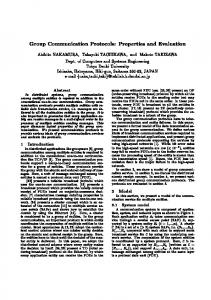
above problem we propose a 2-phase strategy (see Figure 1). In first phase, we model the behavior view by UML state charts and activity diagrams. Next they are translated as a combination of state charts with the semantics of activity diagrams into PROMELA (PROcess MEta Language) [3]. In the second phase, we design the communication view using UML sequence and timing diagrams. The model properties are translated into a temporal logic and imported together with the PROMELA code into the model checker SPIN (Simple Protocol INterpreter) [4] for verification. Accordingly our approach illustrates the verification property for communication protocols. UML Sequence Diagram
UML State Diagram
Keywords: UML modeling, Communication protocols, Protocol verification, SPIN tool PROMELA
I.
Temporal Property
INTRODUCTION
Due to the huge complexity of modern software systems, it is required to specify precisely what a software component should do and how it should behave [1]. If the final implementation deviates from the expected behavior, then the use of the developed component may fail. This also applies for the development of communicating protocols as they are merely implemented in the software. Currently, most of the protocols are developed through the natural, informal language because it is easy to understand. Special languages known as formal description languages (FDTs) have been developed for an unambiguous specification of the software. FDTs distinguish from programming languages by having a formal semantics. Programming languages, such as Java or C++, have only a formally defined syntax. In order to back-up such languages, the Unified Modeling Language 2 (UML 2) [2] is a collection of semi-formal standard notations and concepts for modeling software systems at different stages and views during their development. The development process is supported by the Model Driven Architecture (MDA) concept [10], which is initiated from the Object Management Group (OMG). The UML semantics is described in natural English language which includes semantic variation points that leave some semantics issues deliberately open. This desirable property represents a drawback from the verification point of view. To cope with the
SPIN Tool
Figure 1. 2-phase strategy
The paper is organized as follows. In Section 2 we give a short overview of related work. Section 3 illustrates the MDA approach applied to the development of communication protocols. Section 4 presents our 2-phase design and verification strategy using a case study as example. Some final remarks and an outlook on future work conclude the paper. II.
RELATED WORKS
An approach for the formal verification of UML diagrams, such as class, state and communication diagrams, is presented in [6]. The approach applies an object oriented language, called the Maude, for verifying the static and dynamic features of object oriented specifications. Maude is based on a rewrite logic. According to [7], there is no proof of correctness (due to the missing UML semantics), when a UML model is translated into PROMELA. To overcome this drawback the static and dynamic verification is carried out individually and integrated into the final validation stage. The verification of the UML class and activity diagrams is illustrated for a simple protocol
in [8] and [9]. The activity diagrams are converted into an FSM (based on behaviors). Thereafter the FSM is converted into PROMELA through an intermediate language. Most of the above specified approaches illustrate how to verify the UML state diagrams. The open issue is how to specify and verify communication protocol properties in detail. According to our concern, the protocols can be efficiently developed if they are verified simultaneously while modeling. In order to fulfill the concern, we specify and verify the protocol properties in the Platform Independent Model (PIM) and the Platform Specific Model (PSM) independently. III.
of the protocol primitives exchanged. Furthermore, the format (syntax) and the meaning (semantics) of the messages are defined. C. MDA and Communication Protocols The following template for the design of communication protocols consists of three components, namely: the model designer, the model mapper, and the system generator (see Figure 2). These are illustrated with respect to PIM, PSM, and the code generator in the following.
ARCHITECTURE TEMPLATE FOR COMMUNICATION PROTOCOLS
A. Model Driven Architecture Model driven architecture is an approach to software development based on the modeling and automated mapping of models. MDA has divided its components into two important parts, namely PIM and PSM, which are discussed in detail further as basis. The Platform Independent Model is a model with a high level of abstraction that is independent of any implementation technology [11]. A modeling language capable of generating all the required artifacts such as the Unified Modeling Language is required at this level. According to [10], the PIM provides two basic advantages. First, the person responsible for defining the functionality do not have to take any platform details into the consideration while modeling, which gives the designer a freedom to concentrate and focus only on the logical rule. Second, since the functionality is pure from any implementation details, it is easier to produce implementations on different platforms. The PIM is stored in the Meta Object Facility (MOF) and serves as the input to the mapping step which will produce a Platform Specific Model. The PSM’s can be described in one of two ways: (1) using UML diagrams (class, sequence, activity etc.) or (2) using interface definitions in a concrete implementation technology (IDL, XML, Java etc), but in both cases the behavior and constraints are specified using a formal notation (UML diagrams) or an informal notation (natural language). Automated tools will be used to map the platform independent models onto the specific platforms. The final step takes PSM as an input to produce the implementation for a particular platform using a transformation tool. B. Communication Protocols A communication is carried out between a sender and a receiver over a physical medium using an authorized service provider. The service is provided by means of communicating entities. These entities are active objects exchanging messages with their environment. The service users interact with the entities by exchanging service primitives through service access points (SAPs). Each SAP is uniquely mapped to an entity which handles the primitives and maps them on protocol primitives or protocol data units (PDUs), respectively, that are send to the peer entity. The exchange of the protocol primitives is based on rules which are specified by means of a communication protocol. A communication protocol describes the interacting behavior of the entities by specifying the timely sequence
Figure 2.
Template for protocol development
1) Model designer The model designer has the task to model the proposed system based on the requirement specification. The modeling is carried out by means of the UML, the Meta Object Facility (MOF) for the data repository, and the Object Constraint Language (OCL) for the external semantics. The hardware and software may be modeled together or separately. Further on these models are combined by the model integrator (integrated model) with the help of external semantics (supplied through OCL), which can be introduced automatically or manually. The advantage of designing hardware and software models independently is that both of them are not considered about the dependency. This gives the developer the freedom to focus on system design rather than on programming details. 2) Model mapper The model mapper maps the PIM to PSM by means of an appropriate domain specifier. It consists of three different components: the Domain Specifier for specifying the target domain, Transformation Rules, i.e. a modified Query View Transformation [12] is a standard set of rules to map the UML profile to the particular domain, and (preferably) UML profiles for the specification of appropriate models (say protocols). The possible input of the model mapper is UML and the output will be of XML Metadata Interchange (XMI).
3) Model Checker and Model Verifier The model checker is used to validate the structural behaviors of the developed models. The semantics of PIM are not much validated in this phase because the PIM illustrates only the logical solution to the particular problem. Hence, the structural behaviors are independently verified and combined by the integrated model. The model verifier checks the logic after model mapping. In completion of the model mapper phase, the model verifier is introduced to check the static and dynamic behaviors of the mapped model. The verification results from the PIM and PSM are matched by comparing both of the results. Here, the SPIN tool is used along with formal verification techniques to check the behavior of PIM and PSM. 4) System generator Finally the code generation is carried after a successful mapping of the model to a particular platform. The target code, such as C++, Java, .Net or SystemC, can be generated by the development tool including the appropriate library files and plug-ins. With help of XMI, which is the (preferable) output code from the previous phase, the code is generated automatically. The generated code is validated thereafter by testing. IV.
ABO data unit is initialized to abort the connection. This is indicated to the users by an XABORTind service primitive. XBREAKind is initialized to stop the transmission for a certain period, if the go back N data buffer is full. The end of transmission is indicated by setting the parameter eom in the final data unit of XDATrequ and XDATind primitives. The connection is released implicitly, indicated by an XDISind primitive at the sender and the receiver side, after successfully transmitting the last data unit. The further explanation of the XDT protocol can be found in [5]. As a first phase we design the behavior view point by UML use case diagrams to identify the entities, activity diagrams for the static behaviors, and state machine diagrams (see Figure 3) for the dynamic behaviors. As a second phase, we further use the behavior viewpoint as a base and design the communication viewpoint through the sequence and timeline diagram to identify the control flow.
DESIGN AND VERIFICATION OF COMMUNICATION PROTOCOLS
Communication protocols can be distinguished in two different viewpoints: the behavior and the communication oriented one. They can be matched with the UML models as illustrated in the Table I. The further discussion is based on the above template for protocol development, i.e. we illustrate how the protocol is designed and verified through this template. TABLE I.
COMPARISON OF PROTOCOL AND UML VIEWPOINTS
Protocol Viewpoints Behavior oriented
What are the behaviors of each communicating entity? Communication oriented
What is the concrete communication exchange between the entities?
Figure 3. State machine for XDT protocol Sender
UML Design Viewpoints Behavior design
What should happen in the system? Interaction design
What is the control flow of the data?
A. Model designer To illustrate the work flow of our method, we use an example case study of the eXample Data Transfer (XDT) protocol [5] which is being used as teaching protocol. XDT works on a distributed environment to transfer large files over an unreliable media using the go back N principle. The XDT protocol description consists of a service specification and a protocol specification which both include a data format specification. The connection establishment uses a two-way handshake and assumes that the XDT receiver always accepts new connections. The sender makes an initiative for transmission to the receiver by means of an XDATrequ service primitive. The new connection is indicated by an XDATind primitive. The protocol indicates the successful connection set up to the sender by XDATconf. After this, the data are transferred by means of a DT message. However in certain cases, the service provider may not preserve the order of the data units. In this case, the
B. Model checker To ensure the quality of the developed protocol through the template, the protocol properties like deadlock, livelock freedom are considered for evaluation. In further we consider our two phase mechanism for verifying these protocol properties. Phase 1: We retrieve the behavioral viewpoints through the UML use case and activity diagrams from the earlier stage. Later these models are translated into the PROMELA via the UML state machine, where the SPIN tool interprets the code. The difference between our approach and others is the following. We use the state machine diagram as a base for the PROMELA translation, and the semantics from the activity diagrams are added to specify the protocol properties. Since the UML is a semantic-less language, we use the activity diagram as a semantic for the UML state machine model, which is a major advantage. Instead of using external semantics in PIM, the internal semantics makes less complexity and easy usage. The SPIN model checker executes the PROMELA code and the verification result is produced. The result ensures the quality of the protocol properties like deadlock, livelock, code coverage through its behavior.
Phase 2: To confirm the data flow properties like liveness, the UML sequence diagram is retrieved from the earlier stage and it is converted into a Linear Temporal Logic (LTL) [13]. The LTLs are mathematical annotated formulae to make statements on a linearly progressing time. Since, it is difficult to convert all the UML sequence properties into an LTL; we use another technique known as Protocol Predictor (PP). It identifies the best case criteria in the sequence diagram and marks the event through a unique identifier, e.g. PP:1. In our case, consider that the protocol is working efficiently by transferring the data with sequence number to the receiver. Here we can predict that the sequence number from the sender and receiver should be equal at any time. To do so, we consider the existing LTL property from SPIN as □((p) ⇒ (◊q)) with PP:1 and shown in the following code. PP:1 # define p (Data[sequ].sequ == S_N) /* Sender Sequence number */ # define q (Data[sequ].sequ == R_N) /* Receiver Sequence number */ /*if p becomes true at one state, q should become true at least once; Here by assigning if p (sequence number) is true in Sender, then q (sequence number) should be true in Receiver */
□
◊
never { /* !( ((p) ⇒ ( q))) */ Start_S: if :: (! (q) && (p)) → goto accept_S :: (1) → goto Start_S ; fi; accept_S: if :: (! (q)) → goto accept_S; fi; }
The idea behind the conversion is that; instead of identifying the worst cases in the communication protocol, we look for the failure of best cases (successful data transmission) which results in identifying the worst cases. This is due to the probability of identifying the worst cases is very less than the probability of best cases. By means of this LTL, it is easy to identify the failure cases like the possibility that sender becomes true and thereafter the receiver remains false forever (or) the possibility that sender becomes false before the receiver becomes true. Further this code is imported as a supplementary data to the PROMELA code through the SPIN tool for verification. The SPIN model checker validates whether the property holds or not. By investigating this type of combination from the sequence diagram, it is determined that an error-free model is designed. The final result is obtained by transferring five sample protocol primitives from the sender to receiver entity in the SPIN tool. The tool simulates the PROMELA code as a graphical state chart to identify the dynamic behaviors and verifies the defined (PP:1) protocol property simultaneously. The verification output from the SPIN tool is shown in Figure 4
with the number of depth reached, state and transition explored. Figure 4 illustrates that no deadlock, livelock is detected and the five protocol primitives are transferred successfully. V.
We have discussed about the need of model driven architecture in designing a protocol for dependable systems and the importance of verification. From the above discussion, it is well understood that the combination of MDA technique and the SPIN tool is a reasonable match for the communication protocol development. MDA has the advantage of rapid system development and the SPIN provides a powerful verification mechanism. Since it is an example consideration, the implementation and the transformation is carried out manually to test the efficiency of the template. The design and the simulation phase are correlated among each other and the effectiveness was measured with the UML sequence diagram and the SPIN chart. As a shot term vision, the architecture template and verification strategy has developed on the basis of the MDA approach with the PIM as example implementation. The further work of the proposed research is to build an automated architecture template for communication protocols. The pitfalls in the existing MDA approach like explicit semantics with standard specifications will be incorporated by proper solutions. As a long term vision, the implementation of the developed architecture will be carried out with a real-time peer-to-peer protocol from design to deployment stage. REFERENCES [1] [2] [3] [4] [5] [6]
[7]
[8]
[9]
[10]
[11] [12] Figure 4. Result obtained from the SPIN tool
FINAL REMARKS
[13]
C. Werner: UML Profile for Communicating Systems. Ph.D thesis, Univ. of Göttingen, Department fo Computer Science, 2006. Unified Modeling Language, The official homepage of UML, Object Management Group, http.//www.uml.org. Protocol Meta Language, http://www.dai-arc.polito.it/dai-arc/manual/ tools/jcat/main/node168.html. G.J. Holzmann: The model checker SPIN. IEEE Trans. on Software. Eng., 23 (1997) 5:279--295. eXample Data Transfer (XDT) Protocol, http://www.protocolengineering.tu-cottbus.de/index_xdt.htm M. Farid, G. Patrice, and B. Mourad: Verifying UML Diagrams with Model Checking: A Rewriting Logic Based Approach. Seventh Int. Conference on Quality Software (QSIC 2007), 2007, pp. 356-362. S. Wuwei, C. Kevinon, and H. James: A Toolset for Supporting UML Static and Dynamic Model Checking. 26th Annual Int. Computer Software and Applications Conference, 2002. B. Prasanta: Automated Translation of UML Models of Architectures for Verification and Simulation Using SPIN., 14th IEEE Int. Conference on Automated Software Engineering (ASE'99), 1999, pp. 102 -109. S.W. Vitus, and J. Padget: Symbolic Model Checking of UML Statechart Diagrams with an Integrated Approach., 11th IEEE International Conference and Workshop on the Engineering of Computer-Based Systems (ECBS'04), 2004, pp. 337-346. Model Driven Architecture: A Technical Perspective, Architecture Board MDA Drafting Team, Document Number ab/2001-02-04, ftp://ftp.omg.org/pub/docs/ab/01-02-04.pdf, Object Management Group, February 2001. A. Kleppe, J. Warmer, and W. Bast: MDA Explained - The Model Driven Architecture: Practice and Promise, Addison-Wesley, 2003. Query, Views, Transformations: A Specification document. http://www.omg.org/technology/documents/modeling spec catalog.htm. E.M. Clarke, O. Grumberg, and D. Peled: Model Checking, MIT Press, 1999.