Designing Efficient Inductive Power Links for Implantable Devices Reid R. Harrison Department of Electrical & Computer Engineering University of Utah Salt Lake City, UT 84112
[email protected] Abstract—Due to limited battery life and size limitations, many implantable biomedical devices must be powered inductively. Because of weak coupling between implanted and external coils, obtaining high power efficiency is a challenge. Previous authors have addressed the issue of optimizing power efficiency in these systems. In this paper, we further this analysis for the case of planar spiral “pancake” coils at low RF frequencies (100 kHz – 10 MHz). We consider practical design constraints such as component variation, power amplifier limitations, and coil voltage limits. We introduce a new, complete expression for total power link efficiency.
I. INTRODUCTION Implantable biomedical devices are powered either from a long-life battery (e.g., pacemakers) or a wireless inductive link (e.g., cochlear implants). As the size of implantable devices shrinks, it is difficult to use battery technology to achieve a multi-year lifespan. Even rechargeable batteries have a limited number of recharge cycles before they become ineffective. For new cortical recording devices under development (e.g., [1]), it is important to minimize the size and mass of the implant so that the device “rides along” with the malleable brain tissue. With modern micromachining processes, small high-quality coils can be mass produced [2]. These coils have low mass, consume very little volume, and do not contain toxic chemicals present in many batteries. Inductive power links for biomedical applications have been studied extensively during the past few decades [3-4]. Most of these early analyses considered the use of solenoidal coils, which are useful for powering small devices in limbs. For cortical recording devices resting on the surface of the brain, planar spiral “pancake” coils are a better choice given the limited headroom between cortex and skull. In the external power unit, planar coils can fit flat against the body and be integrated into clothing, providing a cosmetic advantage. In this paper, we develop a method for analyzing and then optimizing an inductive power link between two planar spiral coils.
II.
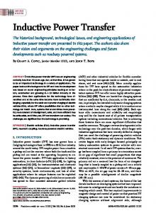
A. Transmit and Receive Circuit Analysis An inductive power link consists of a transmitting coil having inductance LT and a receiving coil LR (see Fig. 1). Some magnetic flux is shared between the coils, resulting in a coupling coefficient k, where 0 < k < 1. An ac voltage of amplitude VT is applied across the transmitting coil, and this induces an ac voltage VR on the receiving coil. The receiving coil is connected to a load RL. Thus, the power delivered to the load is given by PL =
V R2pk
(1)
2 RL
and the power drawn from the supply is PS = VSIS. The overall efficiency of the inductive link is Ș = PL/PS. Since narrowband operation is typically used, capacitors CT and CR can be used to create resonant circuits that boost the voltages across the coils. In the absence of magnetic coupling, the quality factor of the series RLC transmitting circuit is given by QT = Ȧ0LT/RT, where Ȧ0 = 1/(LTCT)1/2 = 1/(LRCR)1/2 is the frequency of oscillation and RT is a combination of the transmit coil series resistance, equivalent series resistance (ESR) of CT, and the output resistance of the power amplifier. The quality factor of the receiving circuit in the absence of a load is given by QR = Ȧ0LR/RR, where RR is a combination of the receive coil series resistance and the ESR of CR. The receiver resonant circuit can be approximated using a narrowband equivalent circuit model [see Fig. 1(b)] and assuming QR2 >> 1 so that QR2 + 1 § QR2. Using this model, we observe that when RL is added, some power will be wasted as heat due to losses in the resonant circuit. We can define the receive efficiency ȘR for the receiver circuit as
This work was supported by an NSF CAREER award ECS-0134336 and an NIH/NINDS contract HHSN265200423621C.
1-4244-0921-7/07 $25.00 © 2007 IEEE.
INDUCTIVE POWER LINK OPTIMIZATION
2080
ηR = 1+
1 RL Q R2 R R
=1−
QR′ QR
(2)
(a)
where Q'T = Ȧ0LT/(RT + RLreflect) is the quality factor of the loaded transmit circuit.
VS IS
CT
Power Amp
RT
k
+
RR
+ VT LT –
CR VR
LR
Finally we must consider the properties of the power amplifier driving the transmit coil. Like many previous designs, we use a class E amplifier to drive the coil [6]. The class E configuration requires only a single nMOS switch and has a theoretical efficiency of 100% [7]. In practice, efficiencies greater than 85% are routinely reported [8]. From equations (1) and (2) in [7], it can be shown that the peak ac voltage generated on a transmit coil powered by a class E amplifier operating from a dc supply VS is ideally
RL
–
(b) (c)
LR
RT
QR2RR
CR
RL
LTleak 1:n LTmag
2
CR
QR RR
VTpk =
RL
(d) LTleak LTmag
~LT CRreflect
VTpk
RLreflect
RLreflect
2 R RR
)|| R
ω 0 LR
V Rpk VS
L
.
(3)
Q'R is the quality factor of the receiving circuit with load. Thus, for high efficiency we should ensure that QR2RR >> RL. For high receive efficiency, Q'R will be much less than QR. The weak coupling between transmit and receive coils can be modeled as an ideal transformer, a leakage inductance LTleak = (1 – k2)LT, and a magnetizing inductance LTmag = k2LT [5]. In the weakly-coupled case where k2