Oct 16, 2012 ... XAPP792 (v1.0.1) October 16, 2012 ... and built using the 14.2 version of the
Xilinx Platform Studio (XPS) ... The complete PlanAhead, XPS, and SDK tool
project files are provided with ..... Each frame's vertical lines (1080.
Application Note: Zynq-7000 All Programmable SoC
Designing High-Performance Video Systems with the Zynq-7000 All Programmable SoC XAPP792 (v1.0.1) October 16, 2012
Summary
Author: James Lucero and Ygal Arbel
With high-end processing systems like the Xilinx Zynq™-7000 All Programmable SoC, customers want to fully utilize the processing system (PS) and custom peripherals connected to the PS within the device. An example of this is multiple video pipelines in which live video streams are written into memory (input) and memory is read to send out live video streams (output) in which the processor is accessing memory. This application note covers design principles that target customers needing high performance from the Zynq-7000 AP SoC memory interfaces, from AXI master interfaces implemented in the programmable logic (PL), and from the ARM® Cortex™-A9 processor(s). With video systems, guaranteed worst-case latency is required for the video streams to ensure that frames are not dropped or corrupted. To provide high-speed AXI master interfaces in the PL with lower latency and direct access to the Zynq-7000 AP SoC memory interfaces, connections to the high performance (HP) interfaces are required. The Zynq-7000 AP SoC contains four HP interfaces that are 64-bit or 32-bit AXI3 slave interfaces designed for high throughput. The design uses three AXI video direct memory access (VDMA) engines to simultaneously move six streams (three transmit video streams and three receive video streams), each in 1920 x 1080p format, 60 Hz refresh rate, and up to 32 data bits per pixel. Each VDMA is driven from a video test pattern generator (TPG) with a video timing controller (VTC) core to set up the necessary video timing signals. Data read by each AXI VDMA is sent to a common on-screen display (OSD) core capable of multiplexing or overlaying multiple video streams to a single output video stream. The output of the OSD core drives the HDMI video display interface on the board. Performance monitor cores are added to capture performance data. All three AXI VDMAs are connected to three separate HP interfaces by means of the AXI Interconnect and are controlled by the Cortex-A9 processor. This design uses 70% of the memory controller bandwidth. The reference system is targeted for the Zynq-7000 ZC702 evaluation board.
Included Systems
The design is created and built using the 14.2 version of the Xilinx Platform Studio (XPS) PlanAhead™ tool included with the ISE® Design Suite, System Edition. XPS helps simplify the task of instantiating, configuring, and connecting IP cores together to form complex embedded systems. The design also includes software built using the Xilinx Software Development Kit (SDK). The software runs on the Zynq-7000 AP SoC processing system and implements the control function. The complete PlanAhead, XPS, and SDK tool project files are provided with this application note to allow the designer to examine and rebuild this design or use the files as a template for starting a new design. Included with this application note is one reference system, zc702_video_3x_pipeline/, available in the ZIP file xapp792.zip.
© Copyright 2012 Xilinx, Inc. Xilinx, the Xilinx logo, Artix, ISE, Kintex, Spartan, Virtex, Vivado, Zynq, and other designated brands included herein are trademarks of Xilinx in the United States and other countries. ARM, AMBA, and CoreSight are trademarks of ARM in the EU and other countries. HDMI and High-Definition Multimedia Interface are trademarks of HDMI Licensing LLC. All other trademarks are the property of their respective owners.
XAPP792 (v1.0.1) October 16, 2012
www.xilinx.com
1
Introduction
Introduction
High-performance video systems can be created using available Xilinx AXI IP cores. The use of AXI Interconnect, AXI3 ports on the Zynq-7000 AP SoC, and AXI VDMA IP cores can form the basis of video systems capable of handling multiple video streams and multiple video frame buffers sharing a common DDR3 SDRAM memory. AXI is a standardized IP interface protocol based on the ARM AMBA4 and AMBA3 AXI specifications. The AXI interfaces used in this example design consist of AXI4, AXI3, AXI4-Lite, and AXI4-Stream interfaces as described in the AMBA4 and AMBA3 AXI specification [Ref 1]. These interfaces provide a common IP interface protocol framework for building the design. AXI Interconnect and AXI HP ports on the Zynq-7000 AP SoC together implement a high-bandwidth and high-performance memory system for use in applications where multiple devices share a common memory controller. This is a requirement in many video, embedded, and communications applications where data from multiple sources move through a common memory device, typically DDR3 SDRAM memory. AXI VDMA implements a high-performance, video-optimized DMA engine with frame buffering, scatter gather, and 2-dimensional (2D) DMA features. AXI VDMA transfers video data streams to and from memory and operates under dynamic software control or static configuration modes. The Zynq-7000 AP SoC PS supplies clocks and resets throughout the system including the PL. High-level control of the system is provided in the Zynq-7000 AP SoC PS by the Cortex-A9 processor and through the I/O peripherals (IOP), on-chip memory (OCM), and processor support IP cores. To optimize the system to balance performance and area utilization, multiple AXI interface cores are used to implement segmented/hierarchical AXI interface networks with each AXI interface core individually tuned and optimized.
Hardware Requirements
The hardware requirements for this reference system are: •
Xilinx ZC702 Rev 1 evaluation board (In JTAG mode)
•
Two USB Type-A to Mini-B 5-pin cables
•
HDMI™ cable
•
Display monitor supporting 1080p resolution (1920 x 1080 resolution at 60 frames/sec)
The installed software tool requirements for building and downloading this reference system are:
Reference System Specifics
•
PlanAhead tool, version 14.2
•
Platform Studio 14.2
•
ISE Design Suite 14.2
•
SDK 14.2
The reference system includes the Zynq-7000 AP SoC PS, AXI_INTERCONNECT, clock generator, AXI_VTC, AXI_TPG, AXI_VDMA, AXI_PERF_MON, AXI_OSD, and HDMI interface cores. The processor(s) or DMA controller (DMAC) in the Zynq-7000 AP SoC PS can access AXI slave interfaces in the PL by means of the AXI general-purpose (GP) interfaces, which are 32-bit AXI3 master interfaces. The S_AXI_GPx interfaces are considered lower performance interfaces compared to S_AXI_HPx interfaces and are not used in this design. This design uses only one AXI GP interface (M_AXI_GP0) for slave registers in the design.
XAPP792 (v1.0.1) October 16, 2012
www.xilinx.com
2
Reference System Specifics Figure 1 shows a block diagram of the reference system. X-Ref Target - Figure 1
I/O Peripherals
MIO
USB
Processing System Clock Generation
USB
2x USB
GigE GigE SD SDIO SD SDIO GPIO UART UART CAN CAN I2C I2C SPI SPI
2x GigE
Reset
Application Processor Unit
SWDT TTC
2x SD IRQ
ARM Cortex-A9 CPU
MMU
System Level Control Registers
32 KB I-Cache
ARM Cortex-A9 CPU
MMU
32 KB D-Cache
32 KB D-Cache
32 KB I-Cache
Snoop Controller, AWDT, Timer
GIC DMA 8 Channel
512 KB L2 Cache & Controller
OCM Interconnect
256K SRAM Memory Interfaces
Central Interconnect CoreSight Components
Memory Interfaces SRAM/ NOR
DDR2/3, LPDDR2 Controller
DAP
ONFI 1.0 NAND
DevC
Programmable Logic to Memory Interconnect
Config AES/ SHA
High-Performance Ports
Q-SPI CTRL
EMIO
FPU and NEON Engine
FPU and NEON Engine
General-Purpose Ports
XADC 12 bit ADC
DMA Sync
IRQ
ACP
Programmable Logic HP0
HP1
HP2
AXI AXI AXI VDMA VDMA VDMA
AXI OSD
FSYNC
AXI VTC
AXI TPG
AXI PERF MON
AXI TPG
HDMI
AXI TPG
GP0
XAPP792_01_100912
Figure 1:
Reference System Block Diagram
Note: The block diagram in Figure 1 doesn’t show VFBC to AXI Stream blocks. Table 1 shows the address map of the system. Table 1: Reference System Address Map Peripheral
Instance
Base Address
High Address
processing_system7
eps7_0 (M_AXI_GP0)
0x40000000
0x7FFFFFFF
processing_system7
eps7_0 (S_AXI_HP0)
0x00000000
0x3FFFFFFF
processing_system7
eps7_0 (S_AXI_HP1)
0x00000000
0x3FFFFFFF
processing_system7
eps7_0 (S_AXI_HP2)
0x00000000
0x3FFFFFFF
axi_vtc
axi_vtc_0
0x53800000
0x5380FFFF
axi_osd
osd_0
0x43A00000
0x43A0FFFF
XAPP792 (v1.0.1) October 16, 2012
www.xilinx.com
3
Hardware System Specifics Table 1: Reference System Address Map (Cont’d) Peripheral
Hardware System Specifics
Instance
Base Address
High Address
axi_tpg
axi_tpg_0
0x5EE00000
0x5EE0FFFF
axi_vdma
axi_vdma_0
0x40000000
0x4000FFFF
axi_tpg
axi_tpg_1
0x5EE10000
0x5EE1FFFF
axi_vdma
axi_vdma_1
0x40010000
0x4001FFFF
axi_tpg
axi_tpg_2
0x5EE20000
0x5EE2FFFF
axi_vdma
axi_vdma_2
0x40020000
0x4002FFFF
axi_perf_mon
perf_axi_mon_0
0x41000000
0x4100FFFF
This section describes the high-level features of the reference design, including how to configure the main IP cores and the Zynq-7000 AP SoC PS. Information about useful IP features, performance and area trade-offs, and other configuration information is also provided. This information is applied to a video system, but the principles used to optimize the system performance are applicable to a wide range of high-performance AXI interface-based designs. For information about AXI system optimization and design trade-offs, see Xilinx AXI Reference Guide (UG761). This application note assumes the designer has general knowledge of the Zynq-7000 AP SoC platform, AXI protocol, and the PlanAhead and XPS tools. See EDK Concepts, Tools, and Techniques: A Hands-On Guide to Effective Embedded System Design (UG683) for more information about the XPS tools.
Zynq-7000 AP SoC PS The Zynq-7000 AP SoC PS is configured to use one Cortex-A9 processor, one IIC (MIO interface), one UART (MIO interface) and the Zynq-7000 AP SoC memory interfaces (AXI3 interfaces). These are enabled by the first stage boot loader (FSBL) created by the SDK tool. The Zynq-7000 AP SoC PS provides clock and reset signals to both the PS and PL. See Table 2 for the clock signal frequencies used in this design. Table 2: Reference System Clock Frequencies Element
Clock Frequency (MHz)
Processor
666
32-bit DDR3 memory controller
533
High-speed AXI interfaces (S_AXI_HP0, S_AXI_HP1, S_AXI_HP2)
150
Low-speed AXI interfaces (M_AXI_GP0)
75
64-bit Memory Interconnect
355
32-bit Master and Slave Interconnect
222
Refer to Zynq-7000 EPP Technical Reference Manual (UG585) for more information about clock frequencies and interconnects in the Zynq-7000 AP SoC PS.
Video Related IP Cores The reference design implements three video pipelines running at 1080P60 (1920 x 1080 frames at 60 frames/sec). Each frame consists of 4 bytes per pixel to represent an upper-bound, high-quality video stream such as RGBA or YUV 4:4:4 with alpha channel information. Each video pipeline requires a bandwidth of 497.6 MB/s, which is approximately 4 Gb/s.
XAPP792 (v1.0.1) October 16, 2012
www.xilinx.com
4
Hardware System Specifics The video traffic is generated by TPG IP cores and displayed by the OSD core. The total aggregate read/write bandwidth generated is equivalent to six video streams, requiring nearly 3 GB/s (24 Gb/s). This application note demonstrates AXI system performance using six high-definition video streams. At a minimum, video systems must include a source, some internal processing, and a destination. There can be multiple stages internally using a variety of IP modules. The canonical video system is illustrated in Figure 2 to show that most video systems consist of input, pre-processing, main processing, post-processing and output stages. Many of the video stages illustrated require memory access at video rates. Video data is transferred into and out of memory according to the requirements of internal processing stages. In this application note, the internal block memory traffic is created by a series of test pattern generators to simulate typical conditions. X-Ref Target - Figure 2
Source
I/O Interface
Line Buffers
Line Buffers
Line Buffers
Pre Processing
Core Processing
Post Processing
Frame Buffers
Frame Buffers
Frame Buffers
I/O Interface
CPU/Controller
External Memory X792_02_091312
Figure 2:
Typical Video System
AXI Interconnect (AXI_INTERCONNECT_GP0_MASTER) Instance The AXI_INTERCONNECT_GP0_MASTER instance is optimized for area by using the shared bus topology which allows the Zynq-7000 AP SoC PS to access slave registers. The Cortex-A9 processor writes and reads all AXI4-Lite slave registers in the design for control and status information. In addition, this portion of the design is clocked at 75 MHz, which is a slower clock rate compared to the rest of the system. The AXI interface slaves are for three instances of AXI_VDMA slave interfaces, AXI_VTC, AXI_PERF_MON, three instances AXI_TPG, and AXI_OSD.
AXI Interconnect (AXI_INTERCONNECT_HPx_SLAVE) Instances The AXI_INTERCONNECT_HP0_SLAVE, AXI_INTERCONNECT_HP1_SLAVE, and AXI_INTERCONNECT_HP2_SLAVE instances are used for high-speed masters and slaves, which include high-throughput and high FMAX optimizations. The connectivity mode is set to crossbar mode to accommodate high throughput. These instances provide the highest FMAX and throughput for the design by having a 64-bit core data width and running at 150 MHz. Each instance connects one AXI VDMA (AXI MM2S and AXI S2MM Master interfaces) to one HP interface. Refer to AXI VDMA Instances and Zynq-7000 AP SoC Memory Controller, page 6 for AXI interface settings to achieve high performance for masters and slaves.
AXI VDMA Instances The AXI VDMA core is designed to provide video read and write transfer capabilities from the AXI4 memory-mapped domain to AXI4-Stream, and vice versa. The AXI VDMA core provides high-speed data movement between system memory and AXI4-Stream-based target Video IP cores. AXI4 memory-mapped interfaces are used for high-speed data movement and buffer
XAPP792 (v1.0.1) October 16, 2012
www.xilinx.com
5
Hardware System Specifics description fetches across the AXI interface. With this design, register direct mode is used for the buffer descriptors that eliminate the need for the SG interface in the system. The design incorporates video-specific functionality such as genlock and Frame Sync for fully synchronized frame DMA operations as well as two-dimensional DMA transfers. In addition to synchronization, frame store numbers and scatter/gather or register direct mode operations are available for ease of control by the central processor. In this design, three instances of AXI VDMA are used with the AXI4 MM2S interface, AXI4 S2MM interface, AXI4-Stream MM2S interface, and AXI4-Stream S2MM interface. In addition, with each instance the initialization, status, and management registers are accessed through an AXI4-Lite slave interface. The 32-bit wide AXI MM2S and AXI S2MM interfaces from the AXI VDMA instances are connected to the AXI_INTERCONNECT_HPx_SLAVE instances. The AXI4-Stream interfaces are clocked at 148.5 MHz, which requires enabling the C_PRMRY_IS_ACLK_ASYNC parameter in the IP core. The AXI VDMA masters are clocked at 150 MHz, which does not require clock converters to the 150 MHz AXI interface core frequency. However, protocol converters and upsizers are required in the AXI interface to convert 32-bit AXI4 protocol to 64-bit AXI3 protocol. AXI VDMA instances are set for a maximum burst of 32. The AXI3 protocol only supports a maximum burst of 16. However, because the connected HP interface on the Zynq-7000 device is 64 bits, this interface supports a transfer size of 64 bits x 16 data beats (32 bits x 32 data beats). In addition, line buffers inside the AXI VDMA for the read and write sides are set to accommodate one line which is 8 KB deep (1920 x 4 bytes = 7680 bytes deep). For AXI interface settings for AXI VDMA, the master interfaces have a read and write issuance of 2 to provide a moderate amount of transactions to the Zynq-7000 device, a read and write FIFO depth of 512, and store and forward enabled to improve system performance and reduce the risk of system throttling. In addition, FULLY_REGISTERED mode is enabled on the AXI master interfaces to assist with meeting timing at 150 MHz. These settings also follow performance recommendations for AXI endpoint masters as described in Xilinx AXI Reference Guide (UG761).
Zynq-7000 AP SoC Memory Controller Overview The Zynq-7000 AP SoC memory controller on the ZC702 board is a 32-bit DDR3 controller clocked at 533 MHz. The addressing method used is row, bank, column. The memory controller register settings are automatically set by the FSBL. The memory controller has four direct connections which are from the AXI_HP to DDR interface (two connections), from the central interconnect, and from the L2 cache interface in the Zynq-7000 device. In addition, the Quality of Service (QoS) Priority module is positioned between these four sources and the connections to the memory controller, which enables regulation of traffic patterns by limiting requests. The HP0/HP1 and HP2/HP3 slave interfaces share direct connections to the memory controller by means of an AXI_HP to DDR interface. With this design, HP0/HP1/HP2 slave interfaces are used. For more information about these interfaces, refer to Zynq-7000 EPP Technical Reference Manual (UG585). Each HP slave interface is 64 bits, has a read/write acceptance of 8, and FIFOs are already built inside the HP interfaces. FULLY_REGISTERED mode is enabled to ensure the interface meets timing at 150 MHz. These settings help ensure a high degree of transaction pipelining is active to improve system throughput. Achieving over 60% Utilization To achieve optimal utilization of the memory controller, transactions from the master interfaces need to occur in different banks and must be aligned to KB/MB boundaries. With video designs,
XAPP792 (v1.0.1) October 16, 2012
www.xilinx.com
6
Hardware System Specifics frame buffers need to be accessed in different banks, and the overlapping of banks must be minimized while the video design is running. This design demonstrates 1080P60 (1920 x 1080) with four bytes per pixel. Each horizontal line is about 8 KB (1920 x 4 = 7680), so the AXI VDMA line stride is set to 8 KB boundaries. The start of every new line is aligned on an 8 KB boundary. Each frame’s vertical lines (1080 lines per frame) are aligned to a 2 KB boundary for each frame. Therefore, each frame buffer in this design is aligned on 16 MB boundaries (8 KB x 2 KB). With multiple video pipelines, N video devices are accessing N frame buffers using identical timing. Assuming 16 MB frame buffers, this means that nearly simultaneous access requests from different video devices have nearly identical addresses [23:0]. Because in the default address mapping, the bank select address is on bits [14:12], they are also identical addresses. Therefore, requests access the same bank but from different pages, causing a full page miss overhead (precharge-activate-read/write) each time. This can cause very low DRAM efficiency (in the 40–50% range). The memory controller on the ZC702 board is configured for row (13 bits), bank (3 bits), column (10 bits), and word selection (2 bits) using this DDR address configuration: DDR_ADDR[27:15]
Row
DDR_ADDR[14:12]
Bank
DDR_ADDR[11:0]
Column/Word
The AXI master address is reordered to ensure that each frame buffer is in its own bank. Because each frame buffer is aligned on 16 MB boundaries, it takes 24 bits to represent the address space [23:0] and three bits to represent the bank [26:24]. AXI address bits [26:24] are moved to [14:12] for the DDR address. The reordered AXI master address looks like: axi_addr[31:27] axi_addr[23:12] axi_addr[26:24] axi_addr[11:0] An additional EDK IP core was created for this application note to reorder the AXI master address to the AXI interface. With this reordering, the processor or software must handle the address reordering. Note: This IP core is only an example for this application note. Frame Buffers With each AXI VDMA in normal genlock mode, two frame buffers are active at one time and are usually delayed by one frame buffer (i.e., read/write operations are not occurring in the same frame buffer). To create a deterministic traffic pattern in this design, all AXI VDMA interfaces share the same FSYNC signal. This design uses a total of nine frame buffers, but the memory controller only has eight banks. Because only six frame buffers are active at one time in this design, the frame buffer locations must be carefully chosen to limit or eliminate bank overlaps. Table 3 shows the frame buffer’s base addresses. BANK5 is chosen for AXI VDMA1 FRAME2 and AXI VDMA2 FRAME0. The potential for bank overlaps is minimized by placing the shared banks on FRAME0 and FRAME2 (opposite ends of the frame buffers) because the design shares the same FSYNC signal, and frame pointers are increased sequentially. Table 3: Frame Buffer Base Addresses Frame Buffer
Base Address
Bank Number
AXI VDMA0
XAPP792 (v1.0.1) October 16, 2012
FRAME0
0x08000000
BANK0
FRAME1
0x09000000
BANK1
FRAME2
0x0A000000
BANK2
www.xilinx.com
7
Hardware System Specifics Table 3: Frame Buffer Base Addresses Frame Buffer
Base Address
Bank Number
AXI VDMA1 FRAME0
0x0B000000
BANK3
FRAME1
0x0C000000
BANK4
FRAME2
0x0D000000
BANK5
AXI VDMA2 FRAME0
0x1D000000
BANK5
FRAME1
0x1E000000
BANK6
FRAME2
0x1F000000
BANK7
QoS The QoS control mechanism allows the control of requests from interfaces to the memory controller by setting the maximum number of outstanding transactions, peak rates, average rate, and burst level. This is beneficial especially when video pipelines are used and cannot be throttled. This design does not use the QoS feature because the processor traffic does not throttle the video pipelines.
AXI VTC The AXI VTC core is a general-purpose video timing generator and detector. The input side of this core automatically detects horizontal and vertical synchronization pulses, polarity, blanking, timing, and active video pixels. The output side of the core generates the horizontal and vertical blanking and synchronization pulses used in a standard video system, including support for programmable pulse polarity. The AXI VTC contains an AXI4-Lite Interface to access slave registers from a processor. For more information about the AXI VTC, refer to LogiCORE IP Video Timing Controller (DS857). In this design, two AXI VTC instances are used with detection disabled. The first instance corresponds to the video input portion of the video pipelines while the second corresponds to the AXI OSD, which forms the read portion of the video pipelines. The VTC v3.0 core is provided under license and can be generated using the CORE Generator™ tool.
AXI TPG The AXI TPG core contains an AXI4-Lite Interface to access slave control registers from a processor. In this design, the video traffic to DRAM is generated by a series of TPGs. Each TPG core is capable of generating several video test patterns that are commonly used in the video industry for verification and testing. Here, the TPG is used as a replacement for other video IP because the emphasis is on the amount of traffic generated to demonstrate the performance of the system. The control software demonstrates generation of color bars, horizontal and vertical burst patterns, and the generation of zoneplates. No matter which test pattern is chosen, the amount of data generated is the same, namely, 1080P60 HD video (1920 x 1080 frames at 60 frames/second). For example, a YUVA444 1080P60 pattern generates 497.7 MB/s, which is nearly a 4 Gb/s data stream. Several operating modes are accessible through software control. For the purposes of this application note, the TPG always generates a test pattern which could be one of color bars, horizontal frequency sweep, vertical frequency sweep, or zoneplate patterns. These patterns are meant for testing purposes only and are not calibrated to broadcast industry standards. XAPP792 (v1.0.1) October 16, 2012
www.xilinx.com
8
Hardware System Specifics
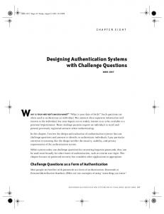
AXI OSD The AXI OSD core provides flexible video processing for alpha blending and compositing of up to 8 independent layers. The OSD core also provides simple text and graphics generation and is capable of handling images up to 4K by 4K pixels, in YUVA 4:4:4 or RGBA image formats, and in 8, 10, or 12 bits per color component. In this application note, the OSD core is used to blend the five video streams as separate layers for display. As the video streams generated by the TPG cores are enabled through software control, the display shows the blended layers on top of each other. Figure 3 shows a top-level block diagram of the OSD core. X-Ref Target - Figure 3
FIFO Input (Layer 0)
FIFO Input (Layer 1)
Graphics Controller (Layer 2)
Host Control
Control Registers
Priority Select
Priority 0 Multiplexer (Lowest)
Priority 1 Multiplexer
Priority 2 Multiplexer (Highest)
Background Color
Alpha Blend Element
Alpha Blend Element
Alpha Blend Element
Video Data Out
Alpha Blend Pipeline Position Screen Size
Host Status
Interrupt Status
Alpha Blend Control
Alpha Blend Control
Alpha Blend Control
H/V Counters X792_03_091312
Figure 3:
Example 3-layer OSD Block Diagram
The AXI OSD core contains an AXI4-Lite interface to access the slave registers from a processor. For more information about the AXI OSD core, see LogiCORE IP Video On-Screen Display (DS837). The Xilinx Video On-Screen Display core is provided under the SignOnce IP site license and can be generated using the CORE Generator tool. A simulation evaluation license for the core is also available. To access the full functionality of the core, including FPGA bitstream generation, a full license must be obtained from Xilinx.
XAPP792 (v1.0.1) October 16, 2012
www.xilinx.com
9
Software Applications
AXI_PERF_MON The AXI_PERF_MON core allows up to eight AXI interfaces to measure bus latency with different metrics. Two counters are used in this design, which provide read and write byte counts using the metric counter registers. This design incorporates three bus monitor interfaces. The AXI_S_HP0, AXI_S_HP1, and AXI_S_HP2 slave interfaces are individually monitored. The Sample Interval register (number of clocks) is set to count for two seconds. During this time, the AXI_PERF_MON core monitors read bytes and write bytes on the AXI interface during the two second interval and writes these values into the Metric Counter registers after the Sample Interval counter has overflowed. A software routine polls the Sample Interval counter interrupt bit to determine when the two second interval is complete. For more information about the AXI_PERF_MON core, refer to LogiCORE IP AXI Performance Monitor (PG037).
Software Applications
AXI VDMA Display Application This software application starts up the video pipelines and can display separate layers or alpha blend all layers on the LCD screen while allowing real-time bandwidth examination. The software application is run from the OCM in the Zynq-7000 AP SoC PS. Application-level software for Xilinx Video IP cores is written in the C language using the drivers provided for each IP core. The programmer’s model for each core describes the particular API used by the drivers. Alternately, application software can be written to use the IP core registers directly and handle the interrupts at the application level, but using the provided drivers and a layer of control at the application level is a far more convenient option. The software application performs these steps: 1. Configures the HDMI port for 1080P60 output on the ZC702 board through the IIC interface. 2. The TPG instances are set to write a default gray pattern that starts after the AXI VTC instances are started. 3. The AXI VDMA instances are started, which consists of the processor writing the buffer descriptors to registers in the AXI VDMA. The program then starts the read channel, and then the write channel that initiates the transfers for the VDMA instances. 4. The AXI VTC instances are started with a 1080P60 timing configuration. 5. The AXI OSD instance is configured for 1080P output. 6. The three TPG instances in the design are configured to write color bars (layer 0), zone plate patterns (layer 1), and a vertical sweep (layer 2). After the initial setup sequence, a specific layer can be displayed by selecting a numbered option (options 0–3). When the number of a particular layer is selected, the OSD registers are modified to make the alpha blending on that particular layer the highest value while the other layers have the lowest value. When alpha blending all layers (option 3), different values are given to the alpha blending register for each layer to show all layers on the LCD screen at once. Option 4 provides a 32-bit memory test to the DDR3 memory. Option 5 sets up the performance monitoring IP instance to measure read byte counts and write byte counts on a single AXI Interface at one time. A software function is used to present the TX and RX throughput number for each AXI VDMA instance as well as the system throughput number on a host PC terminal display.
XAPP792 (v1.0.1) October 16, 2012
www.xilinx.com
10
Executing the Reference System in Hardware
Executing the Reference System in Hardware
A ZC702 board is prepared using these steps: 1. Connect a USB cable from the host PC to the USB JTAG port of the ZC702 board. Ensure the appropriate device drivers are installed. 2. Connect a second USB cable from the host PC to the USB UART port of the ZC702 board. Ensure that the USB-UART drivers have been installed. 3. Connect the ZC702 HDMI connector to a video monitor capable of displaying a 1920 x 1080p, 60 Hz video signal. 4. Connect the power supply cable to the ZC702 board. 5. Apply power to the ZC702 board. 6. Start a terminal program such as HyperTerminal on the host PC with these settings: •
Baud Rate: 115200
•
Data Bits: 8
•
Parity: None
•
Stop Bits: 1
•
Flow Control: None
Executing the Reference System using the Pre-Built Bitstream and the Compiled Software Application To execute the system using files in the /zc702_video_3x_pipeline/ready_for_download directory, follow these steps: 1. In a command shell or terminal window, change directories to the ready_for_download directory: % cd /zc702_video_3x_pipeline/ready_for_download 2. Run the design with the following XMD command using the TCL script that downloads the bitstream to the board, connects to the processor, downloads and runs the FSBL, and downloads and runs the software application: % xmd –tcl xmd_top.tcl
Results from Running Hardware and Software
A color bar pattern should now be visible on the LCD monitor connected to the ZC702 board, and the host PC terminal program should display the output shown in Figure 4. X-Ref Target - Figure 4
X792_04_091312
Figure 4:
XAPP792 (v1.0.1) October 16, 2012
www.xilinx.com
HyperTerminal Output
11
Performance The application menu on the terminal screen has six options:
Performance
•
0: Shows the colorbar layer on the LCD display
•
1: Shows the zone plate layer
•
2: Shows the vertical sweep layer
•
3: Shows an alpha blend of all three layers at the same time
•
4: 32-bit memory test executed in the DDR3 memory
•
5: Terminal shows real-time system performance parameters (one second of transfers)
The DDR3 PHY is set for 32 bits with a memory clock frequency of 533 MHz (1066 MHz data rate). The theoretical throughput on DDR3 is 4.2 GB/s which is the total bandwidth available in the design. Selecting option 5 of the software application produces this output: AXI_VDMA0 Tx = 497.670340 MB/s AXI_VDMA0 Rx = 497.670372 MB/s AXI_VDMA1 Tx = 497.670888 MB/s AXI_VDMA1 Rx = 497.670836 MB/s AXI_VDMA2 Tx = 497.670400 MB/s AXI_VDMA2 Rx = 497.670384 MB/s System Total Bandwidth = 2986.023220 MB/s DDR3 Theoretical Bandwidth = 4266.666666 MB/s Percent of DDR3 Theoretical Bandwidth = 69.984919%
Note: The numbers can vary slightly from these values. Total bandwidth is approximately 2986 MB/s out of 4267 MB/s, which is approximately 70% of the total bandwidth of the main memory.
Building Hardware
This section covers rebuilding the hardware design. Before rebuilding the project, the user must ensure that the licenses for AXI OSD and AXI VTC cores are installed. To obtain evaluation licenses for the AXI VTC or AXI OSD core, the user should visit these web pages and click evaluate: http://www.xilinx.com/products/intellectual-property/EF-DI-VID-TIMING.htm http://www.xilinx.com/products/intellectual-property/EF-DI-OSD.htm Note: The generated bitstream is located at: /zc702_video_3x_pipeline/PA/impl_1/system.bit
1. Open the zc702_video_3x_pipeline/PA/pa_project.ppr file with the PlanAhead tool. 2. In the Design Runs tab, right-click impl_1 and click Generate Bitstream. 3. Click Yes to the No Implementation Results Available dialog. The Launch Run Critical Messages dialog appears showing two constraints not found. This is a known issue. Click OK. 4. Export using the Hardware for SDK option by selecting File > Export > Export Hardware for SDK… 5. Export to . Be sure to check Include Bitstream and Export Hardware. Click OK.
XAPP792 (v1.0.1) October 16, 2012
www.xilinx.com
12
Compiling Software and Running Design Through the SDK Tool
Compiling Software and Running Design Through the SDK Tool
Compiling Software with the SDK Tool 1. Start the SDK tool. In Linux, type xsdk. 2. In the Workspace Launcher, select this workspace: /zc702_video_3x_pipeline/SW/SDK_Workspace 3. Click OK. 4. To set the repository, click Xilinx Tools > Repositories. a. For Local Repositories click New.... b.
Change directories to: /zc702_video_3x_pipeline/SW/repository
c.
Click OK.
5. The Board Support Package (BSP), hardware platform, and software applications must be imported. Click File > Import > General > Existing Projects into Workspace. 6. Click Next and browse to the /zc702_video_3x_pipeline/SW directory. Click OK. 7. Make sure that all check boxes are selected, including axi_vdma_display, hw_platform_0, standalone_bsp_0, and zynq_fsbl_0. Click Finish. Note: The BSP and software applications are compiled. This should take 2–5 minutes. If the axi_vdma_display software application contains build errors, right-click axi_vdma_display in the Project Explorer tab and select Change Referenced BSP, then select standalone_bsp_0.
8. At this point, existing software applications can be modified, and new software applications can be created with the SDK tool.
Running the Hardware and Software Through the SDK Tool 1. Click Xilinx Tools > Program FPGA. 2. Click Program. 3. In the Project Explorer window, right-click axi_vdma_display > Run As > Launch on Hardware. By default, the SDK tool runs the FSBL using a TCL script.
Reference Design
The reference design can be downloaded from: https://secure.xilinx.com/webreg/clickthrough.do?cid=192742 Table 4 shows the reference design checklist. Table 4: Reference Design Checklist Parameter
Description
General Developer name
James Lucero and Ygal Arbel
Target devices (stepping level, ES, production, speed grades)
Zynq-7000 AP SoC (ES)
Source code provided
Y
Source code format
VHDL, Verilog (some sources encrypted)
Design uses code/IP from existing Xilinx application note/reference designs, CORE Generator tool, or 3rd-party reference designs provided for EDK and video cores generated from the CORE Generator tool
Y
XAPP792 (v1.0.1) October 16, 2012
www.xilinx.com
13
References Table 4: Reference Design Checklist (Cont’d) Parameter
Description
Simulation Functional simulation performed
N/A—Simulation not supported
Timing simulation performed
N/A—Simulation not supported
Testbench used for functional and timing simulations
N/A—Simulation not supported
Testbench format
N/A—Simulation not supported
Simulator software/version used
N/A—Simulation not supported
SPICE/IBIS simulations
N/A—Simulation not supported
Implementation Synthesis software tools/version used
XST 14.2
Implementation software tools/versions used
ISE Design Suite 14.2: System Edition
Static timing analysis performed
Y (passing timing in PAR/TRCE)
Hardware Verification Hardware verified
Y
Hardware platform used for verification
ZC702 board
Table 5 shows the device utilization in the reference design. Table 5: Device Utilization Item
References
Value
Device
XC7Z020
Device Speed
-1
Grade Package
CLG484
Registers
32,739
Occupied Slices
10,452
Slice LUTs
22,686
I/Os
22
RAMB36E1s
24
RAMB18E1s
12
1. AMBA AXI4-Stream Protocol Specification 2. UG683, EDK Concepts, Tools, and Techniques: A Hands-On Guide to Effective Embedded System Design 3. DS768, LogiCORE IP AXI Interconnect 4. UG111, Embedded System Tools Reference Manual 5. UG761, Xilinx AXI Reference Guide 6. DS799, LogiCORE IP AXI Video Direct Memory Access 7. DS837, LogiCORE IP Video On-Screen Display 8. DS857, LogiCORE IP Video Timing Controller
XAPP792 (v1.0.1) October 16, 2012
www.xilinx.com
14
Revision History 9. PG037, LogiCORE IP AXI Performance Monitor 10. UG585, Zynq-7000 EPP Technical Reference Manual
Revision History
Notice of Disclaimer
The following table shows the revision history for this document. Date
Version
10/12/12
1.0
10/16/12
1.0.1
Description of Revisions Initial Xilinx release. Removed conditional text banner.
The information disclosed to you hereunder (the “Materials”) is provided solely for the selection and use of Xilinx products. To the maximum extent permitted by applicable law: (1) Materials are made available "AS IS" and with all faults, Xilinx hereby DISCLAIMS ALL WARRANTIES AND CONDITIONS, EXPRESS, IMPLIED, OR STATUTORY, INCLUDING BUT NOT LIMITED TO WARRANTIES OF MERCHANTABILITY, NON-INFRINGEMENT, OR FITNESS FOR ANY PARTICULAR PURPOSE; and (2) Xilinx shall not be liable (whether in contract or tort, including negligence, or under any other theory of liability) for any loss or damage of any kind or nature related to, arising under, or in connection with, the Materials (including your use of the Materials), including for any direct, indirect, special, incidental, or consequential loss or damage (including loss of data, profits, goodwill, or any type of loss or damage suffered as a result of any action brought by a third party) even if such damage or loss was reasonably foreseeable or Xilinx had been advised of the possibility of the same. Xilinx assumes no obligation to correct any errors contained in the Materials or to notify you of updates to the Materials or to product specifications. You may not reproduce, modify, distribute, or publicly display the Materials without prior written consent. Certain products are subject to the terms and conditions of the Limited Warranties which can be viewed at http://www.xilinx.com/warranty.htm; IP cores may be subject to warranty and support terms contained in a license issued to you by Xilinx. Xilinx products are not designed or intended to be fail-safe or for use in any application requiring fail-safe performance; you assume sole risk and liability for use of Xilinx products in Critical Applications: http://www.xilinx.com/warranty.htm#critapps.
XAPP792 (v1.0.1) October 16, 2012
www.xilinx.com
15