Today, network and content providers are required to cooperate with Law .... The goal of the Cisco architecture is to provide LI system that is compliant to the valid ..... and one for CC (4), one Delivery Function for each LEMF and each type of ...
Designing Lawful Interception in IPv6 Networks Libor Polčák, Matěj Grégr, Michal Kajan, Petr Matoušek, Vladimír Veselý {ipolcak,igregr,ikajan,matousp,ivesely}@fit.vutbr.cz Brno University of Technology Faculty of Information Technology Božetěchova 2, 612 66 Brno, Czech Republic
Abstract The aim of this paper is to enumerate major issues in designing a lawful interception system for IPv6 networks. Today, network and content providers are required to cooperate with Law Enforcement Agencies (LEAs) in order to provide a lawful interception (LI) similarly as it is required from telecommunication operators. LI in IP networks is not as easy as in telecommunications. One major challenge is the identification of a tracked person. IPv6 brings new challenges, e.g. a support of temporary IP addresses, privacy extension or default IPv6 tunnels. There are LI implementation recommendations given by US law (Communications Assistance for Law Enforcement Act – CALEA) or EU standards (defined by European Telecommunications Standards Institute – ETSI). Nevertheless, these documents do not cover IPv6 networks. This paper overviews related documents and current state-of-the-art. Then, it identifies issues of IPv6 LI and proposes possible approach to user’s identity detection, and other issues related to IPv6 LI deployment – enhancement of privacy of users in small networks, issues of multicast traffic and IPv6 transition mechanisms. Finally, this paper shows an architectural design of the system based on ETSI standard and describes how ETSI functions blocks are designed. It also describes some basic considerations and issues when implementing proposed architecture. Proposed architecture is mapped onto network devices. Suggested deployment of the system allows for the scalability of eavesdropping with respect to identified issues.
Keywords: lawful interception, IPv6, networking user identity, communication tracking. 1 Introduction Lawful interception (LI) is a security process in which a service provider or a network operator collects and provides law enforcement officials with intercepted communications of private individuals or organizations. In Europe, LI implementation is required by the EU International User Requirement 19951 that allows LI to prevent crime, including fraud and terrorism. Service providers are obliged to comply with LI standards and provide traffic monitoring and recording required by a security body called Law Enforcement Agency (LEA). Monitoring architecture, standards for communication with LEA and responsibility of network providers are specified in standards ETSI TS 102 232-(1-5) [1], [2], [3], [4], [5] approved by ETSI. The service is well implemented in traditional telephony (PSTN) within the telecommunication network infrastructure based on circuit switching. Internet is a packet based network and its communication proceeds on different layers of OSI model. Header information of a packet transmitted over internet can change as the packet moves from one network to another, especially on L2 and L3 layers. This makes LI and namely determination of the target identification a crucial issue. Comparing to traditional telephony, target identity cannot be precisely determined by single information from a data flow, but further data and their analysis is required (DHCP logs, Radius logs, etc.). Another issue is a point of interception since target and non-target transmissions are often transferred interleaved; consequently, separation of applications and relevant data is not a trivial matter. That activity requires sophisticated methods and significant computing power. In packet networks, packets of one flow can also be transported over different routes. In addition, communication channels can be encrypted on application level which makes LI extremely difficult if not impossible. LI in IPv4 networks was mainly built on the fact that IPv4 address is a unique identifier of the target, mostly of a network interface of a computer connected to the network. Additional application-level information can be used to make the identification more precise, especially email addresses, login names, etc. Today, the protocol IPv6 comes to be deployed in a large scale. This brings new issues and challenges in the area of lawful interception.
An IPv6 address is not a unique identifier of a host because of utilisation of temporary addresses, link local addresses, privacy extension, etc. Migration from IPv4 to IPv6 is also connected with deployment of several types of tunnelling mechanism that provide IPv6 connection over IPv4 infrastructure. Tunnels can be misused to bypass LI monitoring points. All these aspects have raised new challenges for network providers that have to match lawful requirements and regulations over their networks. This paper deals with the issue of lawful interception in IPv6 networks. It identifies main issues of IPv6 that makes LI more complicated and shows how these issues can be settled in order to make LI in IPv6 networks possible. The paper proposes a system architecture for LI in IPv6 and discusses basic components of the system including their relation to ETSI standards and recommendations. The structure of the document is as follows. The second section makes a survey of current work and known approaches. It also gives an overview of ETSI standards related to this work. The third section discusses IPv6 challenges in LI monitoring. Special attention is given to user identification. It shows what kind of network data and services can be used to properly identify a user on IPv6 networks, either in end-networks using L2 information, or on backbones from L3 information. The main part of the document consisting of section 4 introduces the proposed architecture of a system for lawful interception in IPv6 networks. It describes basic building blocks and their functionality. It also shows how intercepted data are collected and pre-processed for further analysis. Section 5 shows a scenario how the system can be deployed. We conclude the paper in section 6 with comments on the current development status of the considered LI system.
2 Current State and Related Work Originally, LI was performed inside telecommunication networks. In 1990s voice transmission over the Internet became possible and LEAs started to call for laws concerning interception within IP networks. In the USA, network and service providers are required to cooperate with LEAs by Communications Assistance for Law Enforcement Act (CALEA). ETSI introduced European recommendations for LI in ETSI TR 101 943 [6]. Requirements of both American and European LIs are very similar. Generally, the LI system should be able to provide LEA signalling information about perceived communication. LEA may additionally request whole communication context. A few commercial companies have introduced their solutions for LI. Commercial companies usually do not release specification of their LI systems for public. However, Cisco describes architecture of its LI system in RFC 3924 [7]. The goal of the Cisco architecture is to provide LI system that is compliant to the valid laws in different countries. Aqsacom based its LI system on ETSI recommendations and also provides general architecture of its system [8]. The existing LI documents are based on the IPv4. Nowadays, IPv6 begins to replace IPv4. Huge address space is not the only novelty of IPv6 compared to IPv4. Usually, one IPv4 address is assigned per computer's interface. IPv6 allows more than one IPv6 address to be used for communication at the same time. IPv4 address assignment is typically managed by network provider. ETSI recommendations on LI propose analysis of Radius communication (in RFC 2865 [9]) to learn an IP address of the suspect. A computer using IPv6 is ordinarily able to communicate with an address previously unknown to its network provider (modified EUI-64 in RFC 4291 [10], privacy extension in RFC 4941 [11]). Mobility issues of IPv6 networks have already been described by Rojas et al. [12]. The paper focuses on movement prediction and minimising the configuration of the intercepting probes in the network. Our work analyses issues more fundamental in IPv6 networks, i.e. issues that occur also inside immobile networks. Colitti et al. [13] describe IPv6 tunnelling methods and tunnel detection. Tunnel detection is the basic step for LI system. Identification of the traffic is the following step. National Institute of Standard and Technology (NIST) published [14] guidelines how to deploy secure IPv6 networks. The guide warns network administrators that ignoring IPv6 in a network configuration does not mean that IPv6 over IPv4 would not appear. We follow the recommendations and apply them in the LI context. Our tunnel detection is partially based on the guidelines. Cronin et al. [15] studied reliability of LI and possibilities to confuse the system or even evade detection. One part of our proposed architecture is dedicated to detect attempt to deceive the LI. They show that uncertainty of traffic origin increases with distance (number of intermediary devices) between a suspect and intercepting probe. We have utilised this knowledge and eavesdropping is performed as near to suspect as possible. The VoIP interception is defined by ETSI [5]. LI system should detect both VoIP signalling (including login and logout attempts) and data communication. While VoIP signalling is transferred through dedicated VoIP servers
specialised for user location and call establishment, data communication may be routed directly between communicating parties. Karpagavinayagam et al. [16] proposed a more detailed architecture of VoIP interception system. The system is designed for voice communication and does not deal with other applications. Their paper tries to answer the question of the deployment of components of the LI system. They suggest that redirection of all traffic and modification of the content of packets so examination on the suspect's computer would not reveal the redirection would meet requirements on invisibility of an interception from the suspect’s point of view. However, re-routing would introduce latency; thus, may reveal the LI. We are developing LI system for IPv6 networks. Current standards do not deal with the issues identified in section 3. Following sections present a novel architecture designed to deal with the challenges.
3 IPv6 Challenges in Lawful Interception What are the main differences between IPv4 and IPv6 regarding lawful interception? Can an interceptor distinguish traffic of a suspect from other users on the same LAN? Could LI located inside suspect's LAN (e.g. free Wi-Fi provider, campus network) provide more information than LI located behind a network layer device (e.g. LI inside ADSL or cable provider network)? How to identify a specific user in IPv6 networks? Do transition mechanisms have an impact on LI? In this section, we try to answer these questions. To our best knowledge, answers to these questions are not covered in up-to-date literature.
3.1
User Identification
User identification in the context of the LI depends on the services that the intercepting entity provides. Network provider is required to intercept traffic based on the information transferred on the network layer of the ISO/OSI model. LEA may demand service providers to intercept specific application data. Selection of application level communications is based on identifiers used by provided applications. However, even network provider may accept interception of a specific application communications. LEA may take advantage of such interception if the service provider is located outside LEA's administration (i.e. in foreign country). Within the IPv4 internet, computers typically use only one IP address per interface configured either statically or dynamically. When dynamic configuration is used, the address is usually assigned by DHCP server. The assignment is always managed by network provider. Lawful interception system is able to learn assigned IP address by monitoring Radius traffic or DHCP traffic. Alternatively, system logs of Radius or DHCP server may provide required information.
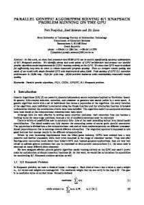
Fig. 1 - Network layer addresses used by one computer during one week IPv6 brings new methods for address assignment. Computers use more addresses per interface. A link local address is generated automatically when an interface is enabled and the address is expected to be used for communication inside a LAN. Routers advertise network prefixes by ICMPv6 router advertisements (RAs) from which an operating system usually generates an IPv6 address using modified EUI-64 [10]. Additionally, privacy extension [11] may be used. In this case, operating system periodically generates a new address that is used to establish communication with computers outside the LAN. RA may indicate that DHCPv6 should be used to
obtain another address. Fig. 1 - Network layer addresses used by one computer during one weekshows a list of IPv6 addresses that are used during one week by one computer. Moreover, the computer communicates by more than one IP address at the same time. An LI system should be aware of these techniques and be able to identify a user even if privacy extension is used. There are several methods to achieve this goal. However it depends on the ISP network architecture and if the ISP uses stateless (RA) or stateful (DHCPv6) address configuration. User identity can be achieved by monitoring traffic or collecting information from router's neighbour cache or systems logs. These two options are elaborated in the following: 1.
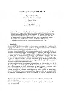
Traffic monitoring: LI probe has to be suitably located in the network. It has to be placed in the L2 network together with the device we want to intercept. It also has to have access to all traffic coming through edge L3 switch or router. This can be achieved by configuration of mirror port on the router or by using TAP device (passive device able to split network traffic). The probe is than capable to learn IPv6-MAC binding. A MAC address is usually the sufficient identifier, because it has to be unique on a LAN segment. A device using the privacy extension can configure several different IPv6 addresses on an interface, but all these addresses will have the same MAC address (see Fig. 2Error! Reference source not found.). Advantage of this solution is configuration independence – it does not matter if stateless or stateful configuration is used. The probe needs to be able to parse relevant packets (RA or DHCPv6). This mechanism also allows LI system to send required messages (e.g. user logged in) immediately. Disadvantage is high performance requirements on the probe – it has to be able to handle whole traffic coming through the router.
Fig. 2 - Interface of a computer with 1) MAC address, 2) IPv4 address, 3) active privacy extension IPv6 address, 4) deprecated privacy extension 2.
Collecting necessary information from more sources (DHCPv6 log, Routers neighbour cache): e.g. via syslog or polling devices directly, can be another solution to identify a user in an IPv6 network. LI probe needs to poll data from routers neighbour cache, if stateless configuration is used, or from DHCPv6 server – for a stateful address assignment. Neighbour cache consists of IPv6 – MAC binding. As described above, this should be sufficient information, if the probe is located in the same LAN segment. A DHCP Unique Identifier (DUID) can be learned from DHCPv6 logs. The DUID identifier can be e.g. MAC address, concatenation of time and MAC address or something completely different. Most common identifier used today is a concatenation of time and MAC address. The probe can learn MAC address from this DUID. This is not recommended by RFC 3315, because clients and servers must not interpret DUIDs. However, this solution is working and some network administrators have already deployed similar system because it overcomes some other limitations of DUID. An advantage of collecting necessary information is the simplicity of the probe. A disadvantage is that necessary messages are not send immediately but with a polling interval delay.
3.2
Interception by Internet Service Providers
Small office/home office (SOHO) LANs are regularly shared by more than one user. These networks are connected to an internet service provider's (ISP's) network through ADSL, cable link etc. by a device operating on network layer (e.g. router). An LI inside a SOHO network could reveal an investigation in progress. Consequently, data from SOHO networks are intercepted by ISPs. IPv4 SOHO networks have usually only one global IPv4 address assigned. Network address translation (NAT) enables communication between SOHO LAN and Internet. An ISP sees that all traffic of a SOHO network originates from a single IPv4 address. Thus, an ISP is not technically able to distinguish computers inside a SOHO LAN. NAT translation is not required for IPv6 networks thanks to the size of the IPv6 address space. If a LI system was able to distinguish suspect's IPv6 addresses from IPv6 addresses of other users inside the same SOHO LAN, interception of benign traffic could be avoided. Unfortunately, a network provider is not able to determine if an IPv6 address belongs to the suspect or not. In contrast, LEA possesses extended knowledge of interception targets and during examination of intercepted data can determine whether an IPv6 address belongs to a suspect or not. In latter case LEA can order network access provider not to intercept traffic of specific IPv6 address and consequently increase privacy of other users sharing a SOHO LAN with a suspect.
3.3
Multicast
Multicast provides a possibility to send messages to a group of computers while minimising required network bandwidth. Multicast was rarely used inside IPv4 networks. As a result, interception of multicast traffic is not covered by ETSI documents. On the contrary, multicast is one of key features of IPv6 networks. A suspect might exploit multicast groups for communication with other companions. Therefore, multicast traffic produced or consumed by a suspect should be intercepted. Network hosts employ Multicast Listener Discovery (MLD) [17], [18] to subscribe to a multicast group. Devices operating on network layer process MLD messages. If network layer device already listens to the requested multicast group, it does not send any MLD message outside the original LAN. The LI has to be performed between an interception target and the first device operating on the network layer to provide sufficient information about membership of a suspect in multicast groups. When a LI is located outside the LAN of an interception target, it is not technically possible to determine whether a suspect or another host in the network is trying to join a multicast group.
3.4
Transition Mechanisms
Transition mechanisms were proposed to allow connection of an IPv4 host to an IPv6 network, if a native IPv6 connectivity is not deployed. Several transition techniques are available. Most used techniques are 6to4 (see RFC 2473 [20] and RFC 3056 [21]), Teredo (in RFC 4380 [22]) and ISATAP (in RFC 5214 [23]). These mechanisms use encapsulation of an IPv6 datagram in an IPv4 datagram (Protocol field in an IPv4 header is set to 41) or in a UDP datagram. Windows OS have these techniques enabled by default and if a native IPv6 connectivity is not available, they try to obtain IPv6 connectivity using these tunnelling mechanisms. 6to4 mechanism is used if a device has public IPv4 address. It uses direct encapsulation of an IPv6 datagram inside an IPv4 datagram. Teredo allows obtaining IPv6 connectivity even behind NAT so it is usually used in SOHO networks. Teredo encapsulates IPv6 datagrams in IPv4-UDP packets. ISATAP is mechanism which let IPv6 islands inside an IPv4 network connect to IPv6 Internet. It uses the same encapsulation technique as 6to4: an IPv6 datagram inside an IPv4 datagram with Protocol field set to 41. LI systems should be aware of these techniques. A LI probe needs to decapsulate traffic, and intercept a target even inside a tunnel. This is not trivial e.g. for Teredo mechanism where every UDP packet payload needs to be examined if it contains an IPv6 header.
4 Proposed architecture The architecture of lawful interception system defined by ETSI technical specifications comprises several blocks performing specific functions (see Fig. 3). In the following text we describe the proposed implementation of these blocks.
Fig. 3 - Function blocks defined by ETSI TR 102 528 [19]
4.1
Administration Function
The purpose of the administration function (AF) is to handle requests from a LEA for interceptions to be performed on the side of the intercepting entity. An interception target is identified by a unique identifier; however, its form varies according to the type of communication network at the particular network provider or service provider (e.g. Network Access Identifier used in mobile networks to authenticate users, cable modem identifier, or IP address). The internal structure of the AF is described in Fig. 4.
Fig. 4 - Administration Function architecture The controller (1) accepts interception requests from LEAs via handover interface (HI1) defined by ETSI using a well-defined format. These requests include an identification of a target inside a monitored network (e.g. name of the user, its telephone number etc.). This communication must proceed in a secure way (e.g. using VPN connection). The trusted employee will then analyse the request. This transformation includes setting a network identifier, duration of interception process, and a type of the interception (i.e. signalling data or both signalling data and content of the communication). Signalling data are called Intercept Related Information (IRI). Note that network identifier specified in this step is not necessarily an IP address, since such information is definitely not known prior to the connection establishment of the users connecting dynamically (e.g. ADSL connections). In most cases, it would not be an IP address in IPv6 networks. Internal configuration requests are then inserted to the priority queue of waiting interceptions (2) where requests are handled according to the scheduler (3). Interception Scheduler (3) handles both priority queues with active and waiting interceptions. Moreover, it configures the Content of Communication Trigger Function (CCTF) and Intercept Related Information Internal Interception Function (IRI-IIF) blocks. System State Reporting (4) informs the LEA about ongoing and scheduled interceptions and possible failures in the system during interception process.
4.2
Intercept Related Information Internal Interception Function
IRI-IIF block creates IRI information that includes: user attempts to connect to the network (both successful and not), changes in the connection status, service specific details and timestamp information. The detail on architecture is in Fig. 5.
Fig. 5 - IRI-IIF architecture IRI-IIF block receives data from two sources and transform them into IRI. First source is a pre-processed data such as logs and other outputs of applications used for network monitoring. The second input is raw network traffic. There are two data storages for system configuration. The L2-L3 Address Mapping storage (1) saves mapping of network layer (logical) addresses to one link layer (physical) address. The mapping is created independently of active interceptions. The system needs to examine data provided from neighbour cache, ARP cache or another similar mechanism. The mapping is effective if the interception is located in the suspect's network. Interception L2-L4 Configuration storage (2) keeps identifiers of active interceptions (e.g. MAC addresses, IP addresses and ports). The analyser (3) gathers suitable application logs and selects entries that define a required interception or a new IRI. IRIs are sent to Mediation Function directly. Analyser also processes entries in a neighbour cache and an ARP cache and creates mapping of logical addresses to physical addresses and stores it in L2-L3 Address Mapping (1). The Tunnel detector (4) inspects a copy of defragmented network traffic. The Network Identifier Detection (5) detects events that trigger an interception. Then a new configuration with new rules for interceptions is passed to the Interception L2-L4 Configuration (2). Traffic that is not a subject of any interception is dropped. The IRI detector reconstructs flows and constructs IRI (6).
4.3
Mediation Function
The main purpose of the Mediation Function (MF, see Fig. 3Error! Reference source not found.) is to process IRI and Content of Communication (CC) that are formatted according to the delivery specification of the Law Enforcement Monitoring Facility (LEMF). Note that all incoming and outgoing data have to be encrypted in order to prevent the unauthorized eavesdropping and analysis of intercepted packets. The structure of the Mediation Function is depicted in Fig. 6. At the input, there are buffers for temporary storage of incoming interception data (IRI and CC) that involves functions performing data pre-processing. The IRI buffer (1) correlates records intercepted by different network devices. CC buffer (2) searches for known attempts to deceive the system [15]. If such attempt is detected a new IRI is constructed to inform LEMF. Handover Managers and Delivery Functions provide intercepted data to LEMF. There is one Handover Manager for IRI (3) and one for CC (4), one Delivery Function for each LEMF and each type of intercepted data present in the
Mediation Function. Handover Manager is intended to manage HI2 and HI3 interfaces for communication with LEMF. It aggregates and completes payload, inserts required header, adds padding if necessary, selects and communicates with particular Delivery Function. The Delivery Function maintains connection with LEMF (keep-alive mechanisms), encodes and decodes messages to and from LEMF, encrypts the data provided by the Handover Manager using security credentials obtained from LEA, checks integrity of data and buffers them at the output interface. Connection with LEMF is provided using TCP protocol in order to prevent a data loss. System Alive Detection (5) reports failures to LEA.
Fig. 6 - Mediation Function Mediation function also monitors the state of other function blocks and their interfaces (5). Whenever a failure appears, details are passed to the AF where affected interceptions are identified. The AF subsequently notifies LEAs.
4.4
Content of Communication Trigger Function, Content of Communication Internal Interception Function
Content of Communication Trigger Function (CCTF) is intended to manage Content of Communication Internal Interception Function (CC-IIF) deployed in the particular network devices (e.g. probes, routers). CCTF has to be aware of the network topology and placement of CC-IIF devices. CCTF creates configuration and remotely communicates with CC-IIF devices. Basically, the CC-IIF is a filtering probe that captures traffic intended for predefined interception targets based on a filter configuration. The traffic is being captured in both directions. Moreover, the probes must be implemented in such a way, that the intercepted users must not be aware of any monitoring. The CC-IIF encrypts and sends all captured traffic to the Mediation Function for further processing. There is a heart-beat mechanism implemented in the CC-IIF to keep overview of state of running probes and interceptions in progress. Should a CC-IIF probe crash, any previous configuration would be erased and, during a normal reboot, a configuration checkout would be performed through CCTF. The CC-IIF has to implement audit mechanisms of the probe access in order to keep track of all configuration requests and any unauthorized access attempts. Naturally, all configuration communication is encrypted as well. The content of communication may be used for investigation purposes; therefore, no packet should be lost during capturing and transferring to the MF, and a reliable protocol, e.g. TCP, should be used.
5 Expected Deployment In the first part of the paper, we described challenges of LI in IPv6 networks and presented architecture overview of proposed LI system.This section concerns implementation of a proposed architecture in a real network and discusses several implementation related considerations and issues.
5.1
Network probes
During LI system implementation, mapping of functional blocks (depicted on Fig. 3) to HW devices is an important task. AF and MF (together with CCTF on the same device) are usually implemented by proprietary SW solutions compatible with LI standards. LI itself can’t work without help of specialised probes appropriately deployed in Internet Service-Provider (ISP) network. These probes have built-in IRI-IIF and/or CC-IIF blocks. We can categorize probes by type of intercepted traffic they should deliver: •
CC probes – Main goal is to intercept all content of communication from suspect. They should be able to quickly filter high data throughput (in Gbps). CC probes should also be able to buffer traffic for a short period hence none would be lost during reconfiguration of interception.
•
IRI probes – Their main goal is to intercept signalization traffic most preferably the one containing suspect identity information. IRI probes should be able to generate and pass current intercept stream meta-information to MF and CC-IIF. Although, IRI probes do not need to cope with high data throughput, their control logic has to be more sophisticated (comparing to CC probes) in order to process application layer data.
•
CC/IRI probes – CC/IRI probes combine above described functionality of CC probes and IRI probes.
5.2
Deployment Strategies
CC probes should be located as close to suspect as possible. Best option is between target computer and aggregation switch hence we could intercept all CC traffic and we could be sure that none would pass through unnoticed. However this solution is barely scalable – just imagine that for every suspect we need one CC probe. IRI probes work best if situated as close to end-point of signalization traffic as possible. This end-point could be service-providing device (e.g. DHCP or Radius server, call managers and telephone private branch exchange (PBX), email server, etc.) – more generally any active device processing or working with suspect possible network identity (see section 3). Problem with precise deployment of IRI probes depends on location of endpoints. Those end-points could be placed inside or outside of ISP network:
5.3
•
Inside ISP network – Usually there’s no obstacle placing IRI probes near them. Some already existing proprietary solutions [24] even integrate IRI-IIF block into such devices (e.g. as a part of Radius server).
•
Outside ISP network – In this case, the challenge is to select a place in an ISP network where tracked traffic indeed flows. Good choices are either on links to border routers (where possible traffic of interest is exiting ISP network) or on links to routers in distribution layer (sufficiently close to suspect). However, it strongly depends on specific situation and mostly on type of service to be intercepted.
Example Scenario
Multiple scenarios are possible based on real networks; Fig. 7 shows one of them. CC probes are on links to aggregation switches. This approach is scalable for multiple suspects eavesdropping of CC flows. The CC probes can also intercept multicast traffic because of close proximity to a distribution router (which serves as IGMP/MLD designation router). Inevitable disadvantage is that the CC probe is unaware of communication between two suspects on same LAN segment. One IRI probe is on link to DHCP server, other one is on exit link to border router.
Fig. 7 - Example scenario of deployment
6 Conclusion There are several standards for LI available that define requirements on intercepted data and architecture of LI system as a whole. Advent of IPv6 protocol unveils several shortcomings of current LI specifications. One of the major concerns is user identification for IPv6 no longer use traditional IPv4 address assignment methods. Current identification methods employing RADIUS and DHCP are not sufficient for IPv6. Additionally, other forms of communication than one-to-one would become pervasive in IPv6 networks. Multicast allows establishment of groups of network nodes identified by special IPv6 addresses. SOHO networks often share one global IPv4 address and thus separation of a specific SOHO network user is technically impossible. In contrast, due to large number of available IPv6 addresses, any two computers do not share same IPv6 address. In cooperation with LEA recognition of specific users using distinct IPv6 addresses could be established; thus, privacy of users connected to SOHO networks could be increased. Other issues arise with using tunnelling mechanisms. In our work we describe design of LI system. We propose techniques coping with aforementioned issues that directly affect the LI system architecture. We integrate our architecture into function blocks described by ETSI [19]. We partition those blocks into separate devices. We discussed considerations and issues connected with deployment. The entire system is under development and future work will include experience with the system implementation and its operation.
7 Acknowledgement This work is part of the project VG20102015022 supported by Ministry of the Interior of the Czech Republic and was partially supported by the research plan MSM0021630528. We would like to thank Miroslav Švéda and Ondřej Ryšavý for their help during the preparation of the paper.
8 Bibliography [1] ETSI. Lawful Interception (LI); Handover Interface and Service-Specific Details (SSD) for IP delivery; Part 1: Handover specification for IP delivery. 2006. ETSI TS 102 232-1 V2.1.1. [2] ETSI. Lawful Interception (LI); Handover Interface and Service-Specific Details (SSD) for IP delivery; Part 2: Service-specific details for E-mail services. 2009. ETSI TS 102 232-2 V2.4.1.
[3] ETSI. Lawful Interception (LI); Handover Interface and Service-Specific Details (SSD) for IP delivery; Part 3: Service-specific details for internet access services. 2009. ETSI TS 102 232-3 V2.2.1. [4] ETSI. Lawful Interception (LI); Handover Interface and Service-Specific Details (SSD) for IP delivery; Part 4: Service-specific details for Layer 2 services. 2010. ETSI TS 102 232-4 V2.2.1. [5] ETSI. Lawful Interception (LI); Handover Interface and Service-Specific Details (SSD) for IP delivery; Part 5: Service-specific details for IP Multimedia Services. 2007. ETSI TS 102 232-5 V2.1.1. [6] ETSI. Lawful Interception (LI); Concepts of Interception in a Generic Network Architecture. 2006. ETSI TR 101 943 V2.2.1. [7] Baker, F., Foster, B. and Sharp, C. RFC 3924 - Cisco Architecture for Lawful Intercept in IP Networks. [Online] October 2004. http://tools.ietf.org/html/rfc3924. [8] Aqsacom. Lawful Interception for IP Networks - White Paper. 2005. [9] Hinden, R. and Deering, S. RFC 4291 - IP Version 6 Addressing Architecture. [Online] February 2006. http://tools.ietf.org/html/rfc4291. [10] Narten, T., Draves, R. and Krishnan, S. RFC 4941 - Privacy Extensions for Stateless Address Autoconfiguration in IPv6. [Online] September 2007. http://tools.ietf.org/html/rfc4941. [11] Colitti, L., Di Battista, G. and Patrignani, M. Pv6-in-IPv4 Tunnel Discovery: Methods and Experimental Results. IEEE Transactions on Network and Service Management. April 2004, pp. 30-38. [12] Rojas, A., Branch, P. and Armitage, G. Predictive Lawful Interception in Mobile IPv6 Networks. ICON 2007 - 15th IEEE International Conference on Networks, 2007. November 2007, pp. 501-506. [13] Rigney, C., et al. RFC 2865 - Remote Authentication Dial In User Service (RADIUS). [Online] June 2000. http://tools.ietf.org/html/rfc2865. [14] Frankel, S., et al. Guidelines for the Secure Deployment of IPv6. National Institute of Standards and Technology, 2010. p. 188. NIST Special Publication 800-119. [15] Cronin, E., Sherr, M. and Blaze, M. On the (un)reliability of eavesdropping. Int. J. Secur. Network. February 2008, Sv. III, 2, pp. 103-113. [16] Karpagavinayagam, B., State, R. and Festor, O. Monitoring Architecture for Lawful Interception in VoIP Networks. 2007. [17] Deering, S. and Fenner, W. RFC 2710 - Multicast Listener Discovery (MLD) for IPv6. [Online] October 1999. http://tools.ietf.org/html/rfc2710. [18] Vida, R. and Costa, L. RFC 3810 - Multicast Listener Discovery Version 2 (MLDv2) for IPv6. [Online] June 2004. http://tools.ietf.org/html/rfc3810. [19] ETSI. Lawful Interception (LI); Interception domain Architecture for IP networks. 2006. ETSI TR 102 528 V1.1.1. [20] Conta, A. and Deering, S. Generic Packet Tunneling in IPv6 Specification. [Online] December 1998. http://tools.ietf.org/html/rfc2473. [21] Carpenter, B. and Moore, K. Connection of IPv6 Domains via IPv4 Clouds. [Online] February 2001. http://tools.ietf.org/html/rfc3056. [22] Huitema, C. Teredo: Tunneling IPv6 over UDP through Network Address Translations (NATs). [Online] February 2006. http://tools.ietf.org/html/rfc4380. [23] Templin, F., Gleeson, T. and Thaler, D. Intra-Site Automatic Tunnel Addressing Protocol (ISATAP). [Online] March 2008. http://tools.ietf.org/html/rfc5214. [24] Cisco. RADIUS-Based Lawful Intercept . [Online] March 2006. http://www.cisco.com/en/US/docs/ios/12_2sb/feature/guide/sb_radlw.html.


![WhatsApp network forensics - VUT FIT [PDF]](https://m.moam.info/img/260x300/whatsapp-network-forensics-vut-fit-pdf_649a0b25098a9e7e658b461b.jpg)

